Elkron IR200 Handbuch
Inhaltsverzeichnis
Verfügbare Sprachen
Verfügbare Sprachen
Quicklinks
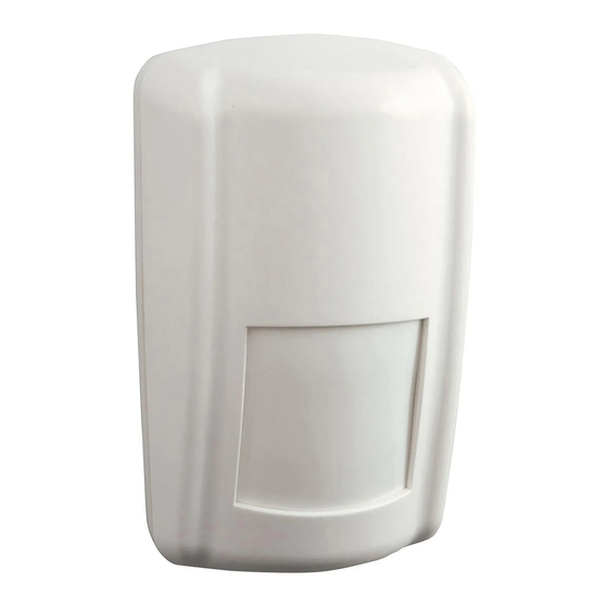
PIR MOTION DETECTOR (IR200)
DS80IR9B-001A
DETECTEUR DE MOUVEMENT PIR (IR200)
LBT80624
PIR BEWEGUNGSSENSOR (IR200)
GB
The PIR picks up movements within an assigned area and signals the Control Panel to activate the
alarm if an intruder crosses its' path of detection.
The PIR consists of a two-part design made up of a cover and a base. The cover contains all the
electronics and optics and the base provides a means of fixing. The base has knockouts to allow
mounting on either a flat surface or in a corner situation with fixing screws and plugs provided.
Provision for a tamper switch that will be activated when the cover is detached from the base prevents
unauthorized access and removal from the mounting surface. The PIR can also alert you to signal
communication problems and low battery situations.
The PIR is designed to give a typical detection range of 12 meters when mounted at 2 meters above
ground.
IDENTIFYING THE PARTS
Remove the cover by loosening the button fixing screw, the inside of the PIR will revealed as shown.
Learn/Test Button
This button is used for testing the radio performance and for
learning purpose.
Tamper Switch
The Tamper switch protects the enclosure from being opened.
Test/Normal Mode Jumper Switch (JP1)
It is a 3-pin jumper switch
If the jumper link is in inserted between the left 2 pins, the
PIR is in Test mode.
If the jumper link is inserted between the right 2 pins, the PIR is in Normal operation mode.
1/12
Inhaltsverzeichnis

Verwandte Anleitungen für Elkron IR200


Inhaltszusammenfassung für Elkron IR200
-
Seite 7: Kennzeichnung Der Teile
Das PIR erfasst Bewegungen innerhalb eines zugeordneten Sektors und meldet diese an die Zentrale, die den Alarm aktiviert, wenn ein Eindringling die Erfassungsgrenze des Sektors überschreitet. Das PIR besteht aus einer zweiteiligen Konstruktion, aus einem Deckel und einer Basis. Der Deckel beinhaltet die gesamte Elektronik, sowie die Optik und die Basis die Befestigungsmöglichkeiten. -
Seite 8: Led-Anzeige
TEST MODUS Der PIR kann in den Test-Modus geschaltet werden, indem man das Brückenglied zwischen die 2 linken Polen des Test Modus Brückenschalters steckt. Im Test-Modus schaltet die Schlummerfunktion aus und schaltet die LED Anzeige an, damit es jedes Mal, wenn eine Bewegung registriert wird, aufblinkt. Hinweis: Die Steckbrücke sollte nicht in dieser Position bleiben, sonst verkürzt sich die Lebensdauer der Batterie und die Batterieanzeige (Batterie niedrig) am PIR könnte nicht wahrgenommen werden. -
Seite 9: Installationsempfehlungen
MONTAGEMETHODE • Der PIR kann entweder auf einer glatten Oberfläche oder in einer Ecke mit Befestigungsschrauben montiert werden. Wandmontage • 2x Ausbrüche Die Basis hat Ausbrüche, wo das Plastik zu Anbauzwecken dünner ist. Zwei Ausbrüche sind für die Montage auf einer ebenen Fläche und vier Ausbrüche für die Montage in einer Ecke (siehe Abbildung). - Seite 10 10/12...
- Seite 11 11/12...