Werbung
Quicklinks
GAMMA instabus
Tür/Fensterkontakt
S 290 w,
door/window contact
S 290 w
Tür/Fensterkontakt
S 290 br
door/window contact
S 290 br
Bedien- und Montageanleitung
Operating and Mounting Instructions
Stand: Juni 2009
Issued: June 2009
A5E02470538A
DS01
Produkt- und Funktionsbeschreibung
Der Magnetschalter wird als Öffnungsmelder zur Überwachung
von Fenstern und Türen angeboten. Er wird durch einen separa-
ten Permanentmagneten berührungslos betätigt. Vergrößert
sich der Abstand zwischen Magnetschalter und Magnet, öffnet
der Reedkontakt.
Er erfasst den Zustand (geöffnet oder geschlossen). Über binäre
5WG1 290-7AB11
Meldeeingänge kann diese Information an ein KNX-System
übertragen werden. Die Auswertung dieser Zustände dient z.B.
zu einer energieoptimierten Heizung- und Klimasteuerung aber
auch für Sicherheitsfunktionen, zur Überwachung der Gebäu-
deaussenhaut in Gefahrenmeldeanlagen.
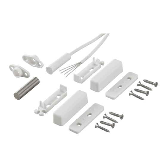
Der Magnetschalter wird in einem Set angeboten, bestehend
aus:
5WG1 290-7AB81
• 1 Magnet, Ø 8 x 30 mm
• 1 Magnetkontakt Ø 8 x 30 mm in einem vollvergossenen
Kunststoffgehäuse, mit 5 m Anschlußkabel LiYY 4 x 0,14
mm²
• 2 x Aufbaugehäuseoberteile (43 x 12 x 12) mm
• 2 x Aufbaugehäuseunterteile
• 4 x Distanzplatten mit 2 x 4 mm bzw. 2 x 2 mm Stärke
• 2 x Einbauflansche
• 4 x antimagnetische Senkblechschrauben
DIN 7982-ST2, 9 x 16-A2
Das Set ist in den Farben weiß und braun lieferbar.
Tür/Fensterkontakt S 290 in weiß
Tür/Fensterkontakt S 290 in braun
Der Magnetschalter ist in ein Gehäuse eingegossen und damit
gegen Staub und Feuchtigkeit geschützt.
Er wird in Fenster- und Türrahmen, die aus nichtmagnetischen
Materialien bestehen, eingelassen (Einbaumontage) bzw. auf
diesen montiert (Aufbaumontage). Entsprechend werden der
Magnetkontakt und der Magnet parallel oder stirnseitig zuein-
ander in Fensterrahmen / Türblatt bzw. Fensterstock / Türstock
montiert.
Der Aufbau auf ferromagnetische Materialien ist nur unter Ver-
wendung der Aufbaugehäuse incl. Distanzplatten zulässig.
Die Aufbaugehäuse dürfen nur mit antimagnetischen Schrau-
ben befestigt werden.
Weitere Informationen
http://www.siemens.de/gamma
Technische Daten
• Kontaktart:
• Schaltspannung:
• Schaltstrom:
• Kontaktbelastbarkeit:
• Übergangswiderstand:
mΩ
• zul. Betriebsspannung:
• Schaltspiele:
• Anschlusskabel:
• Innenleiter:
• Magnet:
• Montageabstand:
• Schutzart nach IEC:
• Umweltklasse gem. VdS:
• Luftfeuchtigkeit nach DIN:
• Lagertemperatur:
• Betriebstemperatur:
• Gehäusematerial:
• Gehäusefarbe:
• Gewicht Set:
• Abmessungen
Aufbaugehäuseoberteil (L X B X T): 43 x 12 x 12 mm
Magnetkontakt (Ø x L):
Magnet (Ø x L):
• CE:
• VdS-Nr.:
• VdS-Klasse:
Montage und Verdrahtung
Installationshinweise
Die Montage und der Einsatz der Magnetschalter erfolgt gemäß
VdS-Richtlinie 2311.
Der Einbau bzw. Aufbau der Magnetschalter und der dazugehö-
rigen Magnete ist in zwei Varianten möglich:
-
-
Einbaumontage:
Mit der Einbauversion besteht die Möglichkeit den Magnet und
den Magnetschalter in Fenstern und Türen einzulassen um die-
se vor Zugriff zu schützen und optisch zu verbergen.
Bei der Fenstermontage wird der Magnet im Fensterflügel und
der Magnetschalter im Rahmen angebracht. Bei der Türmonta-
ge wird der Magnet in der Tür und der Magnetschalter im Tür-
rahmen montiert. Die Montage muss axial in Längsfluchtlinie
erfolgen (siehe Bild 1).
D
5WG1 290-7AB11
5WG1 290-7AB81
1-poliger Schließer
max. 110 V DC
10 µA... 100 mA
max. 5 W
max. 110 V DC
≥10
7
LiYY 4 x 0,14 mm²,
Länge: 5 m
gleichfarbig,
Cu-Litze abisoliert u.
verzinnt
AINiCo 500
axial ≤ 15 mm
parallel ≤ 15 mm
IP 68
IV
+ 40° C, 93 % rel. LF
- 25° C ... + 70° C
- 25° C ... + 70° C
ABS
weiß (RAL 9003)
braun (RAL 8016)
122 g
8 x 30 mm
8 x 30 mm
konform
G 191568
B
axial (bei Einbaumontage)
parallel (bei Aufbaumontage)
Seite 1 von 4
Product- and Applications Description
The proximity switch is provided as an opening alarm for moni-
toring windows and doors. It is operated in a contactless man-
ner by a separate permanent magnet. If the clearance between
the proximity switch and the magnet increases, the reed con-
tact opens.
It records the status (open or closed). This information is trans-
ferred to a KNX system via binary reporting inputs. The analysis
of these states is used, for example, for an energy-optimised
heating and climate control system, as well as for safety func-
tions to monitor the building shell in risk reporting systems.
The proximity switch is provided in a set, consisting of:
• 1 magnet, Ø 8 × 30 mm
• 1 magnetic contact, Ø 8 × 30 mm in an encapsulated plastic
housing, with a 5 m lead cable LiYY 4 × 0.14 mm²
• 2 × housing tops (43 × 12 × 12) mm
• 2 × housing bottoms
• 4 × distance plates 2 × 4 mm or 2 × 2 mm thickness
• 2 x building-in flanges
• 4 × anti-magnetic recess plate screws
DIN 7982-ST2, 9 × 16-A2
The set is available in white or brown.
door/window contact set 290, white
door/window contact set 290, brown
The proximity switch is cast into a housing and in this way is
protected against dust and moisture.
It is inset into (built-in) or mounted on (built-on) window and
door frames made from non-magnetic materials. Accordingly,
the magnet contact and magnet are mounted in parallel or fac-
ing each other in the window frame / door leaf or window sill /
door frame.
Mounting on ferromagnetic materials is only permitted with the
use of the housing incl. distance plates.
The housing should only be fixed with anti-magnetic screws.
Additional Information
http://www.siemens.com/gamma
Technical Specification
• Type of contact:
• Switching voltage:
• Switching current:
• Contact loading:
max. 150
• Transfer resistance:
• Permitted operating voltage:
• Switching cycles:
• Lead cable:
• Inner conductor:
• Magnet:
• Mounting clearance:
• Type of protection to IEC:
• Environmental class to VdS:
• Humidity to DIN:
• Storage temperature:
• Operating temperature:
• Housing material:
• Housing colour:
• Set weight:
• Dimensions
Housing top (L × W × D):
Magnet contact (Ø × L):
Magnet (Ø × L):
• CE:
• VdS no.:
• VdS class:
Mounting and wiring
Installation notes
The proximity switch is mounted and used in accordance with
VdS Directive 2311.
There are two installation options for built-in or built-on mount-
ing of the proximity switch and the associated magnets:
-
axial (for built-in mounting)
-
parallel (for built-on mounting)
Built-in mounting:
With the built-in version, there is the option to build the magnet
and proximity switch into doors and windows, in order to pro-
tect them from access and hide them from view.
With window mounting, the magnet is fitted in the window leaf
and the proximity switch in the frame. With door mounting, the
magnet is mounted in the door and the proximity switch in the
door frame. The mounting must be on the building line axially
(see figure 1)
Page 1 of 4
GB
5WG1 290-7AB11
5WG1 290-7AB81
1-pole normally open
contact
max. 110 V DC
10 µA...100 mA
max. 5 W
max. 150 mΏ
max. 110 V DC
≥10
7
LiYY 4 × 0.14 mm²,
Length: 5 m
same colour,
Copper-strand, stripped
and tinned
AINiCo 500
axial ≤ 15 mm
parallel ≤ 15 mm
IP 68
IV
+ 40°C,
3 % rel. humidity
- 25°C ... + 70°C
- 25°C ... + 70°C
ABS
white (RAL 9003)
brown (RAL 8016)
122 g
43 × 12 × 12 mm
8 × 30 mm
8 × 30 mm
compliant
G 191568
B
Werbung

Verwandte Anleitungen für Siemens S 290 w


Inhaltszusammenfassung für Siemens S 290 w
- Seite 1 Permanentmagneten berührungslos betätigt. Vergrößert ner by a separate permanent magnet. If the clearance between sich der Abstand zwischen Magnetschalter und Magnet, öffnet the proximity switch and the magnet increases, the reed con- S 290 w, der Reedkontakt. tact opens. door/window contact Er erfasst den Zustand (geöffnet oder geschlossen).
- Seite 2 Bei antimagnetischen Materialien können die Einbauflansche With anti-magnetic materials, the building-in flange is used (see verwendet werden (siehe Bild 2). Magnet und Magnetschalter- figure 2). Magnet and proximity switch housing must be fixed gehäuse müssen mittels Klebstoff (Cyanacrylat – Sekundenkle- in the building-in flange with adhesive (cyanacrylate –...
- Seite 3 Magnetschalter proximity switch 15mm 15mm magnet Magnet Ø 8mm x 30mm Ø 8mm x 30mm offset in an axial direction <3mm Versatz in axialer Richtung <3mm Bild 4: parallele Montage Figure 4: parallel mounting Achtung Attention Der Magnetschalter und der Magnet müssen im Aufbaugehäu- The proximity switch and magnet must be installed respectively seunterteil jeweils so eingelegt werden, dass sie parallel ohne so that they are parallel without a lateral offset!
- Seite 4 • Ein defektes Gerät ist mit einem Rücklieferschein der zustän- • A faulty device shall be sent with a Return Good Note for Ser- digen Vertriebsniederlassung an folgende Adresse zusen- vice provided by the appropriate Siemens sales office to the den: following address:...