Herunterladen Inhalt Inhalt Diese Seite drucken
AFRISO FloCo-Top-1K Betriebsanleitung

AFRISO FloCo-Top-1K Betriebsanleitung

Automatischer heizölentlüfter mit integriertem filter
Vorschau ausblenden Andere Handbücher für FloCo-Top-1K:

Werbung

Verfügbare Sprachen
  • DE

Verfügbare Sprachen

  • DEUTSCH, seite 1
Betriebsanleitung
Automatischer Heizölentlüfter
mit integriertem Filter
Version: 06.2020.0
ID: 900.000.0287
Copyright 2020 AFRISO-EURO-INDEX GmbH. Alle Rechte vorbehalten.
in Verbindung mit einem
PA-Schlauch 4 x 1 mm
MVV TB
C 2.15.23
EN 12514-2
FloCo-Top-1K
DE

Werbung

Inhaltsverzeichnis
loading

Inhaltszusammenfassung für AFRISO FloCo-Top-1K

  • Seite 1 Betriebsanleitung Automatischer Heizölentlüfter mit integriertem Filter FloCo-Top-1K Copyright 2020 AFRISO-EURO-INDEX GmbH. Alle Rechte vorbehalten. MVV TB C 2.15.23 EN 12514-2 in Verbindung mit einem PA-Schlauch 4 x 1 mm Version: 06.2020.0 ID: 900.000.0287...
  • Seite 2 Über diese Betriebsanleitung Über diese Betriebsanleitung Diese Betriebsanleitung beschreibt den automatischen Heizölentlüfter mit integriertem Filter „FloCo-Top-1K“ (im Folgenden auch „Produkt“). Diese Betriebsanleitung ist Teil des Produkts. • Sie dürfen das Produkt erst benutzen, wenn Sie die Betriebsanleitung vollständig gelesen und verstanden haben.
  • Seite 3: Informationen Zur Sicherheit

    Warnhinweise sind in dieser Betriebsanleitung mit Warnsymbolen und Sig- nalwörtern gekennzeichnet. Abhängig von der Schwere einer Gefährdungs- situation werden Warnhinweise in unterschiedliche Gefahrenklassen unter- teilt. HINWEIS HINWEIS macht auf eine möglicherweise gefährliche Situation aufmerksam, die bei Nichtbeachtung Sachschäden zur Folge haben kann. FloCo-Top-1K...
  • Seite 4 Führen Sie bei der Verwendung des Produkts alle Arbeiten ausschließlich unter den in der Betriebsanleitung und auf dem Typenschild spezifizierten Bedingungen und innerhalb der spezifizierten technischen Daten und in Übereinstimmung mit allen am Einsatzort geltenden Bestimmungen, Nor- men und Sicherheitsvorschriften durch. FloCo-Top-1K...
  • Seite 5 Gefährdungen auftreten können, die nicht direkt vom Produkt ausge- hen. Veränderungen am Produkt Führen Sie ausschließlich solche Arbeiten an und mit dem Produkt durch, die in dieser Betriebsanleitung beschrieben sind. Nehmen Sie keine Verände- rungen vor, die in dieser Betriebsanleitung nicht beschrieben sind. FloCo-Top-1K...
  • Seite 6: Transport Und Lagerung

    • Benutzen Sie für den Transport die Originalverpackung. • Lagern Sie das Produkt nur in trockener, sauberer Umgebung. • Stellen Sie sicher, dass das Produkt bei Transport und Lagerung stoßge- schützt ist. Nichtbeachtung dieser Anweisungen kann zu Sachschäden führen. FloCo-Top-1K...
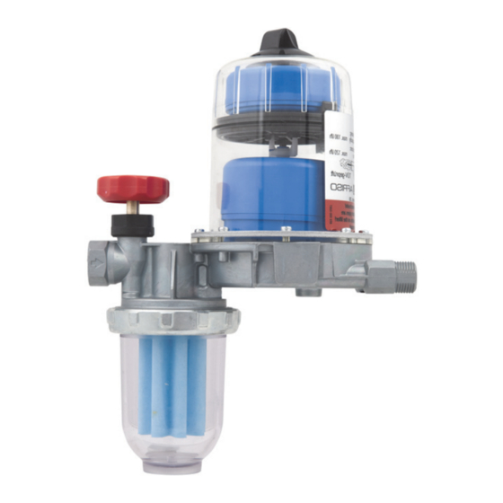
  • Seite 7: Produktbeschreibung Übersicht

    G. Wandhalter H. Anschluss Rücklauf  C. Untere Schwimmerkammer (Betriebsschwimmer) (vom Brenner) D. Obere Schwimmerkammer I. Anschluss Vorlauf (zum Brenner) (Sicherheitsschwimmer) Die obere Schwimmerkammer (D) E. Filtertasse verhindert, dass Schaum durch die Entlüftungsbohrung austreten kann. Abbildung 1: Übersicht FloCo-Top 1K FloCo-Top-1K...
  • Seite 8 Tank nachgesaugt und dem entlüfteten Brennstoff beige- mischt. A. Q Tank Düse B. Q Rücklauf C. Q Vorlauf D. Q Düse Zulassungsdokumente, Bescheinigungen, Erklärungen Das Produkt ist vom TÜV geprüft (Bericht Nummer S 133 2013 E2). FloCo-Top-1K...
  • Seite 9 Flüssigkeitssäule von circa 8 m) Saugdruck Max. -0,5 bar Prüfdruck 6 bar Filtereinsatz 50 - 70 µm Sinterkunststoff (Artikel 69960), sonstige Artikel siehe Ver- packungsetikett Werkstoff Gehäuse Zink-Druckguss Umgebungsbedingungen Umgebungstemperatur Betrieb Max. 60 °C Mediumstemperatur Max. 60 °C FloCo-Top-1K...
  • Seite 10: Montage

    Um die maximal mögliche Saugleitungslänge zu bestimmen, darf der Saug- druck -0,4 bar nicht übersteigen. Für die eintretende Filterverschmutzung sind 0,05 bar an zusätzlichem Druckverlust berücksichtigt. 5.2.1 Maximale Saugleitungslänge bei ansteigender Leitung 1. Entfernen Sie alle Rück- schlagventile am Tank und im Bereich einer selbstsichernden Sauglei- tung. FloCo-Top-1K...
  • Seite 11 > 100 > 100 15 kg/h Ø 6 mm (18 l/h) Ø 8 mm Ø 10 mm > 100 > 100 > 100 20 kg/h Ø 6 mm (24 l/h) Ø 8 mm Ø 10 mm > 100 > 100 FloCo-Top-1K...
  • Seite 12 1. Montieren Sie ein Antiheberventil, um ein Austreten (Aushebern) von flüssigem Brennstoff bei undichter Saugleitung und höher liegendem Füllstand im Tank zu verhindern. A. Kolben-Antiheberventil „KAV“ C. H = Absicherungshöhe „MAV“ B. Membran-Antiheberventil „MAV“ D. H = Absicherungshöhe „KAV“ FloCo-Top-1K...
  • Seite 13 Verwendung von Teflonband oder Hanf ist nicht zulässig. Nichtbeachtung dieser Anweisungen kann zu Sachschäden führen. 3. Dichten Sie die Saugleitung in das Innengewinde G des Gehäuses, mit zylindrischer Rohrverschraubung G nach DIN 2353 ein. Das Anzugs- moment beträgt 40 ±10 Nm. FloCo-Top-1K...
  • Seite 14 FUNKTIONSUNFÄHIGES PRODUKT • Stellen Sie sicher, dass Sie die Brennerschläuche der Vor- und Rücklauflei- tung nicht vertauschen. Nichtbeachtung dieser Anweisungen kann zu Sachschäden führen. Druckprüfung  Stellen Sie sicher, dass das Produkt nicht in die Druckprüfung mit einbe- zogen wird. FloCo-Top-1K...
  • Seite 15 A. Siku-Einsatz 35 µm B. Siku-Einsatz 50 µm C. Siku-Einsatz 70 µm D. Filz E. Stahlsieb Durchfluss Q [l/h] 5.5.2 Im Saugbetrieb mit 50 % verschmutztem Filtereinsatz A. Siku-Einsatz 35 µm B. Siku-Einsatz 70 µm C. Filz D. Stahlsieb Durchfluss Q [l/h] FloCo-Top-1K...
  • Seite 16 1. Führen Sie den Entlüftungsschlauch entlang der Saugleitung zum Tank zurück. 2. Fixieren Sie den Entlüftungsschlauch mit Kabelbindern. 3. Bringen Sie das andere Ende des Entlüftungsschlauchs an der Entlüf- tungsleitung oder am Rücklaufanschluss der Entnahmearmatur des Tanks an, um einen eventuellen Leitungsverschluss vorzubeugen. FloCo-Top-1K...
  • Seite 17: Betrieb

    Gebiete geeignet und ist druckwasserdicht bis 10 mH (1 bar Außendruck). Nach einem Hochwasserereignis ist das Produkt mit Entlüftungsschlauch weiterhin funktionsfähig.  Stellen Sie sicher, dass sich das Ende des Entlüftungsschlauchs am Rücklaufanschluss des Tanks befindet oder oberhalb des maximal mögli- chen Wasserpegels endet. FloCo-Top-1K...
  • Seite 18: Wartung

    Reinigen Sie die Kunststoffteile mit einer wässri- gen Seifenlauge Jährlich oder bei Bedarf Tauschen Sie den Filtereinsatz Alle 5 Jahre Ersetzen Sie die Brennerschläuche Spätestens nach Ersetzen Sie das Produkt 20 Jahren Nach Hochwasser Ersetzen Sie das Produkt wenn kein Entlüftungs- schlauch angeschlossen ist FloCo-Top-1K...
  • Seite 19 Wartung Filtereinsatz tauschen 7.2.1 Filtereinsatz ausbauen FloCo-Top-1K...
  • Seite 20 Wartung 7.2.2 Filtereinsatz einbauen FloCo-Top-1K...
  • Seite 21: Störungsbeseitigung

    Legen Sie die Sauglei- schaltungen des Bren- Saugleitung durch zu tung korrekt aus (siehe ners großen Leitungsdurch- Kapitel "Saugleitungs- messer der Sauglei- länge ermitteln") tung. Beim Öffnen des Antiheberventils kann eine größere Luftblase durchschlagen, die eine Störabschaltung verur- sachen kann FloCo-Top-1K...
  • Seite 22 Entlüfters durch Brennerpumpe erzeugt Führen Sie eine Saug- keinen ausreichenden druckprüfung an der Unterdruck Pumpe durch. Die Pumpe muss mindes- tens einen Unterdruck von -0,4 bar aufbauen Sonstige Störungen Bitte wenden Sie sich an die AFRISO-Service Hotline FloCo-Top-1K...
  • Seite 23: Außerbetriebnahme Und Entsorgung

    2. Entsorgen Sie das Produkt. Rücksendung Vor einer Rücksendung Ihres Produkts müssen Sie sich mit uns in Verbin- dung setzen (service@afriso.de). Gewährleistung Informationen zur Gewährleistung finden Sie in unseren Allgemeinen Geschäftsbedingungen im Internet unter www.afriso.com oder in Ihrem Kauf- vertrag. FloCo-Top-1K...
  • Seite 24: Ersatzteile Und Zubehör

    Verwenden Sie nur Original Ersatz- und Zubehörteile des Herstellers. Nichtbeachtung dieser Anweisung kann zu Sachschäden führen. Produkt Artikelbezeichnung Art.-Nr. Abbildung Automatischer Heizölent- 69960 lüfter mit integriertem Filter „FloCo-Top-1K“ Ersatzteile und Zubehör Artikelbezeichnung Art.-Nr. Abbildung Filtertasse kurz (Standard) 20254 Filtertasse kurz 20257 (mit Entleereinrichtung) O-Ring für Filtertasse...
  • Seite 25 DIN 2353 mit Kupfer-Flach- dichtung: Rohr Ø 6 mm 20509 Rohr Ø 8 mm 20508 Rohr Ø 10 mm 20510 Rohr Ø 12 mm 20512 Kolben-Antiheberventil 20240 „KAV“ Membran-Antiheberventil 20139 „MAV“ Entlüftungsschlauch, 20696 PVC, Ø 4 x 1 mm, 20 m Rolle FloCo-Top-1K...
  • Seite 26 Operating instructions Automatic fuel oil de-aerator with integrated filter FloCo-Top-1K Copyright 2020 AFRISO-EURO-INDEX GmbH. All rights reserved. MVV TB C 2.15.23 EN 12514-2 in conjunction with a PA hose 4 x 1 mm Version: 06.2020.0 ID: 900.000.0287...
  • Seite 27 About these operating instructions About these operating instructions These operating instructions describe the automatic fuel oil de-aerator with integrated filter "FloCo-Top-1K" (also referred to as "product" in these oper- ating instructions). These operating instructions are part of the product. •...
  • Seite 28: Information On Safety

    Safety messages in these operating instructions are highlighted with warning symbols and warning words. Depending on the severity of a hazard, the safety messages are classified according to different hazard categories. NOTICE NOTICE indicates a hazardous situation, which, if not avoided, can result in equipment damage. FloCo-Top-1K...
  • Seite 29 When using the product, perform all work and all other activities in conjunc- tion with the product in compliance with the conditions specified in the oper- ating instructions and on the nameplate, as well as with all directives, stand- ards and safety regulations applicable at the installation site of the product. FloCo-Top-1K...
  • Seite 30 Modifications to the product Only perform work on and with the product which is explicitly described in these operating instructions. Do not make any modifications to the product which are not described in these operating instructions. FloCo-Top-1K...
  • Seite 31: Transport And Storage

    Use the original packaging when transporting the product. • Store the product in a clean and dry environment. • Verify that the product is protected against shocks and impact during trans- port and storage. Failure to follow these instructions can result in equipment damage. FloCo-Top-1K...
  • Seite 32: Product Description

    A. Q Tank Nozzle B. Q Return C. Q Flow D. Q Nozzle Approvals, conformities, certifications The product is TÜV-tested (report number S 133 2013 E2). FloCo-Top-1K...
  • Seite 33 Filter insert 50-70 µm sintered plastic (part no. 69960), see packaging label for other articles Operating temperature range Ambient Max. +60 °C Medium Max. +60 °C Materials De-aerator hood Transparent plastic Filter cup Transparent plastic Housing Zinc die cast FloCo-Top-1K...
  • Seite 34 50 mbar is considered for the resulting filter pollution. The maximum density of fuel of EL of 860 kg/m and a kinematic viscosity of 6 mm /s as per DIN 51603 are used for the pressure loss due to the friction in the pipe. FloCo-Top-1K...
  • Seite 35 Mounting 5.2.1 Maximum suction line length with lower tank level 1. If the suction line is designed as a self-secur- ing suction line according to the applicable technical regulations, remove all check valves upstream of the product. FloCo-Top-1K...
  • Seite 36 > 100 > 100 15 kg/h Ø 6 mm (18 l/h) Ø 8 mm Ø 10 mm > 100 > 100 > 100 20 kg/h Ø 6 mm (24 l/h) Ø 8 mm Ø 10 mm > 100 > 100 FloCo-Top-1K...
  • Seite 37 1 = Piston type anti-siphon valve "KAV" 2 = Diaphragm type anti- siphon valve "MAV" = Relevant suction height "KAV" = Relevant suction height "MAV" FloCo-Top-1K...
  • Seite 38 (6 l/h) 7.5 kg/h Ø 4 mm (9 l/h) Ø 6 mm 10 kg/h Ø 4 mm (12 l/h) Ø 6 mm 15 kg/h Ø 6 mm (18 l/h) 20 kg/h Ø 6 mm (24 l/h) Ø 8 mm FloCo-Top-1K...
  • Seite 39 Failure to follow these instructions can result in equipment damage. 3. Mount the suction line into the female thread G of the housing with a cylindrical screwed pipe connection G as per DIN 3852. The tightening torque is 40 ±10 Nm. FloCo-Top-1K...
  • Seite 40 Pressure test  Verify that the pressure connection is not connected to the product When subjecting the suction pipe to a pressure test. The integrated check valve does not allow the pressure to be applied to the suction line. FloCo-Top-1K...
  • Seite 41 D. Steel sieve Flow rate Q [l/h] 5.5.2 In suction mode with filter insert polluted by 50 % 1. Sintered plastic insert 35 µm 2. Sintered plastic insert 70 µm 3. Felt 4. Steel sieve Flow rate Q [l/h] FloCo-Top-1K...
  • Seite 42 6. Mount the other end of the vent hose to the de-aeration line or the return connection of the with- drawal fitting at the tank to avoid clogging. Use the enclosed hose connector for connection to the return connection of the withdrawal fitting. FloCo-Top-1K...
  • Seite 43: Operation

     A drip pan must be placed below the burner hoses and the oil de-aerator via which leaking oil is detected and the burner is switched off. If the system requires a fuel oil de-aerator, use a "Flow-Control 3/K HT" with upstream filter and brass filter cup or replaceable filter cartridge. FloCo-Top-1K...
  • Seite 44 The product continues to be operative after a flood. No fuel oil can escape if the product does not have a vent hose. However, waste water may get into the product. Therefore, products without vent hoses must be replaced after a flood. FloCo-Top-1K...
  • Seite 45: Maintenance

    If required Clean the plastic parts with soap suds Annually or if required Replace the filter insert Every 5 years Replace the burner hoses No later than after 20 Replace the product. years After a flood Replace the product. FloCo-Top-1K...
  • Seite 46 Maintenance Replacing the filter insert 7.2.1 Dismounting the filter insert FloCo-Top-1K...
  • Seite 47 Maintenance FloCo-Top-1K...
  • Seite 48 Maintenance 7.2.2 Mounting the filter insert FloCo-Top-1K...
  • Seite 49: Troubleshooting

    (see chapter "Deter- malfunctions pipe cross section is too mining the suction line great. When the anti- length") siphon valve opens after the pre-aeration time of the burner, a greater bubble may pass through which causes the burner to switch off FloCo-Top-1K...
  • Seite 50 Burner pump does not Perform a suction test at generate a sufficient the pump. The pump vacuum must generate a vac- uum of at least -0.4 bar Other malfunctions Contact the AFRISO service hotline FloCo-Top-1K...
  • Seite 51: Decommissioning / Disposal

    1. Dismount the product (see chapter "Mounting", reverse sequence of steps). 2. Dispose of the product. Returning the device Get in touch with us before returning your product. Warranty See our terms and conditions at www.afriso.com or your purchase contract for information on warranty. FloCo-Top-1K...
  • Seite 52: Spare Parts And Accessories

    Failure to follow these instructions can result in equipment damage. Product Product designation Part no. Figure Automatic fuel oil de-aera- 69960 tor with integrated filter "FloCo-Top-1K" Spare parts and accessories Product designation Part no. Figure Filter cup short (standard) 20254 Filter cup short...
  • Seite 53 Pipe Ø 8 mm 20508 Pipe Ø 10 mm 20510 Pipe Ø 12 mm 20512 Piston type anti-siphon 20240 valve "KAV" Diaphragm type anti-siphon 20139 valve "MAV" Vent hose,  20696 PVC, ø 4 x 1 mm, 20 m reel FloCo-Top-1K...
  • Seite 54: Notice Technique

    Notice technique Purgeur d'air automatique avec filtre intégré pour fuel FloCo-Top-1K Copyright 2020 AFRISO-EURO-INDEX GmbH. Tous droits réservés. MVV TB C 2.15.23 EN 12514-2 En liaison avec un tube PA 4 x 1 mm Version: 06.2020.0 ID: 900.000.0287...
  • Seite 55 La présente notice technique La présente notice technique Cette notice technique contient la description du purgeur d'air automatique avec filtre intégré pour fuel "FloCo-Top-1K" (dénommé ci-après "produit"). Cette notice technique fait partie du produit. • Utilisez le produit seulement après que vous aurez lu et compris intégra- lement la notice technique.
  • Seite 56: Informations Sur La Sécurité

    En fonction de la gravité du risque les consignes de sécurité sont réparties dans diffé- rentes classes de risques. AVIS AVIS signale une situation potentiellement dangereuse qui, si elle n'est pas évi- tée, peut entraîner un dommage matériel. FloCo-Top-1K...
  • Seite 57 Pendant l'utilisation du produit effectuez toutes les opérations exclusivement dans les conditions spécifiées dans cette notice technique et sur la plaque signalétique, conformément aux données techniques spécifiées et en accord avec tous les règlements, normes et consignes de sécurité en vigueur sur le lieu d'installation. FloCo-Top-1K...
  • Seite 58 Modification du produit En travaillant sur le produit et avec celui-ci, effectuez exclusivement les opé- rations décrites dans cette notice technique. N'effectuez pas de modifica- tions non décrites dans cette notice technique. FloCo-Top-1K...
  • Seite 59: Transport Et Stockage

    Utilisez l'emballage d'origine pour le transport. • Stockez le produit dans un lieu sec et propre. • Assurez-vous que le produit est à l'abri des chocs pendant le transport et le stockage. La non-observation de ces instructions peut causer des dommages maté- riels. FloCo-Top-1K...
  • Seite 60: Description Du Produit

    (flotteur de service) I. Raccord départ (vers le brûleur) D. Chambre de flotteur supérieure La chambre de flotteur supérieure (flotteur de sécurité) (D) empêche l'écoulement du E. Bol du filtre mousse par l'orifice de décharge. Figure 1: Aperçu FloCo-Top 1K FloCo-Top-1K...
  • Seite 61 Seule la quantité de combustible réellement brûlée est aspirée hors du réservoir et ajoutée au combustible purgé. A. Q Réservoir Gicleur B. Q Retour Retour C. Q Départ D. Q Gicleur Agréments, certificats, déclarations Le produit est testé par le TÜV (rapport no° S 133 2013 E2). FloCo-Top-1K...
  • Seite 62 Elément filtrant 50 - 70 µm matière plastique Siku (article 69960), autres articles : voir l'étiquette sur l'emballage Matériau du boîtier Zinc moulé sous pression Conditions ambiantes Température ambiante service Max. 60 °C Température du fluide Max. 60 °C FloCo-Top-1K...
  • Seite 63: Montage

    Une perte de pression supplémentaire de 0,05 mbar est considérée pour la pollution résultante. 5.2.1 Longueur maximale de la conduite d'aspiration avec conduite montante 1. Retirez tous les clapets anti-retour sur le réservoir et dans la zone d'une conduite d'aspiration à sécurité intrinsèque. FloCo-Top-1K...
  • Seite 64 > 100 > 100 15 kg/h Ø 6 mm (18 l/h) Ø 8 mm Ø 10 mm > 100 > 100 > 100 20 kg/h Ø 6 mm (24 l/h) Ø 8 mm Ø 10 mm > 100 > 100 FloCo-Top-1K...
  • Seite 65 (siphonnage) de combustible liquide en cas de fuite dans la conduite d'aspiration ou de niveau de remplissage supérieur dans le réservoir. A. Valve anti-siphon à piston "KAV" C. H = Hauteur de protection "MAV" B. Valve anti-siphon à membrane "MAV" D. H = Hauteur de protection "KAV" FloCo-Top-1K...
  • Seite 66 La non-observation de ces instructions peut causer des dommages maté- riels. 3. Utilisez un raccord cylindrique G selon DIN 2353 afin de raccorder le tube d'aspiration au taraudage G du boîtier. Le couple de serrage est de 40 ±10 Nm. FloCo-Top-1K...
  • Seite 67 Assurez-vous de ne pas invertir les tuyaux du brûleur pour les conduites départ et retour. La non-observation de ces instructions peut causer des dommages maté- riels. Essai de pression  Assurez-vous que le produit n'est pas inclus dans l'essai de pression. FloCo-Top-1K...
  • Seite 68 E. Tamis en acier Débit Q [l/h] 5.5.2 En mode aspiration avec filtre encrassé, 50 % A. Elément filtrant Siku 35 µm B. Elément filtrant Siku 70 µm C. Feutre D. Tamis en acier Débit Q [l/h] Liaison du tuyau de purge FloCo-Top-1K...
  • Seite 69 2. Fixez le tuyau de purge à l'aide de colliers. 3. Raccordez l'autre extrémité du tuyau à la conduite d'aspiration ou au rac- cord de retour de l'unité de vidange pour empêcher une obturation pos- sible de la conduite. FloCo-Top-1K...
  • Seite 70 Après une inondation, le produit avec tuyau de purge reste fonctionnel.  Vérifiez que l'extrémité du tuyau de purge se trouve au raccord de retour du réservoir ou que le tuyau de purge se termine au-dessus de niveau maximum de l'eau. FloCo-Top-1K...
  • Seite 71: Maintenance

    Nettoyez les parties plastiques avec mousse de savon Annuellement ou si Remplacez l'élément filtrant nécessaire Tous les 5 ans Remplacez les flexibles de brûleur Après 20 ans Remplacez le produit Après une inondation Remplacez le produit si le tuyau de purge n'est pas connecté FloCo-Top-1K...
  • Seite 72 Maintenance Replacer l'élément filtrant 7.2.1 Démontage d'élément filtrant FloCo-Top-1K...
  • Seite 73 Maintenance 7.2.2 Montage d'élément filtrant FloCo-Top-1K...
  • Seite 74: Suppression Des Dérangements

    (voir en raison d'un diamètre chapitre "Déterminer la de la conduite d'aspira- longueur de la conduite tion trop grande. Lors de d'aspiration") l'ouverture de la valve anti-siphon, une grosse bulle d'air peut passer et provoquer un arrêt du brûleur FloCo-Top-1K...
  • Seite 75 (minimum -0,6 bar) La pompe du brûleur ne Effectuez un essai génère pas un vide suf- d'aspiration de la fisant pompe. La pompe doit générer une dépression de -0,4 bar au moins Autre dérangement Veuillez contacter l'AFRISO Service Hot- line FloCo-Top-1K...
  • Seite 76: Mise Hors Service Et Élimination

    2. Éliminez le produit. Retour Avant de retourner le produit, il faut que vous preniez contact avec nous (ser- vice@afriso.de). Garantie Les informations sur la garantie figurent dans nos "Conditions générales de vente" sur le site www.afriso.com ou dans votre contrat d'achat. FloCo-Top-1K...
  • Seite 77 La non-observation de ces instructions peut causer des dommages maté- riels. Produit Désignation de l'article Référence Figure Purgeur d'air automatique 69960 avec filtre intégré pour fuel "FloCo-Top-1K" Pièces détachées et accessoires Désignation de l'article Référence Figure Bol de filtre court (stan- 20254 dard) Bol de filtre court (avec dis-...
  • Seite 78 Tube Ø 8 mm 20508 Tube Ø 10 mm 20510 Tube Ø 12 mm 20512 Valve anti-siphon à piston 20240 "KAV" Valve anti-siphon à 20139 membrane "MAV" Tuyau de purge,  20696 PVC, Ø 4 x 1 mm, 20 m rouleau FloCo-Top-1K...
  • Seite 79 Manual de instrucciones Purgador de aire automático para combustible con filtro integrado FloCo-Top-1K Copyright 2020 AFRISO-EURO-INDEX GmbH. Se reservan todos los derechos. MVV TB C 2.15.23 EN 12514-2 junto con un tubo PA 4 x 1 mm Versión: 06.2020.0 ID: 900.000.0287...
  • Seite 80 Sobre este manual de instrucciones Sobre este manual de instrucciones Este manual de instrucciones describe el purgador de aire automático para combustible con filtro integrado "FloCo-Top-1K" (en lo sucesivo también refe- rido como "producto"). Este manual de instrucciones forma parte del pro- ducto.
  • Seite 81: Informaciones De Seguridad

    Dependiente de la gravedad de una situación peligrosa se dividen las advertencias en clases de peligro diferen- tes. AVISO AVISO indica una situación posiblemente peligrosa que de no evitarse puede causar daños materiales. FloCo-Top-1K...
  • Seite 82 Utilizando este producto realice todos los trabajos únicamente conforme a las condiciones previas especificadas en este manual de instrucciones y en la placa de características así como en concordancia con las disposiciones, normas e indicaciones de seguridad vigentes en el lugar de utilización. FloCo-Top-1K...
  • Seite 83 Modificaciones en el producto Realice únicamente tales trabajos en y con el producto que están descritos en el manual de instrucciones. No realice modificaciones no descritas en este manual de instrucciones. FloCo-Top-1K...
  • Seite 84 Utilice para el transporte el embalaje original. • Almacene el producto sólo en un ambiente seco y limpio. • Asegúrese de que el producto se transporta y almacena a prueba de golpes. El incumplimiento de estas prescripciones puede causar daños materia- les. FloCo-Top-1K...
  • Seite 85: Descripción Del Producto

    D. Cámara de flotador superior (flo- I. Conexión salida (hacia el quema- tador de seguridad) dor) E. Cárter de filtro La cámara de flotador superior (D) evita la fuga de espuma a través del agujero de purga. Figura 1: Sinopsis FloCo-Top1K FloCo-Top-1K...
  • Seite 86 Se reaspira del tanque y se mezcla al combustible purgado única- mente la cantidad de combustible realmente quemada. A. Q Tanque Tobera B. Q Retorno C. Q Salida D. Q Tobera Licencias, certificaciones, descripciones El producto dispone de aprobación TÜV (n° de informe S 133 2013 E2). FloCo-Top-1K...
  • Seite 87 Inserto filtrante 50 - 70 µm, plástico sinterizado (artículo 69960), para más artícu- los véase etiquetado Material de caja Zinc moldeado bajo presión Condiciones ambientales Temperatura ambiental durante la Máx. 60 °C operación Temperatura de medio Máx. 60 °C FloCo-Top-1K...
  • Seite 88: Montaje

    0,05 bar. 5.2.1 Largo de tubo de aspiración máximo con tubo ascendente 1. Quite todas las válvulas de retención del tanque y en el ámbito de un tubo de aspiración autónomo. FloCo-Top-1K...
  • Seite 89 > 100 > 100 15 kg/h Ø 6 mm (18 l/h) Ø 8 mm Ø 10 mm > 100 > 100 > 100 20 kg/h Ø 6 mm (24 l/h) Ø 8 mm Ø 10 mm > 100 > 100 FloCo-Top-1K...
  • Seite 90 A. Válvula anti-sifón con émbolo C. H = Altura de protección "KAV" "MAV" B. Válvula anti-sifón con diafragma D. H = Altura de protección "MAV" "KAV" FloCo-Top-1K...
  • Seite 91 El incumplimiento de estas prescripciones puede causar daños materia- les. 3. Selle el tubo de aspiración en la rosca interior G de la caja con unión roscada cilíndrica para tubo G según DIN 2353. El par de apriete es de 40 ±10 Nm. FloCo-Top-1K...
  • Seite 92 Asegúrese de no confundir los tubos de quemador de salida y retorno. El incumplimiento de estas prescripciones puede causar daños materia- les. Prueba de presión  Asegúrese de que el producto no sea incluido en la prueba de presión. FloCo-Top-1K...
  • Seite 93 Funcionamiento de aspiración con inserto filtrante contami- nado al 50 % A. Inserto de plástico sinteri- zado 35 µm B. Inserto de plástico sinteri- zado 70 µm C. Fieltro D. Criba de acero Paso Q [l/h] Conectar tubo flexible de purga de aire FloCo-Top-1K...
  • Seite 94 3. Para prevenir un cierre eventual del conducto, coloque el otro extremo del tubo flexible de purga de aire en la tubería de purga de aire o en la cone- xión del retorno de la valvulería de extracción del tanque. FloCo-Top-1K...
  • Seite 95: Operación

    Después de una inundación, el producto con tubo flexible de purga de aire se mantiene capaz de funcionar.  Asegúrese de el término del tubo flexible de purga de aire se encuentra en la conexión de retorno del tanque o por encima del nivel de agua máximo posible. FloCo-Top-1K...
  • Seite 96: Mantenimiento

    Cada 5 años Recambie los tubos flexibles de quemador A más tardar a cabo de Recambie el producto 20 años Después de una inun- Recambie el producto cuando no está conectado dación ningún tubo tubo flexible de purga de aire FloCo-Top-1K...
  • Seite 97 Mantenimiento Recambiar inserto filtrante 7.2.1 Desmontar inserto filtrante FloCo-Top-1K...
  • Seite 98 Mantenimiento 7.2.2 Montar inserto filtrante FloCo-Top-1K...
  • Seite 99: Eliminación De Errores

    (véase capítulo "Averi- demasiado grande del guar largo del tubo de tubo de aspiración. aspiración") Abriendo la válvula anti- sifón puede surgir una burbuja grande que puede provocar una parada por avería FloCo-Top-1K...
  • Seite 100 Efectúe prueba de pre- no crea el vacío sufi- sión de aspiración en la ciente bomba. La bomba debe establecer un vacío mínimo de -0,4 bar Otros fallos Por favor, póngase en contacto con la línea de ayuda del servicio de AFRISO FloCo-Top-1K...
  • Seite 101 2. Elimine el producto. Reexpedición Ante la reexpedición del producto, póngase en contacto con nosotros (ser- vice@afriso.de). Garantía Para informaciones acerca de la garantía, consulte nuestras Condiciones Generales en Internet bajo www.afriso.com o en el contrato de compraventa. FloCo-Top-1K...
  • Seite 102: Piezas De Repuesto Y Accesorios

    Producto Denominación de artí- N° art. Figura culo Purgador de aire automá- 69960 tico con filtro integrado "FloCo-Top-1K" Piezas de repuesto y accesorios Denominación de artí- N° art. Figura culo Cárter de filtro corto (están- 20254 dar) Cárter de filtro corto (con...
  • Seite 103 Ø 10 mm 20510 tubo Ø 12 mm 20512 Válvula anti-sifón con 20240 émbolo "KAV" Válvula anti-sifón con dia- 20139 fragma "MAV" Tubo flexible de purga de 20696 aire, PVC, Ø 4 x 1 mm, rollo de 20 m FloCo-Top-1K...
  • Seite 104: Istruzioni Per L'uso

    Istruzioni per l’uso Neutralizzatore aria automatico per gasolio con filtro integrato FloCo-Top-1K Copyright 2020 AFRISO-EURO-INDEX GmbH. Tutti i diritti sono riservati. MVV TB C 2.15.23 EN 12514-2 in combinazione con un tubo PA 4 x 1 mm Versione: 06.2020.0 ID: 900.000.0287...
  • Seite 105: Su Queste Istruzioni Per L'uso

    Su queste Istruzioni per l'uso Su queste Istruzioni per l'uso Queste Istruzioni per l'uso descrivono il neutralizzatore aria automatico per gasolio con filtro integrato "FloCo-Top-1K" (nel prosieguo anche "prodotto"). Le presenti Istruzioni per l’uso costituiscono parte del prodotto. • L'utilizzo del prodotto è permesso soltanto dopo aver letto e capito com- pletamente le Istruzioni per l'uso.
  • Seite 106: Informazioni Sulla Sicurezza

    A dipendere dalla serietà della situa- zione di pericolo le avvertenze sono suddivise in varie classi di pericolosità. AVVISO L'AVVISO richiama l'attenzione a una situazione potenzialmente pericolosa, che può causare danni in caso di non osservanza. FloCo-Top-1K...
  • Seite 107 Quando utilizzate il prodotto, eseguite tutti i lavori esclusivamente nel rispetto delle condizioni specificate nelle Istruzioni per l'uso e sulla targhetta conosci- tiva, nell'ambito dei dati tecnici specificati e in osservanza di tutte le disposi- zioni norme e prescrizioni di sicurezza vigenti sul luogo d'impiego. FloCo-Top-1K...
  • Seite 108 Modifiche del prodotto Eseguite esclusivamente i lavori con e al prodotto descritti nelle Istruzioni per l'uso. Non apportate modifiche al prodotto che non sono descritte nelle Istru- zioni per l'uso. FloCo-Top-1K...
  • Seite 109: Trasporto E Magazzinaggio

    Per il trasporto, utilizzate l'imballaggio originale. • Immagazzinate il prodotto solo in ambiente asciutto e pulito. • Assicuratevi che il prodotto sia prodotto contro urti durante il trasporto e il magazzinaggio. La mancata osservanza di queste indicazioni può causare danni materiali. FloCo-Top-1K...
  • Seite 110: Descrizione Del Prodotto

    H. Attacco ritorno (galleggiante esercizio) (dal bruciatore) D. Camera galleggiante superiore I. Attacco mandata (al bruciatore) (galleggiante sicurezza) La camera superiore (D) evita la fuo- E. Tazza filtro riuscita di schiuma di gasolio dall’apertura di sfogo. Figura 1: Riassuntivo FloCo-Top 1K FloCo-Top-1K...
  • Seite 111 Solo la quantità di carburante effettivamente bruciata viene aspirata dal ser- batoio e aggiunta al carburante sfiatato. A. Q serbatoio ugello B. Q ritorno C. Q mandata D. Q ugello Documenti di omologazione, certificati, dichiarazioni Il prodotto è omologato dal TÜV (rapporto Nº S 133 2013 E2). FloCo-Top-1K...
  • Seite 112 Pressione di prova 6 bar Inserto filtro 50 - 70 µm materia plastica sinte- rizzata (articolo 69960), altri articoli vedere l'etichetta sull'imballo Materiale contenitore Zinco pressofuso Condizioni ambiente Temperatura ambiente - Funziona- max. 60 °C mento Temperatura mezzo max. 60 °C FloCo-Top-1K...
  • Seite 113 0,05 bar di addizionale per- dita di pressione. 5.2.1 Lunghezza max del condotto di aspirazione quando il con- dotto è in salita 1. Rimuovere tutte le valvole di non ritorno dal serba- toio e dall'ambito di un condotto di aspirazione autoassicurante. FloCo-Top-1K...
  • Seite 114 > 100 > 100 15 kg/h Ø 6 mm (18 l/h) Ø 8 mm Ø 10 mm > 100 > 100 > 100 20 kg/h Ø 6 mm (24 l/h) Ø 8 mm Ø 10 mm > 100 > 100 FloCo-Top-1K...
  • Seite 115 è necessario montare una valvola anti-sifone. A. Valvola anti-sifone a pistone C. H = altezza di sicurezza "KAV" „MAV“ B. Valvola anti-sifone a diaframma D. H = altezza di sicurezza „KAV“ "MAV" FloCo-Top-1K...
  • Seite 116 La mancata osservanza di queste indicazioni può causare danni materiali. 3. Sigillare il condotto di aspirazione nell’avvitamento femmina G dell’invo- lucro con l'avvitamento per tubo cilindrico G secondo DIN 2353. La coppia di serraggio è pari a 40 ±10 Nm. FloCo-Top-1K...
  • Seite 117 PRODOTTO NON FUNZIONANTE • Assicuratevi di non avere scambiato i tubi di mandata e ritorno. La mancata osservanza di queste indicazioni può causare danni materiali. Prova di pressione  Assicuratevi che il prodotto non sia incluso nella prova di pressione. FloCo-Top-1K...
  • Seite 118 C. Inserto sinterizzato 70 µm D. Feltro E. Vaglio d'acciaio Portata Q [l/h] 5.5.2 Aspirazione con inserto filtro imbrattato al 50% A. Inserto sinterizzato 35 µm B. Inserto sinterizzato 70 µm C. Feltro D. Vaglio d'acciaio Portata Q [l/h] FloCo-Top-1K...
  • Seite 119 1. Posare il tubo di sfiato verso il serbatoio conducendolo lungo il condotto d'aspirazione. 2. Fissare il tubo di sfiato con fermacavi. 3. Per evitare un’eventuale otturazione, collegare l’altra estremità del tubo di sfiato alla tubatura di sfiato o all’attacco di ritorno del gruppo di prelievo del serbatoio. FloCo-Top-1K...
  • Seite 120: Operazione

    L’apparecchio con tubo di sfiato resta funzionale anche in seguito a un’allu- vione.  Verificate che il tubo di sfiato sia collegato all'attacco di ritorno del serba- toio o termini a un livello superiore al massimo livello d'acqua possibile. FloCo-Top-1K...
  • Seite 121: Manutenzione

    1 x all'anno o all'occor- Sostituire l'inserto filtro. renza Ogni 5 anni. Sostituire i tubi del bruciatore. Al più tardi dopo 20 Sostituire il prodotto anni, Dopo alluvione Sostituire il prodotto, se non ha tubo di sfiato col- legato FloCo-Top-1K...
  • Seite 122 Manutenzione Sostituire l'inserto filtro 7.2.1 Smontare l'inserto filtro FloCo-Top-1K...
  • Seite 123 Manutenzione 7.2.2 Montare l'inserto filtro FloCo-Top-1K...
  • Seite 124: Riparazione Guasti

    (vedere il Cap. "Deter- eccessivo del condotto minare la lunghezza del d’aspirazione. All’aper- condotto di aspira- tura della valvola anti- zione"). sifone può penetrare una bolla grande che causa un disinserimento per errore. FloCo-Top-1K...
  • Seite 125 Pompa bruciatore non Eseguire una prova di genera depressione suf- pressione d’aspirazione ficiente della pompa. La pompa deve essere in grado di generare almeno una depressione di -0,4 bar. Altri guasti Rivolgetevi alla hotline di assistenza AFRISO FloCo-Top-1K...
  • Seite 126: Smontaggio E Smaltimento

    2. Smaltire il prodotto. Rispedizione al fornitore Prima di rispedire il prodotto, mettetevi in contatto con noi. (ser- vice@afriso.de). Garanzia Le informazioni sulla garanzia sono riportate nelle condizioni di contratto generali in internet sul sito www.afriso.com o nel vostro contratto d'acquisto. FloCo-Top-1K...
  • Seite 127: Ricambi E Accessori

    Tazza filtro corta (standard) 20254 Tazza filtro corta (con 20257 dispositivo di evacuazione) O-ring per tazza filtro (VE 20422 Chiave per filtri gasolio per 70060 allentare il dado a risvolto della tazza filtro e della car- tuccia filtro sostituibile FloCo-Top-1K...
  • Seite 128 Ø 8 mm 20508 tubo Ø 10 mm 20510 tubo Ø 12 mm 20512 Valvola anti-sifone a 20240 pistone "KAV" Valvola anti-sifone a dia- 20139 framma "MAV" Tubo di sfiato, PVC, 20696 ø 4 x 1 mm, rotolo da 20 m FloCo-Top-1K...
  • Seite 129 Instrukcja eksploatacji Automatyczny odpowietrznik oleju opałowego zintegrowany z filtrem FloCo-Top-1K Copyright 2020 AFRISO-EURO-INDEX GmbH. Wszystkie prawa zastrzeżone. Lindenstraße 20 74363 Güglingen telefon +49 7135 102-0 MVV TB serwis +49 7135 102-211 C 2.15.23 EN 12514-2 telefaks +49 7135 102-147 info@afriso.com www.afriso.com...
  • Seite 130 Objaśnienia do niniejszej instrukcji eksploatacji Niniejsza instrukcja eksploatacji opisuje automatyczny odpowietrznik oleju opa- łowego zintegrowany z filtrem o nazwie „FloCo-Top-1K” (poniżej zwany także produktem). Niniejsza instrukcja eksploatacji jest częścią produktu. • Produkt wolno użytkować dopiero po całkowitym przeczytaniu i pełnym zro- zumieniu instrukcji eksploatacji.
  • Seite 131 Wskazówki ostrzegawcze są podzielone na różne klasy zagrożenia w zależności od stopnia ciężkości sytuacji zagrożenia. WSKAZÓWKA WSKAZÓWKA zwraca uwagę na ewentualnie niebezpieczną sytuację, która w przypadku nieprzestrzegania może spowodować powstanie szkód material- nych. FloCo-Top-1K...
  • Seite 132 Podczas użytkowania produktu wszystkie prace należy przeprowadzać wyłącznie w warunkach wyszczególnionych w instrukcji eksploatacji oraz na tabliczce znamionowej, w ramach danych technicznych zawartych w specyfi- kacji oraz w zgodzie ze wszystkimi warunkami, normami i przepisami bezpie- czeństwa obowiązującymi w miejscu użytkowania produktu. FloCo-Top-1K...
  • Seite 133 źródłem nie jest bezpośrednio sam produkt. Modyfikacje produktu Przy produkcie oraz z jego pomocą należy wykonywać wyłącznie takie czynno- ści, które są opisane w niniejszej instrukcji eksploatacji. Nie wolno wprowadzać zmian, które nie są opisane w niniejszej instrukcji eksploatacji. FloCo-Top-1K...
  • Seite 134 • Do celów transportowych należy wykorzystywać oryginalne opakowanie. • Produkt należy przechowywać wyłącznie w suchym i czystym otoczeniu. • Należy upewnić się, że podczas transportu i składowania produkt jest chro- niony przed uderzeniami. Nieprzestrzeganie niniejszych zaleceń może doprowadzić do powstania szkód materialnych. FloCo-Top-1K...
  • Seite 135 H. przyłącze powrotu  C. dolna komora pływakowa (pływak roboczy) (z palnika) D. górna komora pływakowa (pływak I. przyłącze zasilania (do palnika) bezpieczeństwa) Górna komora pływakowa (D) zapo- E. naczynie filtra biega wydostawaniu się piany przez otwór odpowietrzający. Ilustracja 1: Przegląd FloCo-Top1K FloCo-Top-1K...
  • Seite 136 A. Q zbiornik dysza B. Q powrót C. Q zasilanie D. Q dysza Dopuszczenia, certyfikaty, deklaracje Produkt został poddany badaniu przez Stowarzyszenie Nadzoru Technicznego TÜV (numer raportu S 133 2013 E2). FloCo-Top-1K...
  • Seite 137 6 bar wkład filtra 50 - 70 μm, sztuczne tworzywo spiekane (artykuł 69960), pozostałe artykuły patrz etykieta na opakowa- materiał korpusu odlew cynkowy ciśnieniowy Warunki otoczenia temperatura otoczenia podczas pracy maksymalnie 60 °C temperatura medium maksymalnie 60 °C FloCo-Top-1K...
  • Seite 138 -0,4 bar. Do wyli- czeń brany jest pod uwagę dodatkowy spadek ciśnienia na poziomie 0,05 bar wynikający z występującego zanieczyszczenia filtra. 5.2.1 Maksymalna długość przewodu ssącego wzniosowego 1. Usunąć wszystkie zawory przeciwzwrotne ze zbior- nika i ze strefy samobloku- jącego przewodu ssącego. FloCo-Top-1K...
  • Seite 139 > 100 > 100 15 kg/h Ø 6 mm (18 l/h) Ø 8 mm Ø 10 mm > 100 > 100 > 100 20 kg/h Ø 6 mm (24 l/h) Ø 8 mm Ø 10 mm > 100 > 100 FloCo-Top-1K...
  • Seite 140 1. W celu zapobieżenia wyciekowi (zgłębnikowaniu) paliwa ciekłego w razie rozszczelnienia przewodu ssącego oraz wyższego poziomu napełnienia w zbiorniku należy zamontować zawór antylewarowy. A. tłokowy zawór antylewarowy „KAV“ C. H = wysokość zabezpieczenia „MAV“ B. membranowy zawór antylewarowy „MAV“ D. H = wysokość zabezpieczenia „KAV“ FloCo-Top-1K...
  • Seite 141 Nieprzestrzeganie niniejszych zaleceń może doprowadzić do powstania szkód materialnych. 3. Uszczelnić przewód ssący w gwincie wewnętrznym G obudowy śrubun- kiem rurowym z gwintem cylindrycznym G zgodnie z normą DIN 2353 . Moment dociągający wynosi 40 ±10 Nm. FloCo-Top-1K...
  • Seite 142 • Należy upewnić się, że węże palnika na zasilaniu i powrocie nie zostały pod- mienione. Nieprzestrzeganie niniejszych zaleceń może doprowadzić do powstania szkód materialnych. Próba ciśnieniowa  Należy upewnić się, że produkt nie będzie włączony do zakresu próby ciśnieniowej. FloCo-Top-1K...
  • Seite 143 5.5.2 W trybie ssania z wkładem filtra o stopniu zanieczyszczenia wynoszącym 50 % A. wkład ze spiekanego two- rzywa sztucznego 35 μm B. wkład ze spiekanego two- rzywa sztucznego 70 μm C. filc D. sito stalowe przepływ Q [l/h] FloCo-Top-1K...
  • Seite 144 1. Wąż odpowietrzający poprowadzić wzdłuż przewodu ssącego do zbiornika. 2. Przymocować wąż odpowietrzający opaskami zaciskowymi. 3. Drugi koniec węża odpowietrzającego połączyć z przewodem odpowietrza- jącym lub z przyłączem powrotnym armatury do poboru cieczy ze zbiornika w celu zapobieżenia ewentualnemu zatkaniu przewodu. FloCo-Top-1K...
  • Seite 145 łanie wody pod ciśnieniem do 10 mH O (1 bar ciśnienia zewnętrznego). Po wystąpieniu powodzi ten produkt z wężem odpowietrzającym nadal jest sprawny.  Należy upewnić się, że końcówka węża odpowietrzającego znajduje się na przyłączu powrotnym zbiornika albo sięga powyżej maksymalnie możliwego poziomu wody. FloCo-Top-1K...
  • Seite 146 Oczyścić elementy z tworzywa sztucznego przy użyciu roztworu wody z mydłem. Jeden raz w roku lub w Wymienić wkład filtra. razie potrzeby Co 5 lat Wymienić węże palnika. Najpóźniej po 20 latach Wymienić produkt. Po powodzi Wymienić produkt, jeśli nie jest podłączony wąż odpowietrzający. FloCo-Top-1K...
  • Seite 147 Konserwacja Wymiana wkładu filtra 7.2.1 Demontaż wkładu filtra FloCo-Top-1K...
  • Seite 148 Konserwacja 7.2.2 Montaż wkładu filtra FloCo-Top-1K...
  • Seite 149 (patrz rozdział "Wyzna- dużą średnicę przewodu czanie długości prze- ssącego. Podczas wodu ssącego"). otwierania zaworu anty- lewarowego może nastąpić przebicie więk- szego pęcherzyka powietrza, który może spowodować wyłącze- nie awaryjne. FloCo-Top-1K...
  • Seite 150 -0,6 bar) na przyłą- czu zasilającym odpo- wietrznika. Pompa palnika nie gene- Przeprowadzić próbę ruje dostatecznego pod- ciśnienia ssania pompy. ciśnienia. Pompa musi generować podciśnienie na pozio- mie co najmniej -0,4 bar. Pozostałe zakłócenia. Proszę skontaktować się z infolinią serwisową AFRISO FloCo-Top-1K...
  • Seite 151 1. Wykonać demontaż produktu (patrz rozdział "Montaż" w odwrotnej kolejności). 2. Produkt poddać utylizacji. Zwrot Przed zwrotną wysyłką produktu wymagany jest kontakt z producentem (service@afriso.de). Gwarancja Informacje dotyczące gwarancji są dostępne w naszych Ogólnych Warunkach Handlowych w internecie pod adresem www.afriso.com lub w umowie kupna. FloCo-Top-1K...
  • Seite 152 Produkt Nazwa artykułu Numer artykułu Ilustracja automatyczny odpowietrz- 69960 nik oleju opałowego zinte- growany z filtrem „FloCo-Top-1K” Części zamienne i wyposażenie dodatkowe Nazwa artykułu Numer artykułu Ilustracja naczynie filtra, krótkie (stan- 20254 dard) naczynie filtra, krótkie (z 20257 układem opróżniania)
  • Seite 153 Ø 8 mm 20508 rura, Ø 10 mm 20510 rura, Ø 12 mm 20512 tłokowy zawór antylewa- 20240 rowy „KAV“ membranowy zawór antyle- 20139 warowy „MAV“ wąż odpowietrzający, 20696 polichlorek winylu PVC, Ø 4 x 1 mm, rolka 20 m FloCo-Top-1K...

Inhaltsverzeichnis