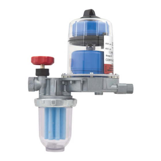
AFRISO FloCo-Top-1K Betriebsanleitung
Automatischer heizölentlüfter
mit integriertem filter
Vorschau ausblenden
Andere Handbücher für FloCo-Top-1K:
- Betriebsanleitung (162 Seiten) ,
- Betriebsanleitung (153 Seiten)
Inhaltsverzeichnis
Verfügbare Sprachen
Verfügbare Sprachen
Betriebsanleitung
Automatischer Heizölentlüfter
mit integriertem Filter
Version: 10.2018.0
ID: 900.000.0287
Copyright 2018 AFRISO-EURO-INDEX GmbH. Alle Rechte vorbehalten.
in Verbindung mit einem
PA-Schlauch 4 x 1 mm
FloCo-Top-1K
BRL A Teil 1
Telefon +49 7135-102-0
EN 12514-2
Service +49 7135-102-211
Telefax +49 7135-102-147
DE
Lindenstraße 20
74363 Güglingen
info@afriso.com
www.afriso.com
Inhaltsverzeichnis
Fehlerbehebung

Verwandte Anleitungen für AFRISO FloCo-Top-1K


Inhaltszusammenfassung für AFRISO FloCo-Top-1K
- Seite 1 Betriebsanleitung Automatischer Heizölentlüfter mit integriertem Filter FloCo-Top-1K Copyright 2018 AFRISO-EURO-INDEX GmbH. Alle Rechte vorbehalten. Lindenstraße 20 74363 Güglingen BRL A Teil 1 Telefon +49 7135-102-0 EN 12514-2 Service +49 7135-102-211 Telefax +49 7135-102-147 info@afriso.com in Verbindung mit einem Version: 10.2018.0 www.afriso.com...
- Seite 2 Über diese Betriebsanleitung Über diese Betriebsanleitung Diese Betriebsanleitung beschreibt den automatischen Heizölentlüfter mit integriertem Filter „FloCo-Top-1K“ (im Folgenden auch „Produkt“). Diese Betriebsanleitung ist Teil des Produkts. • Sie dürfen das Produkt erst benutzen, wenn Sie die Betriebsanleitung vollständig gelesen und verstanden haben.
-
Seite 3: Informationen Zur Sicherheit
Warnhinweise sind in dieser Betriebsanleitung mit Warnsymbolen und Sig- nalwörtern gekennzeichnet. Abhängig von der Schwere einer Gefährdungs- situation werden Warnhinweise in unterschiedliche Gefahrenklassen unter- teilt. HINWEIS HINWEIS macht auf eine möglicherweise gefährliche Situation aufmerksam, die bei Nichtbeachtung Sachschäden zur Folge haben kann. FloCo-Top-1K... - Seite 4 Führen Sie bei der Verwendung des Produkts alle Arbeiten ausschließlich unter den in der Betriebsanleitung und auf dem Typenschild spezifizierten Bedingungen und innerhalb der spezifizierten technischen Daten und in Übereinstimmung mit allen am Einsatzort geltenden Bestimmungen, Nor- men und Sicherheitsvorschriften durch. FloCo-Top-1K...
- Seite 5 Gefährdungen auftreten können, die nicht direkt vom Produkt ausge- hen. Veränderungen am Produkt Führen Sie ausschließlich solche Arbeiten an und mit dem Produkt durch, die in dieser Betriebsanleitung beschrieben sind. Nehmen Sie keine Verände- rungen vor, die in dieser Betriebsanleitung nicht beschrieben sind. FloCo-Top-1K...
-
Seite 6: Transport Und Lagerung
• Benutzen Sie für den Transport die Originalverpackung. • Lagern Sie das Produkt nur in trockener, sauberer Umgebung. • Stellen Sie sicher, dass das Produkt bei Transport und Lagerung stoßge- schützt ist. Nichtbeachtung dieser Anweisungen kann zu Sachschäden führen. FloCo-Top-1K... -
Seite 7: Produktbeschreibung
Heizöl und in kleineren Teilen aus Öl vom Tank, das noch Luftanteile enthält. A. Q Tank Düse B. Q Rücklauf C. Q Vorlauf D. Q Düse Zulassungsdokumente, Bescheinigungen, Erklärungen Das Produkt ist vom TÜV geprüft (Bericht Nummer S 133 2013 E2). FloCo-Top-1K... - Seite 8 Ölsäule von circa 8 m) Saugunterdruck Max. 0,5 bar Prüfdruck 6 bar Filtereinsatz 50-70µm Sinterkunststoff (Artikel 69960), sonstige Artikel siehe Verpackungsetikett Temperatureinsatzbereich Umgebung Max. +60 °C Medium Max. +60 °C Werkstoffe Entlüfterhaube Transparenter Kunststoff Filtertasse Transparenter Kunststoff Gehäuse Zink-Druckguss FloCo-Top-1K...
-
Seite 9: Montage
Filterverschmutzung sind 50 mbar an zusätzlichem Druckverlust berücksichtigt. Für den Druckverlust aufgrund der Rohrreibung ist die maximale Dichte von Heizöl EL von 860 kg/m und eine kinematische Viskosität von 6 mm /s ent- sprechend DIN 51603 zugrunde gelegt. FloCo-Top-1K... - Seite 10 Montage 5.2.1 Maximale Saugleitungslänge mit tieferliegendem Tankniveau 1. Entfernen Sie alle Rück- schlagventile vor dem Produkt, wenn die Saugleitung als selbstsi- chernde Saugleitung ent- sprechend dem gültigen, technischem Regelwerk verlegt ist. FloCo-Top-1K...
- Seite 11 > 100 > 100 15 kg/h Ø 6 mm (18 l/h) Ø 8 mm Ø 10 mm > 100 > 100 > 100 20 kg/h Ø 6 mm (24 l/h) Ø 8 mm Ø 10 mm > 100 > 100 FloCo-Top-1K...
- Seite 12 1. Montieren Sie ein Antihe- berventil, um ein Austre- ten (Aushebern) von Hei- zöl bei undichter Sauglei- tung und höher liegendem Ölstand im Tank zu ver- hindern. 1 = Kolben-Antiheberventil „KAV“ 2 = Membran-Antiheberventil „MAV“ = Relevante Saughöhe „KAV“ = Relevante Saughöhe „MAV“ FloCo-Top-1K...
- Seite 13 (6 l/h) 7,5 kg/h Ø 4 mm (9 l/h) Ø 6 mm 10 kg/h Ø 4 mm (12 l/h) Ø 6 mm 15 kg/h Ø 6 mm (18 l/h) 20 kg/h Ø 6 mm (24 l/h) Ø 8 mm FloCo-Top-1K...
- Seite 14 Kleber eindichten. Verwendung von Teflonband oder Hanf ist nicht zulässig. Nichtbeachtung dieser Anweisungen kann zu Sachschäden führen. 3. Dichten Sie die Saugleitung in das Innengewinde G des Gehäuses, mit zylindrischer Rohrverschraubung G nach DIN 3852 ein. Das Anzugs- moment beträgt 40 ±10 Nm. FloCo-Top-1K...
- Seite 15 Stellen Sie sicher, dass Sie den Vor- und Rücklaufanschluss nicht vertauscht anschließen. Nichtbeachtung dieser Anweisungen kann zu Sachschäden führen. Druckprüfung Stellen Sie sicher, dass der Druckanschluss bei der Saugleitungs-Druck- prüfung nicht am Produkt angeschlossen wird. Das integrierte Rück- schlagventil lässt die Druckübertragung auf die Saugleitung nicht zu. FloCo-Top-1K...
- Seite 16 Im Saugbetrieb mit sauberem Filtereinsatz A. Siku-Einsatz 35 µm B. Siku-Einsatz 70 µm C. Filz D. Stahlsieb Durchfluss Q [l/h] 5.5.2 Im Saugbetrieb mit 50 % verschmutztem Filtereinsatz 1. Siku-Einsatz 35 µm 2. Siku-Einsatz 70 µm 3. Filz 4. Stahlsieb Durchfluss Q [l/h] FloCo-Top-1K...
- Seite 17 Montage Entlüftungsschlauch anschließen A. Schlauchanschluss mit O-Ring B. Entlüftungsschlauch 1. Entfernen Sie die Abdeckkappe mit einem Schraubendreher. FloCo-Top-1K...
- Seite 18 6. Bringen Sie das andere Ende des Entlüftungsschlauchs an der Ent- lüftungsleitung oder am Rücklau- fanschluss der Entnahmearmatur des Tanks an, um einen eventuel- len Leitungsverschluss vorzubeu- gen. Der Anschluss an den Rücklaufanschluss der Entnahmearmatur kann mit der beiliegenden Schlauchtülle vorgenommen werden. FloCo-Top-1K...
-
Seite 19: Betrieb
Stellen Sie sicher, dass Sie unterhalb der Brennerschläuche und des Ölentlüfters eine Auffangwanne aufstellen, über welche ein möglicher Ölaustritt detektiert wird, sowie eine Abschaltung des Brenners erfolgt. Verwenden Sie ein „Flow-Control 3/K HT“ mit vorgeschaltetem Filter und Messing-Filtertasse oder Wechselfilterkartusche, wenn anlagenbedingt ein Heizölentlüfter benötigt wird. FloCo-Top-1K... - Seite 20 (1 bar Außendruck). Nach einem Hochwasserereignis ist das Produkt weiterhin funktionsfähig. Bei einem Produkt ohne Entlüftungsschlauch kann kein Heizöl austreten. Es kann aber Schmutzwasser in das Produkt eintreten. Deshalb muss ein Pro- dukt ohne Entlüftungsschlauch nach einem Hochwasserereignis ausge- tauscht werden. FloCo-Top-1K...
-
Seite 21: Wartung
Reinigen Sie die Kunststoffteile mit einer wässri- gen Seifenlauge Jährlich oder bei Bedarf Tauschen Sie den Filtereinsatz Alle 5 Jahre Ersetzen Sie die Brennerschläuche Spätestens nach 20 Tauschen Sie das Produkt aus Jahren Nach Hochwasser Tauschen Sie das Produkt aus FloCo-Top-1K... - Seite 22 Wartung Filtereinsatz tauschen 7.2.1 Filtereinsatz ausbauen FloCo-Top-1K...
- Seite 23 Wartung FloCo-Top-1K...
- Seite 24 Wartung 7.2.2 Filtereinsatz einbauen FloCo-Top-1K...
-
Seite 25: Störungsbeseitigung
Saugleitung durch zu tung korrekt aus (siehe ners großen Leitungs-Ø der Kapitel "Saugleitungs- Saugleitung. Beim Öff- länge ermitteln") nen des Antiheberven- tils nach der Vorbelüf- tungszeit des Brenners kann eine größere Blase durchschlagen, die eine Störabschal- tung verursachen kann FloCo-Top-1K... - Seite 26 Ölentlüfters durch Brennerpumpe erzeugt Führen Sie eine Saug- kein ausreichendes druckprüfung an der Vakuum Pumpe durch. Die Pumpe muss mindes- tens einen Unterdruck von -0,4 bar aufbauen Sonstige Störungen Bitte wenden Sie sich an die AFRISO-Service Hotline FloCo-Top-1K...
-
Seite 27: Außerbetriebnahme Und Entsorgung
2. Entsorgen Sie das Produkt. Rücksendung Vor einer Rücksendung Ihres Produkts müssen Sie sich mit uns in Verbin- dung setzen. Gewährleistung Informationen zur Gewährleistung finden Sie in unseren Allgemeinen Geschäftsbedingungen im Internet unter www.afriso.com oder in Ihrem Kauf- vertrag. FloCo-Top-1K... -
Seite 28: Ersatzteile Und Zubehör
Verwenden Sie nur Original Ersatz- und Zubehörteile des Herstellers. Nichtbeachtung dieser Anweisung kann zu Sachschäden führen. Produkt Artikelbezeichnung Art.-Nr. Abbildung Automatischer Heizölent- 69960 lüfter mit integriertem Filter „FloCo-Top-1K“ Ersatzteile und Zubehör Artikelbezeichnung Art.-Nr. Abbildung Filtertasse kurz (Standard) 20254 Filtertasse kurz 20257 (mit Entleereinrichtung) O-Ring für Filtertasse... - Seite 29 DIN 3852 mit Kupfer-Flach- dichtung: Rohr Ø 6 mm 20509 Rohr Ø 8 mm 20508 Rohr Ø 10 mm 20510 Rohr Ø 12 mm 20512 Kolben-Antiheberventil 20240 „KAV“ Membran-Antiheberventil 20139 „MAV“ Entlüftungsschlauch, 20696 PVC, Ø 4 x 1 mm, 20 m Rolle FloCo-Top-1K...
- Seite 30 Ersatzteile und Zubehör FloCo-Top-1K...