BS 8802B Bedienungsanleitung
Verfügbare Sprachen
Verfügbare Sprachen

Verwandte Anleitungen für BS 8802B

Inhaltszusammenfassung für BS 8802B
- Seite 1 Bedienungsanleitung Instruction Manual 8802B...
- Seite 2 Inhalt/Contents Produktbeschreibung............1 Gebrauchshinweise und technische Daten ....2 Montageanleitung ..............3 Product description ............... 1 Instructions for use and technical data ......8 Assembly instructions ............9...
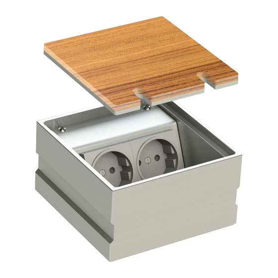
- Seite 3 8802B Bezeichnung/Designation: Deckel/Lid Geräteträger/Device carrier Steckdose/Socket Gehäuse/Housing...
-
Seite 4: Technische Daten
Art.-Nr. Abmessungen Zuleitungen Nivellierbar Schutzart Belastbarkeit 125 x125 x 2 x hinten, Flächenlast 8802B 5 mm IP20 70 mm Ø 25 mm max. 300 kg Gebrauchshinweise • Bei Verwendung der Nivellierschrauben zur Höhenkorrektur des Deckels ist die Um eine anhaltende Funktion der Boden- Bodensteckdose nur begehbar. - Seite 5 Montageanleitung Schritt 1 Schritt 2 (Vorbereitungen) Den Deckel abnehmen. Anschließend Vor dem Gießen des Estrichs einen den Geräteträger von dem Gehäuse Polystyrol-Block (PB), der in seiner abmontieren. äußeren Abmessung umlaufend ca. 40 mm größer ist als die Dose*, als Platzhalter auf die ausgelegte Dämmschicht (P) kleben.
- Seite 6 Schritt 3 Nach dem Gießen des Estrichs den Polystyrol- Block (PB) aus dem Estrich entfernen. Das Gehäuse nun in die entstandene Bodenaussparung auf ein Mörtelbett* (M) einsetzen und die Leerrohre in die Öffnungen des Gehäuses einführen.
- Seite 7 *Achtung! Die Höhe des Mörtelbetts (M) muss so vermessen werden, dass die Wasserwaage (W) und der Estrich (E) bündig sind (fluchtend sind)! Zudem muss das Mörtelbett für die entsprechende Belastung des Boden- steckdose ausgelegt sein.
- Seite 8 Schritt 4 Das Gehäuse abdichten. (Tipp: die Gehäuseöffnung beispielsweise mit Pappe abdecken, nicht abgebildet.) Die Aussparung um das Gehäuse nun mit Mörtel (M) auffüllen. Die Position des Gehäuses vor dem Aushärten des Mörtels mit der Wasserwaage (W) überprüfen!
- Seite 9 Schritt 5 Nach dem Aushärten die Steckdosen und einsetzen. Den restlichen Belag (B) anschließen, den Geräteträger im Raum verlegen. wieder in das Gehäuse einschrauben. Die Bodensteckdose ist nun erfolgreich Den Deckel mit Belag (B) bekleben eingebaut. (Siehe Querschnitt unten.)