Allen-Bradley SLC 5/03 Installationsanleitung
Modulare prozessoren
Vorschau ausblenden
Andere Handbücher für SLC 5/03:
- Installationsanleitung (88 Seiten) ,
- Installationsanleitung (76 Seiten) ,
- Installationsanleitung (12 Seiten)
Inhaltsverzeichnis
Werbung
Verfügbare Sprachen
Verfügbare Sprachen
Quicklinks
SLC 5/03™, SLC 5/04™, and SLC 5/05™
Modular Processors
(Catalog Numbers 1747-L531, 1747-L532,
1747-L541, 1747-L542, 1747-L543,
1747-L551, 1747-L552, 1747-L553)
To
Install your chassis
Installation du châssis
Installation des Chassis
Installazione dello chassis
Instalar el chasis
Instalar o chassi
Install your power supply
Installation de l'alimentation
Installation des Netzteils
Installazione dell'alimentatore
Instalar la fuente de alimentación eléctrica
Instalar a fonte de energia
Install your processor
Installation de processeur
Installation des Prozessors
Installazione del processore
Instalar el procesador
Instalar o processador
English Section .................................... 3
Section en français............................ 15
Deutscher Abschnitt .......................... 27
Sezione italiana ................................. 39
Sección en español............................ 51
Seção em português.......................... 63
Installation Instructions
Use Publication
1746-5.8
1746-IN004A-ML-P
1747-IN009A-ML-P
Publication 1747-IN009A-ML-P
Werbung
Kapitel
Inhaltsverzeichnis
Fehlerbehebung

Verwandte Anleitungen für Allen-Bradley SLC 5/03


Inhaltszusammenfassung für Allen-Bradley SLC 5/03
- Seite 1 Installation Instructions SLC 5/03™, SLC 5/04™, and SLC 5/05™ Modular Processors (Catalog Numbers 1747-L531, 1747-L532, 1747-L541, 1747-L542, 1747-L543, 1747-L551, 1747-L552, 1747-L553) Use Publication Install your chassis 1746-5.8 Installation du châssis Installation des Chassis Installazione dello chassis Instalar el chasis Instalar o chassi...
- Seite 2 SLC 5/03™, SLC 5/04™, and SLC 5/05™ Modular Processors Publication 1747-IN009A-ML-P...
-
Seite 3: Inhaltsverzeichnis
Installation Instructions English Section SLC 5/03™, SLC 5/04™, and SLC 5/05™ Modular Processors (Catalog Numbers 1747-L531, 1747-L532, 1747-L541, 1747-L542, 1747-L543, 1747-L551, 1747-L552, 1747-L553) Inside… ..................page Important User Information..............4 For More Information ................5 Required Tools and Equipment............. 6 Safety Considerations ................6 Installation Procedure ................ -
Seite 4: Important User Information
SLC 5/03™, SLC 5/04™, and SLC 5/05™ Modular Processors Important User Information Because of the variety of uses for the products described in this publication, those responsible for the application and use of this control equipment must satisfy themselves that all necessary steps have been taken to assure that each application and use meets all performance and safety requirements, including any applicable laws, regulations, codes and standards. -
Seite 5: For More Information
SLC 5/03™, SLC 5/04™, and SLC 5/05™ Modular Processors For More Information As part of our effort to preserve, protect, and improve our environment, Allen- Bradley is reducing the amount of paper we use. Less paper means more options for you. -
Seite 6: Required Tools And Equipment
SLC 5/03™, SLC 5/04™, and SLC 5/05™ Modular Processors Required Tools and Equipment • medium blade screwdriver • programming equipment • a 1747-PIC, 1784-KTX, or 1784-PCMK communication interface (or standard Ethernet PC board - SLC 5/05 only) Safety Considerations ATTENTION: Never install, remove, or wire any module while power is applied. -
Seite 7: Installation Procedure
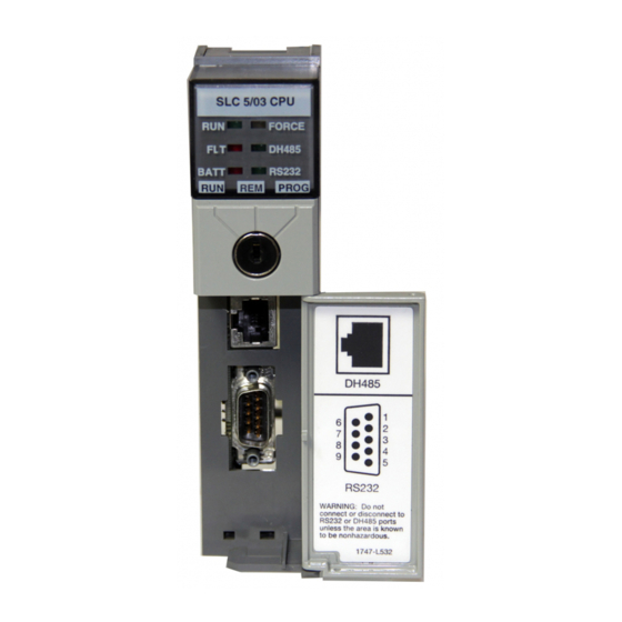
SLC 5/03™, SLC 5/04™, and SLC 5/05™ Modular Processors Installation Procedure Install the Processor Make sure system power is off; then insert the processor into slot 0 of the 1746 chassis. Important: The SLC 500 modular processors must be inserted into the left slot (slot 0), as shown below. - Seite 8 SLC 5/03™, SLC 5/04™, and SLC 5/05™ Modular Processors Power Supply and LED Indicators Indicates the LED is OFF FORCE POWER Indicates the LED is ON DH485 Indicates the LED is FLASHING BATT RS232 Status of LED does not matter...
-
Seite 9: Replacing The Battery
SLC 5/03™, SLC 5/04™, and SLC 5/05™ Modular Processors 2. Set the communication parameters of the software to match the default parameters of the processor: Channel 0 Configuration Channel 1 Configuration SLC 5/03, 5/04, 5/05 SLC 5/03 SLC 5/04 SLC 5/05... - Seite 10 Left Side View Important: The SLC 5/03, 5/04, and 5/05 processors have a capacitor that provides at least 30 minutes of battery back-up while the battery is disconnected. Data in RAM is not lost if the battery is replaced within 30 minutes 4.
-
Seite 11: Troubleshooting
SLC 5/03™, SLC 5/04™, and SLC 5/05™ Modular Processors Troubleshooting Before troubleshooting your SLC 500 system, please obtain an SLC 500 Modular Hardware Style Installation and Operation Manual (1747-6.2) from one of the sources listed on page 5. Refer to the chapter on Troubleshooting. -
Seite 12: General Specifications
SLC 5/03™, SLC 5/04™, and SLC 5/05™ Modular Processors Communication Communication options for the SLC 5/03, 5/04, and 5/05 processors are as follows: • DH485 • RS-232 protocols (DF1 Full-Duplex, DF1 Half-Duplex “master/slave”, DH-485, or ASCII) • Data Highway Plus™... -
Seite 13: Memory Back Up
SLC 5/03™, SLC 5/04™, and SLC 5/05™ Modular Processors Memory Back Up The following table shows the memory back up options for the SLC 5/03, 5/04, and 5/05 processors. Flash EPROMs (Flash Erasable Programmable Read Only Memory) combine the versatility of EEPROMs (Electrically-Erasable Programmable Read Only Memory) with the security of UVPROMs (UV-Erasable PROM). - Seite 14 SLC 5/03™, SLC 5/04™, and SLC 5/05™ Modular Processors Shipment of depleted batteries for disposal may be subject to specific regulation of the countries involved or to regulations endorsed by those countries, such as the IATA Restricted Articles Regulations of the International Air Transport Association, Geneva, Switzerland.
- Seite 15 Notice d’installation Section en français Processeurs modulaires SLC 5/03™, SLC 5/04™ et SLC 5/05™ (Références 1747-L531 1747-L532, 1747-L541, 1747-L542, 1747-L543, 1747-L551, 1747-L552, 1747-L553) Contenu… ..................page Informations utilisateur..............16 Complément d’informations............... 17 Outils et équipement requis............... 18 Considérations de sécurité..............18 Procédure d’installation ..............
-
Seite 16: Informations Utilisateur
Les illustrations, schémas et exemples de programmes contenus dans ce manuel sont présentés à titre indicatif seulement. En raison des nombreuses variables et impératifs associés à chaque installation, la société Allen-Bradley ne saurait être tenue pour responsable ou redevable (y compris en matière de propriété intellectuelle) des suites d’utilisation réelle basée sur les exemples et schémas présentés dans ce manuel. -
Seite 17: Complément D'informations
Complément d’informations Dans le cadre des efforts de protection, de sauvegarde et d’amélioration de l’environnement, Allen-Bradley réduit la quantité de papier utilisé. Moins de papier, c’est aussi un plus grand choix pour les utilisateurs : outre les publications imprimées traditionnelles et versions sur CD-ROM, nous vous offrons maintenant des manuels en ligne comportant les informations les plus récentes. -
Seite 18: Outils Et Équipement Requis
Processeurs modulaires SLC 5/03™, SLC 5/04™ et SLC 5/05™ Outils et équipement requis • un tournevis plat de taille moyenne • un équipement de programmation • une interface de communication 1747-PIC, 1784-KTX ou 1784-PCMK (ou une carte Ethernet PC standard - uniquement SLC 5/05) Considérations de sécurité... -
Seite 19: Procédure D'installation
Processeurs modulaires SLC 5/03™, SLC 5/04™ et SLC 5/05™ Procédure d’installation Installation du processeur Assurez-vous que l’alimentation est hors tension, puis insérez le processeur dans l’emplacement 0 du châssis 1746. Important : Les processeurs modulaires SLC 500™ doivent être insérés dans l’emplacement de gauche (emplacement 0), comme illustré... - Seite 20 Processeurs modulaires SLC 5/03™, SLC 5/04™ et SLC 5/05™ Voyants d’alimentation Indique que le voyant est eteint. POWER FORCE Indique que le voyant est allume. DH485 Indique que le voyant clignote. BATT RS232 L’etat du voyant n’a pas d’importance. SLC 5/03...
-
Seite 21: Remplacement De La Pile
Processeurs modulaires SLC 5/03™, SLC 5/04™ et SLC 5/05™ 2. Définissez les paramètres de communication du logiciel en fonction des paramètres par défaut du processeur : Configuration du canal 0 Configuration du canal 1 SLC 5/03, 5/04, 5/05 SLC 5/03... - Seite 22 Vue laterale gauche Important : Les processeurs SLC 5/03, SLC 5/04 et SLC 5/05 sont équipés d’un condensateur qui assure au moins 30 minutes de sauvegarde lorsque la pile est déconnectée. Les données contenues dans la RAM ne sont pas perdues si la pile est remplacée dans cet intervalle de 30 minutes.
-
Seite 23: Dépannage
Processeurs modulaires SLC 5/03™, SLC 5/04™ et SLC 5/05™ Dépannage Avant de commencer à dépanner votre système SLC 500, veuillez vous procurer le Manuel d’installation et de fonctionnement des SLC 500 modulaires (1747-6.2) auprès d’une des sources de documentation présentées en page 17. Référez-vous au chapitre relatif au dépannage. - Seite 24 Processeurs modulaires SLC 5/03™, SLC 5/04™ et SLC 5/05™ Communication Les options de communication des processeurs SLC 5/03, SLC 5/04 et SLC 5/05 sont les suivantes : • DH-485 • Protocoles RS-232 (DF1 Full-Duplex, DF1 Half–Duplex “maître/esclave”, DH-485 ou ASCII) •...
-
Seite 25: Sauvegarde De La Mémoire
Sauvegarde de la mémoire Le tableau suivant indique les options de sauvegarde de la mémoire pour les processeurs SLC 5/03, SLC 5/04 et SLC 5/05. Les EPROM Flash (Mémoire flash morte programmable électriquement) associent la souplesse des EEPROM à la sécurité... - Seite 26 Processeurs modulaires SLC 5/03™, SLC 5/04™ et SLC 5/05™ ferrovière, maritime et avion cargo sous certaines conditions. Le transport par avion passager est interdit. L’expédition de piles déchargées pour mise au rebut est soumise aux réglements spécifiques du pays concerné ou aux réglements avalisés par lesdits pays, tels que lmes réglementations d’articles restrictifs de l’IATA (l’International Air Transport...
-
Seite 27: Modulare Prozessoren Slc 5/03™ Slc 5/04™ Und Slc
Installationsanleitung Deutscher Abschnitt Modulare Prozessoren SLC 5/03™ SLC 5/04™ und SLC 5/05™ (Bestellnummern 1747-L531, 1747-L532, 1747-L541, 1747-L542, 1747-L543, 1747-L551, 1747-L552, 1747-L553) Inhalt… ....................Seite Wichtige Anwendungshinweise ..............28 Weitere Informationen ................29 Erforderliche Werkzeuge und Geräte ............30 Sicherheitshinweise................... 30 Einbauverfahren .................. -
Seite 28: Wichtige Anwendungshinweise
Modulare Prozessoren SLC 5/03™ SLC 5/04™ und SLC 5/05™ Wichtige Anwendungshinweise Aufgrund der vielfältigen Einsatzmöglichkeiten der in dieser Publikation beschriebenen Produkte müssen Sie als Verantwortlicher für die Anwendung und Nutzung dieses Geräts sicherstellen, daß jede Anwendung bzw. jeder Einsatz alle Leistungs- und Sicherheitsanforderungen, einschließlich sämtlicher anwendbaren... -
Seite 29: Weitere Informationen
Weitere Informationen In unseren Bemühungen, die Umwelt zu erhalten, zu schützen und zu verbessern, reduzieren wir bei Allen-Bradley die Papiermenge, die wir einsetzen. Weniger Papier bedeutet mehr Alternativen für Sie. Neben den herkömmlichen gedruckten Publikationen bieten wir nun Online-Handbücher an, die aktuellste Daten enthalten. -
Seite 30: Erforderliche Werkzeuge Und Geräte
Modulare Prozessoren SLC 5/03™ SLC 5/04™ und SLC 5/05™ Erforderliche Werkzeuge und Geräte • mittelgroßer Flachschraubendreher • Programmiergerät • Kommunikationsschnittstelle 1747-PIC, 1784-KTX oder 1784-PCMK (oder standardmäßige Ethernet-PC-Platine - nur SLC 5/05) Sicherheitshinweise ACHTUNG: Ein Modul darf niemals bei anliegender Spannung installiert, entfernt oder verdrahtet werden. -
Seite 31: Einbauverfahren
Modulare Prozessoren SLC 5/03™ SLC 5/04™ und SLC 5/05™ Einbauverfahren Einbau des Prozessors Vergewissern Sie sich, daß die Systemspannung ausgeschaltet ist, und schieben Sie den Prozessor anschließend in Steckplatz 0 des Chassis der Reihe 1746. Wichtig: Die modularen Prozessoren der Reihe SLC 500t müssen, wie unten dargestellt, in den linken Steckplatz (Steckplatz 0) eingeschoben werden. -
Seite 32: Laden Der Software
Modulare Prozessoren SLC 5/03™ SLC 5/04™ und SLC 5/05™ Netzteil und LED-Anzeigen LED AUS FORCE POWER LED LEUCHTET DH485 LED BLINKT BATT RS232 LED-Status ist unbedeutend SLC 5/03 POWER FORCE POWER FORCE ENET BATT RS232 BATT RS232 SLC 5/04 SLC 5/05 Laden der Software Hinweise sind in den Handbüchern der Programmiersoftware enthalten. -
Seite 33: Auswechseln Der Batterie
Modulare Prozessoren SLC 5/03™ SLC 5/04™ und SLC 5/05™ 2. Die Kommunikationsparameter der Software so einstellen, daß sie mit den Vorgabewerten des Prozessors übereinstimmen: Konfiguration : Kanal 0 Konfiguration: Kanal 1 SLC 5/03, 5/04, 5/05 SLC 5/03 SLC 5/04 SLC 5/05... - Seite 34 Seitenansicht Wichtig: Die Prozessoren SLC 5/03, SLC 5/04 und SLC 5/05 sind mit einem Kondensator ausgestattet, der einen mindestens 30 Minuten langen Batterie-Backup gewährleistet, während die Batterie nicht angeschlossen ist. Die Daten im RAM-Speicher gehen somit nicht verloren, wenn die Batterie innerhalb von 30 Minuten ausgewechselt wird.
-
Seite 35: Störungssuche
0,44 µs 0,37 µs Programmiersoftware SLC 5/03 und SLC 5/04: RSLogix 500™, PLC-500 A.I. Series™ SLC 5/05: RSLogix 500™ (1) Die Abfragezeiten beziehn sich generell auf ein Kontaktplanprogram (1K) das aus einfacher Strompfadlogik und Kommunikationsbefehlen besteht. Die tatsachlichen Abfragezeiten hangen von der Programmgrosse, den programmierten Befehlen und dem Kommunikationsprotokoll ab. -
Seite 36: Allgemeine Technische Daten
Modulare Prozessoren SLC 5/03™ SLC 5/04™ und SLC 5/05™ Kommunikation Für die Prozessoren SLC 5/03, SLC 5/04 und SLC 5/05 stehen die folgenden Kommunikationsoptionen zur Verfügung: • DH-485 • RS-232-Protokolle (DF1-Vollduplex, DF1-Halbduplex “Master/Slave”, DH-485 oder ASCII) • Data Highway Plust (für die Prozessoren SLC 5/03 und SLC 5/05 ist ein 1785-KA5 erforderlich) -
Seite 37: Handhabung, Lagerung Und Transport Der Batterie (Best.-Nr. 1747-Ba)
Modulare Prozessoren SLC 5/03™ SLC 5/04™ und SLC 5/05™ Speicher- SLC 5/03 SLC 5/04 SLC 5/05 Backup-Option (1747-L531, -L532) (1747-L541, -542, -543) (1747-L551, -552, -553) Flash EPROM 1747-M11 1747-M11 1747-M11 1747-M12 (nur OS302+) 1747-M12 (nur OS401+) 1747-M12 Handhabung, Lagerung und Transport der Batterie (Best.-Nr. - Seite 38 Modulare Prozessoren SLC 5/03™ SLC 5/04™ und SLC 5/05™ Der Versand von verbrauchten Batterien unterliegt den jeweiligen Bestimmungen des Landes oder den Bestimmungen des Internationalen Lufttransportverbands in Genf (IATA-Regelung bezüglich des Versands von Gefahrengütern). Wichtig: Die auf den Transport von Lithiumbatterien zutreffenden Bestimmungen werden von Zeit zu Zeit neu überarbeitet.
-
Seite 39: Istruzioni Per L'installazione
Istruzioni per l’installazione Sezione italiana Processori modulari SLC 5/03™ SLC 5/04™ e SLC 5/05™ (Numeri di catalogo 1747-L531, 1747-L532, 1747-L541, 1747-L542, 1747-L543, 1747-L551, 1747-L552, 1747-L553) All’interno…................pagina Informazioni importanti per l’utente..........40 Per ulteriori informazioni ..............41 Strumenti ed apparecchiature necessari .......... 42 Considerazioni sulla sicurezza ............ -
Seite 40: Informazioni Importanti Per L'utente
Le illustrazioni, gli schemi, i programmi campione e gli esempi di configurazioni di questo manuale sono intesi esclusivamente ad illustrare il testo. A causa dei numerosi requisiti e variabili propri di ciascuna installazione, la Allen-Bradley declina ogni responsabilità (compresa la responsabilità per la proprietà intellettuale) per l’uso dei prodotti basato sulle applicazioni illustrate in questa pubblicazione. -
Seite 41: Per Ulteriori Informazioni
Per ulteriori informazioni Nell’ambito dell’impegno profuso per preservare, proteggere e migliorare il nostro ambiente, la Allen-Bradley sta gradualmente riducendo la quantità di carta utilizzata. Una minore quantità di carta significa maggiori opportunità per l’utente. Oltre alle tradizionali pubblicazioni su carta, la Allen-Bradley offre ora manuali in linea contenenti tutte le informazioni più... -
Seite 42: Strumenti Ed Apparecchiature Necessari
Processori modulari SLC 5/03™ SLC 5/04™ e SLC 5/05™ Strumenti ed apparecchiature necessari • cacciavite a taglio medio • apparecchiatura di programmazione • interfaccia di comunicazione 1747-PIC, 1784-KTX o 1784-PCMK (oppure scheda PC standard Ethernet - solo SLC 5/05) Considerazioni sulla sicurezza ATTENZIONE: non installare, rimuovere o collegare i moduli quando sono alimentati. -
Seite 43: Procedura Di Installazione
Processori modulari SLC 5/03™ SLC 5/04™ e SLC 5/05™ Procedura di installazione Installazione del processore Assicurarsi che il sistema non sia alimentato, quindi inserire il processore nello slot 0 dello chassis 1746. Importante: il processore modulare SLC 500™ deve essere inserito nello slot di sinistra (slot 0), come illustrato nella seguente figura. - Seite 44 Processori modulari SLC 5/03™ SLC 5/04™ e SLC 5/05™ Alimentore ed indicatori LED Indica che il LED e OFF POWER FORCE Indica che il LED e ON. DH485 Indica che il LED e LAMPEGGIANTE. BATT RS232 Lo stato del LED non ha importanza...
-
Seite 45: Sostituzione Della Batteria
Processori modulari SLC 5/03™ SLC 5/04™ e SLC 5/05™ 2. Impostare i parametri di comunicazione del software per farli corrispondere ai parametri predefiniti del processore: Configurazione Canale 0 Configurazione Canale 1 SLC 5/03, 5/04, 5/05 SLC 5/03 SLC 5/04 SLC 5/05... - Seite 46 Importante: i processori SLC 5/03, 5/04 e 5/05 hanno un capacitore che fornisce almeno 30 minuti di back up alla batteria mentre la batteria è scollegata. Se la batteria viene sostituita entro 30 minuti i dati nella RAM non vengono persi.
-
Seite 47: Individuazione Dei Guasti
Processori modulari SLC 5/03™ SLC 5/04™ e SLC 5/05™ Individuazione dei guasti Prima di procedere all’individuazione dei guasti del sistema SLC 500, procurarsi una copia del manuale SLC 500 Modular Hardware Style Installation and Operation Manual (1747-6.2) in uno dei modi illustrati alla pagina 41 e fare riferimento al capitolo sull’individuazione dei guasti. -
Seite 48: Caratteristiche Tecniche Generali
CE per tutte le direttive applicabili Back Up della memoria La seguente tabella elenca le opzioni di back up per i processori SLC 5/03, 5/04 e 5/05. Le EPROM flash (Flash Erasable Programmable Read Only Memory) combinano la versatilità delle EEPROM con la sicurezza delle UVPROM. -
Seite 49: Utilizzo, Stoccaggio E Trasporto Della Batteria (No. Cat. 1747-Ba)
Processori modulari SLC 5/03™ SLC 5/04™ e SLC 5/05™ Opzione memoria SLC 5/03 SLC 5/04 SLC 5/05 di back up (1747-L531, -L532) (1747-L541, -542, -543) (1747-L551, -552, -553) EPROM Flash 1747-M11 1747-M11 1747-M11 1747-M12 (solo OS302+) 1747-M12 (solo OS401+) 1747-M12 Utilizzo, stoccaggio e trasporto della batteria (No. - Seite 50 Processori modulari SLC 5/03™ SLC 5/04™ e SLC 5/05™ le Restricted Articles Regulations dello IATA (International Air Transport Association), Ginevra, Svizzera. Importante: le normative per il trasporto delle batterie al litio vengono periodicamente aggiornate. ATTENZIONE: le batterie al litio non devono essere bruciate né...
- Seite 51 Instrucciones de instalación Sección en español Procesadores modulares SLC 5/03™, SLC 5/04™ y SLC 5/05™ (Números de catálogo 1747-L531, 1747-L532, 1747-L541, 1747-L542, 1747-L543, 1747-L551, 1747-L552, 1747-L553) Contenido… ................página Información importante para el usuario..........52 Para obtener más información ............53 Herramientas y equipo necesarios............
-
Seite 52: Información Importante Para El Usuario
Está prohibida la reproducción total o parcial del contenido de esta publicación de propiedad exclusiva sin el permiso por escrito de Allen-Bradley Company, Inc. En estas instrucciones de instalación hacemos anotaciones para alertarle de consideraciones de seguridad: ATENCION: Identifica información sobre prácticas o circunstancias... -
Seite 53: Para Obtener Más Información
Para obtener más información Como parte de nuestro esfuerzo para preservar, proteger y mejorar nuestro medio ambiente, Allen-Bradley está reduciendo la cantidad de papel que usa. Menos papel significa más opciones para usted. Además de las publicaciones impresas tradicionales, ahora ofrecemos manuales en línea con la información más actualizada disponible. -
Seite 54: Herramientas Y Equipo Necesarios
Procesadores modulares SLC 5/03™, SLC 5/04™ y SLC 5/05™ Herramientas y equipo necesarios • destornillador de hoja mediana • equipo de programación • interfaces de comunicación 1747-PIC, 1784-KTX ó 1784-PCMK (o tarjeta PC Ethernet estándar - SLC 5/05 solamente) Consideraciones de seguridad ATENCION: Nunca instale, retire o cablee los módulos mientras... -
Seite 55: Procedimiento De Instalación
Procesadores modulares SLC 5/03™, SLC 5/04™ y SLC 5/05™ Procedimiento de instalación Instalación del procesador Asegúrese de que la alimentación eléctrica del sistema esté deconectada; luego inserte el procesador en la ranura 0 del chasis 1746. Importante: Los procesadores modulares SLC 500™ deben insertarse en la ranura izquierda (ranura 0), como se muestra a continuación. - Seite 56 Procesadores modulares SLC 5/03™, SLC 5/04™ y SLC 5/05™ Fuente de alimentacion electrica e indicadores LED Indica que el LED esta APAGADO. POWER FORCE Indica que el LED esta ILUMINADO DH485 Indica que el LED PARPADEA. BATT RS232 El estado del LED no importa.
-
Seite 57: Reemplazo De La Batería
Procesadores modulares SLC 5/03™, SLC 5/04™ y SLC 5/05™ 2. Establezca los parámetros de comunicación del software a los mismos valores que los parámetros predeterminados del procesador: Configuración de canal 0 Configuración de canal 1 SLC 5/03, 5/04, 5/05 SLC 5/03... - Seite 58 Vista del lado izquierdo Importante: Los procesadores SLC 5/03, 5/04 y 5/05 tienen un capacitor que proporciona por lo menos 30 minutos de seguridad de batería de respaldo mientras la batería está desconectada. Los datos en la RAM no se pierden si la batería se reemplaza antes de los 30 minutos.
-
Seite 59: Localización Y Corrección De Fallos
Procesadores modulares SLC 5/03™, SLC 5/04™ y SLC 5/05™ Localización y corrección de fallos Antes de localizar y corregir fallos del sistema SLC 500, por favor consiga un Manual de instalación y operación del hardware estilo modular SLC 500 (1747-6.2) de uno de los proveedores listados en la página 53. -
Seite 60: Especificaciones Generales
500 mA para el procesador SLC 5/03 1.0 A para los procesadores SLC 5/04 y 5/05 Fuente de alimentación cargando a 24 VCC 175 mA para el procesador SLC 5/03 200 mA para los procesadores SLC 5/04 y 5/05 Tiempo de retención del escán de programa 20 ms a 3 s (dependiendo de la carga de la fuente de después de pérdida de alimentación... -
Seite 61: Manipulación, Almacenamiento Y Transporte De La Batería
Procesadores modulares SLC 5/03™, SLC 5/04™ y SLC 5/05™ Opción de copia de SLC 5/03 SLC 5/04 SLC 5/05 seguridad (backup) (1747-L531, -L532) (1747-L541, -542, -543) (1747-L551, -552, -553) de memoria Flash EPROM 1747-M11 1747-M11 1747-M11 1747-M12 (OS302+ 1747-M12 (OS401+... - Seite 62 Procesadores modulares SLC 5/03™, SLC 5/04™ y SLC 5/05™ como los Reglamentos de artículos restringidos IATA de la Asociación de transporte aéreo internacional, Ginebra, Suiza. Importante: Los reglamentos para el transporte de baterías de litio se revisan periódicamente. ATENCION: No incinere ni deseche las baterías de litio en tiraderos de basura generales.
-
Seite 63: Instruções De Instalação
Instruções de Instalação Seção em português Controladores de Estrutura Modular SLC 5/03™, SLC 5/04™ e SLC 5/05™ (Códigos de Catálogo 1747-L531, 1747-L532, 1747-L541, 1747-L542, 1747-L543, 1747-L551, 1747-L552, 1747-L553) Índice…....................página Informações Importantes para o Usuário............64 Para Obter Mais Informações ................65 Ferramentas e Equipamentos Necessários............ -
Seite 64: Informações Importantes Para O Usuário
Controladores de Estrutura Modular SLC 5/03™, SLC 5/04™ e SLC 5/05™ Informações Importantes para o Usuário Devido à variedade de emprego dos produtos descritos nesta publicação, as pessoas responsáveis pela aplicação e uso deste equipamento de controle devem certificar-se de que todos os passos necessários foram adotados, para garantir que cada aplicação e uso satisfaz todos os requisitos de desempenho e segurança, incluindo quaisquer leis,... -
Seite 65: Para Obter Mais Informações
Controladores de Estrutura Modular SLC 5/03™, SLC 5/04™ e SLC 5/05™ Para Obter Mais Informações Como parte do nosso esforço para preservar, proteger e melhorar o ambiente, a Rockwell Automation está reduzindo a quantidade de papel utilizada. Menos papel significa mais opções para você. Além das publicações tradicionais impressas e versões em CD-ROM, hoje oferecemos manuais on-line contendo as informações... -
Seite 66: Ferramentas E Equipamentos Necessários
Controladores de Estrutura Modular SLC 5/03™, SLC 5/04™ e SLC 5/05™ Ferramentas e Equipamentos Necessários • Chave de fenda média • Equipamento de programação • Uma interface de comunicação 1747-PIC, 1784-KTX ou 1784-PCMK (ou uma placa Ethernet PC padrão - apenas SLC 5/05) Considerações de Segurança... -
Seite 67: Procedimento De Instalação
Controladores de Estrutura Modular SLC 5/03™, SLC 5/04™ e SLC 5/05™ Procedimento de Instalação Instale o Controlador Certifique-se de que a alimentação do sistema esteja desligada; a seguir, instale o controlador no slot 0 do chassi 1746. Importante: Os controladores de estrutura modular SLC 500 devem ser inseridos no slot esquerdo (slot 0), como exibido abaixo. - Seite 68 Controladores de Estrutura Modular SLC 5/03™, SLC 5/04™ e SLC 5/05™ Fonte de alimentacao e indicadores LED Indica que o LED esta DESLIGADO. FORCE POWER Indica que o LED esta LIGADO. DH485 Indica que o LED esta PISCANDO BATT RS232 O status do LED nao importa.
-
Seite 69: Substituição Da Bateria
Controladores de Estrutura Modular SLC 5/03™, SLC 5/04™ e SLC 5/05™ 2. Defina os parâmetros de comunicação do software para corresponder aos parâmetros default do controlador: Configuração do Canal 0 Configuração do Canal 1 SLC 5/03, 5/04, 5/05 SLC 5/03... - Seite 70 Vista Lateral Esquerda Importante: Os controladores SLC 5/03, 5/04 e 5/05 têm um capacitor que fornece pelo menos 30 minutos de alimentação reserva com a bateria desligada. Os dados da memória RAM não serão perdidos caso a bateria seja substituída em menos de 30 minutos.
-
Seite 71: Localização De Falhas
Controladores de Estrutura Modular SLC 5/03™, SLC 5/04™ e SLC 5/05™ Localização de Falhas Antes de tentar localizar falhas no SLC 500, consulte o capítulo sobre Localização de Falhas do SLC 500 Modular Hardware Style Installation and Operation Manual (1747-6.2). -
Seite 72: Especificações Gerais
Controladores de Estrutura Modular SLC 5/03™, SLC 5/04™ e SLC 5/05™ Comunicação As opções de comunicação dos controladores SLC 5/03, 5/04 e 5/05 são as seguintes: • DH-485 • Protocolos RS-232 (DF1 Full-Duplex, DF1 Half Duplex “mestre/escravo”, DH-485 ou ASCII) •... -
Seite 73: Manuseio, Armazenamento E Transporte Da Bateria (Cód. Cat. 1747-Ba)
Controladores de Estrutura Modular SLC 5/03™, SLC 5/04™ e SLC 5/05™ Backup de Memória Na tabela a seguir são exibidas as opções de backup de memória dos controladores SLC 5/03, 5/04 e 5/05. As EPROMs instantâneas (“Flash Erasable Programmable Read Only Memory”, Memória Exclusiva de Leitura Programável e Apagável Instantânea) combinam a versatilidade das EEPROMS com a segurança das... - Seite 74 Controladores de Estrutura Modular SLC 5/03™, SLC 5/04™ e SLC 5/05™ sejam satisfeitas algumas condições. O transporte em aviões de passageiros não é permitido. A remessa de baterias descarregadas para transporte pode ficar sujeita a normas específicas dos países envolvidos ou a normas endossadas por estes países, como as Normas de Artigos Restritos da IATA, da Associação Internacional de Transoporte...
- Seite 75 Publication 1747-IN009A-ML-P...
- Seite 76 PLC-5 is a registered trademark of Rockwell Automation. SLC 500, SLC 5/03, SLC 5/04, SLC 5/05, and Data Highway Plus, RSLogix 500, and PLC-500 A.I. Series are trademarks of Rockwell Automation. Ethernet is a registered trademark of Digital Equipment Corporation, Intel, and Xerox Corporation.