Werbung
Quicklinks
POSICONTROL
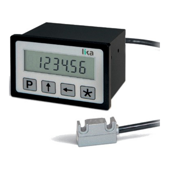
Battery powered LCD displays
LD111 • LD112
Series
Complete documentation
available for download at www.lika.biz
Warning: devices having order code ending with "/Sxxx" may have mechanical and electrical characteristics different from standard and be supplied with additional documentation for special connections (Technical Info).
Attenzione: i dispositivi con codice di ordinazione finale "/Sxxx" possono avere caratteristiche meccaniche ed elettriche diverse dallo standard ed essere provvisti di documentazione aggiuntiva per cablaggi speciali (Technical info).
Achtung: Geräte, deren Bestellschlüssel mit der Kennung /Sxxx enden, können in ihren mech. und elektr. Eigenschaften vom Standard abweichen. Diese werden daher mit einer ergänzenden Dokumentation ausgeliefert (Technical info).
Atención: los dispositivos con código de pedido acabado en "/Sxxx" pueden tener características mecánicas y eléctricas diferentes a las básicas y documentación adicional relativa a conexiones especiales (Technical Info).
Attention: les dispositifs avec code de commande terminant en "/Sxxx" peuvent avoir des caractéristiques mécaniques et électriques différentes du standard et documentation additionnelle pour les câblages spéciaux (Technical info).
EN
Mounting instructions - Display
Use two M2 x 14 screws with spacer.
LD111
Insert the display without fixing bars through the
cut-out (about 68 W x 45 H mm);
LD112
fasten the fixing bars in the back of the display and
then tighten the two M3 x 30 screws in the bars
against the panel frame.
ES Instrucciones de montaje - Visualizador FR
LD111
Utilizar dos tornillos M2 x 14 con espaciador.
Insertar el visualizador sin soportes de fijación en el
recorte (aprox. 68 L x 45 A mm) hecho en el cuadro
eléctrico;
LD112
fijar los soportes en la parte posterior de la carcasa
del visualizador y apretar los dos tornillos M3 x
30 firmemente contra el cuadro eléctrico.
EN
Mounting instructions - Sensor
Fix the SM25-R sensor by means of two M3 screws
inserted in the slots.
Make sure the mounting tolerances between the sensor
and the tape are always met. Avoid contact between the
sensor and the magnetic surface.
Distance sensor / tape: 0.1 ÷ 1 mm.
ES
Instrucciones de montaje - Sensor
Fijar el sensor SM25-R mediante dos tornillos M3
insertados a través de los espacios previstos.
Asegurarse de que las tolerancias de montaje entre el
sensor y la banda magnética sean siempre respetadas.
Evitar el contacto entre el sensor y la superficie magnética.
Distancia sensor / banda: 0,1 ÷ 1 mm.
IT
Istruzioni di montaggio - Display
Utilizzare due viti M2 x 14 con distanziale.
LD111
Inserire il display nel foro (ca. 68 L x 45 H mm)
ricavato nel pannello senza le staffette di fissaggio;
LD112
fissare le staffette sul retro della custodia e avvitare
le due viti M3 x 30 sulle staffette fino a portarle in
battuta contro il pannello.
Instructions de montage - Afficheur
LD111
Utiliser deux vis M2 x 14 avec entretoise.
Insérer l'afficheur sans supports de fixation à travers
la découpe (environ 68 L x 45 H mm) de l'armoire
électrique ;
LD112
fixer les supports de fixation au dos de l'afficheur et
serrer les deux vis de fixation M3 x 30 fermement
jusqu'à ce qu'ils soient en butée.
IT
Istruzioni di montaggio - Sensore
Fissare il sensore SM25-R utilizzando due viti M3 passanti
nelle due asole presenti.
Verificare che le tolleranze di montaggio tra sensore e
banda magnetica siano sempre rispettate. Evitare il
contatto tra sensore e superficie magnetica.
Distanza sensore / banda: 0,1 ÷ 1 mm.
FR
Instructions de montage - Capteur
Fixer le capteur SM25-R en utilisant deux vis type M3
insérées dans les deux fentes pourvues.
S'assurer que les valeurs de tolérance de montage entre le
capteur et la bande soient toujours respectées. Éviter tous
les contacts entre le capteur et la surface magnétique.
Distance capteur / bande : 0,1 ÷ 1 mm.
DE
Montagehinweise - Anzeige
Das Gerät mit zwei M2 x 14 Schrauben und
LD111
Abstandsstück befestigen.
Anzeige in einen Ausschnitt (68 x 45 mm) auf der
Schalttafel ohne Befestigungs-Halter einschieben;
LD112
Das Gerät wird über die Halter (zwei M3 x 30
Schrauben) festgeschraubt.
Use two 1.5V commercial batteries type AAA (or AM4 /
MICRO / LR03 / MN2400 / SP/HP16) for power supply
Lo strumento è alimentato da due batterie 1,5V tipo AAA (o
AM4 / MICRO / LR03 / MN2400 / SP/HP16)
Die Versorgung des Geräts erfolgt mittels zwei 1,5V Batterien
Type AAA (oder AM4 / MICRO / LR03 / MN2400 / SP/HP16)
DE
Montagehinweise - Sensor
Der Geber SM25-R kann durch Verwendung von zwei
Schrauben M3 über die Durchgangslöcher befestigt
werden.
Angegebene Montagetoleranzen einhalten.
Abstand zwischen Geber und Magnetband: 0,1 ÷ 1 mm.
Werbung

Inhaltszusammenfassung für Lika POSICONTROL LD111 Serie
- Seite 1 Series Complete documentation available for download at www.lika.biz Warning: devices having order code ending with "/Sxxx" may have mechanical and electrical characteristics different from standard and be supplied with additional documentation for special connections (Technical Info). Attenzione: i dispositivi con codice di ordinazione finale “/Sxxx” possono avere caratteristiche meccaniche ed elettriche diverse dallo standard ed essere provvisti di documentazione aggiuntiva per cablaggi speciali (Technical info).
- Seite 2 LD111 - M7 la Société Lika Electronic nie toute responsabilité pour tout dommage ou blessure que l'utilisateur peut encourir à la suite de la non- ● LD112 - M7 observance des normes de sécurité.
