
Verwandte Anleitungen für Philips LTC 9405 Serie

Inhaltszusammenfassung für Philips LTC 9405 Serie
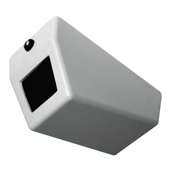
- Seite 1 LTC 9405 Series Wall/Ceiling Security Housings Philips Communication & Security Systems...
-
Seite 2: Important Safeguards
13. Power Lines - An outdoor system should not be located in the vicinity of overhead power lines or other electric light or power circuits, or where it IMPORTANT SAFEGUARDS can fall into such power lines or circuits. When installing an outdoor 1. -
Seite 3: Safety Precautions
SAFETY PRECAUTIONS CAUTION: TO REDUCE THE RISK OF ELECTRICAL SHOCK, DO NOT OPEN COVERS. NO USER SERVICEABLE PARTS INSIDE. REFER SERVICING TO QUALIFIED SERVICE PERSONNEL. This label may appear on the bottom of the unit due to space limitations. The lightning flash with an arrowhead symbol, within an equilateral triangle, is intended to alert the user to the presence of un-insulated "dangerous voltage"... -
Seite 5: Inhaltsverzeichnis
If the unit ever needs repair service, the customer should contact Models LTC 9405/01 and 9405/05 require the use of the the nearest Philips Communication & Security Systems Service key to unscrew the lock on the front of the cover. See Center for return authorization and shipping instructions. -
Seite 6: Installation
3. For all models, unscrew the screw or the lock until the front 2. Mark the anchor bolt locations on the mounting surface of the cover is free from the top panel. using the holes in the top panel as a template. At least four 8-mm (5/16-in.) anchor bolts will be needed. -
Seite 7: Final Assembly
Figure 9: Camera and Mount System Figure 6: Installing the Mount System Figure 10: Camera Mounted with Alternate Bracket to a Wall Final Assembly 1. Mount the cover by aligning the two studs near the rear of the cover with the openings of the z-shaped slots in the top panel. - Seite 8 2. Inspect the alignment of the camera / lens in the unit. The camera / lens should be placed as close to the viewing window as possible. Remove the cover and make adjustments as needed and then replace the cover. 3.
- Seite 9 SECURITE DANGER: POUR ÉVITER TOUT RISQUE D'ÉLECTROCUTION, NE PAS OUVRIR LE BOÎTIER. IL N'Y A PAS DE PIÈCES REMPLAÇABLES À L'INTÉRIEUR. POUR TOUTE RÉVISION, S'ADRESSER À UN TECHNICIEN SPÉCIALISÉ. En raison de limitation de place, cette étiquette peut être placée sur le dessous de l'appareil.
- Seite 11 électriques en vigueur transport, remettez-le dans son carton d'emballage et avertissez dans votre pays. le transporteur. Si l'un des éléments manque, contactez votre représentant ou votre service clientèle Philips Communication Outils requis : & Security Systems. Clé à vis 5/32".
-
Seite 12: Montage De L'unité
Panneau supérieur AVERTISSEMENT - N'utilisez pas le système de supports de fixation en forme de Z/pitons lorsque Insérez les pitons vous montez l'unité sur un mur. En effet, le capot (situés de chaque côté) pourrait se détacher du panneau supérieur. dans les supports de fixation en forme de Z 12-3/8 (14-3/8 min) - Seite 13 Surface de montage Veuillez vous référer à la figure 3 pour connaître Installation du bloc caméra/objectif l'espace minimum requis 1. Si dans le cadre d'une installation murale la caméra doit être Boulons montée horizontalement, retirez le support de fixation de la caméra du support de montage, puis installez l'applique de fixation amovible de la caméra fournie dans le kit matériel.
-
Seite 14: Montage Final
Remarque : Conservez l'outil spécial ou la clé. Vous pourriez en avoir besoin ultérieurement. Caméra 4. Lorsque l'unité est montée au plafond, vous ne devez ouvrir que la partie supérieure du capot pour entretenir et régler le bloc caméra/objectif. Pour ce faire, faites glisser le capot jusqu'à... -
Seite 15: Sicherheitsvorkehrungen
SICHERHEITSVORKEHRUNGEN VORSICHT: UM EINEN ELEKTRISCHEN SCHLAG ZU VERMEIDEN, ABDECKUNG NICHT ENTFERNEN. WARTUNGEN ALLER ART QUALIFIZIERTEM PERSONAL ÜBERLASSEN. Aus Platzgründen kann diese Warnung auf der Unterseite des Gerätes angebracht sein. Das Blitzsymbol im gleichseitigen Dreieck soll den Benutzer auf nicht isolierte "Hochspannung" im Gehäuse aufmerksam machen, die eventuell stark genug ist, um einen elektrischen Schlag zu verursachen. - Seite 17 Sie ihn entsprechend wieder in seinem Karton und Stärke erhältlich. informieren Sie den Spediteur. Sollte ein Posten fehlen, INSTALLATION informieren Sie Ihren Philips Communication & Security Systems Vertriebsverantwortlichen oder den Kundenservice. Die Installation sollte von qualifiziertem Service- Personal und gemäß anwendbarer lokaler Standards Der Versandkarton ist der sicherste Behälter, in dem das Gerät...
-
Seite 18: Montage Der Einheit
Befestigungsplatte WARNHINWEIS! - Verwenden Sie bei der Wandmontage keinesfalls die Schwenkvorrichtung. Die Abdeckung könnte ansonsten von der Befestigungsplatte fallen. lassen Sie die Bolzen in die Schlitze greifen (an beiden 12-3/8 14-3/8 min. Vorderseite Schwenkvorrichtung muß verwendet Seiten) werden Gehäuses Löcher für die Ankerschrauben (6) vor unbefugtem Verstellen gesicherte mindestens... -
Seite 19: Installation Der Kamera/Linse
Montageoberfläche. Siehe Abbildung 3 für den Mindestplatzbedarf. Installation der Kamera/Linse 1. Falls es erforderlich ist, die Kamera horizontal an der Wand Bolzen zu installieren, müssen die Kameraschienen der Installationsvorrichtung entfernt und gegen die im Zubehörset befindliche Kameraschiene ausgetauscht werden. Siehe Abbildung 5. Montageschiene Schraube Schraube... - Seite 20 4. Um Wartungs- oder Einstellarbeiten bei Kameras / Linsen in deckenmontierten Gehäusen vorzunehmen, reicht es, die Abdeckung lediglich abzuklappen. Die beiden Kamera Aufnahmebolzen auf der Rückseite der Abdeckung müssen dann in den z-förmigen Schlitzen der Befestigungsplatte verharren. WARNHINWEIS! - Verwenden Sie bei der Wandmontage keinesfalls die Schwenkvorrichtung.
-
Seite 21: Precauciones De Seguridad
PRECAUCIONES DE SEGURIDAD PRECAUCION: PARA REDUCIR EL RIESGO DE CHOQUE ELÉCTRICO, FAVOR NO ABRIR LA CUBIERTA. ESTE EQUIPO NO CONSTA DE PIEZAS O PARTES QUE REQUIEREN SERVICIO O MANTENIMIENTO. PARA REPARACIONES FAVOR REFERIRSE A UN TÉCNICO CALIFICADO. Debido a limitaciones de espacio, esta etiqueta puede aparecer en la parte inferior de la unidad. - Seite 23 En caso de que la unidad deba repararse, el cliente deberá La instalación debe llevarse a cabo por personal de ponerse en contacto con el Centro de servicios Philips servicio cualificado y cumplir el Código eléctrico Comunicaciones y Seguridad más cercano con el fin de obtener nacional (National Electrical Code) y los códigos locales...
-
Seite 24: Montaje De La Unidad
Panel superior ADVERTENCIA: - No utilice la característica de bisagras cuando monte la unidad en una pared. La tapa puede caerse del panel superior. Coloque los pasadores en las ranuras (ambos 12-3/8 (14-3/8 min. lados) Parte si se utiliza la características de frontal de bisagras) la carcasa... - Seite 25 Superficie de montaje Véase la figura 3 para ver el espacio mínimo necesario Instalación de cámara/lente 1. Si la instalación necesita que la cámara esté montada Pasadores horizontalmente en la pared, extraiga el soporte de la cámara del sistema de montaje e instale el soporte de cámara alternativo suministrado en el juego de hardware.
-
Seite 26: Montaje Final
ADVERTENCIA: - No utilice la característica de bisagras cuando monte la unidad en una pared, la tapa puede caerse del panel superior. Cámara Panel superior Soporte de cámara alternativo Figura 10: Cámara montada en una pared con el soporte alternativo Tapa en posición de abierto por las bisagras Montaje final... - Seite 27 VEILIGHEIDSVOORZORGEN VOORZICHTIG RISICO VAN ELEKTRISCHE SCHOK NIET OPENEN LET OP: OPEN DE BEHUIZING NIET OM HET RISICO OP EEN ELECTRISCHE SCHOK TE VOORKOMEN. HET APPARAAT BEVAT GEEN VERVANGBARE ONDERDELEN. LAAT ONDERHOUD OVER AAN GEKWALIFICEERD PERSONEEL. Dit label kan wegens ruimtegebrek op de onderkant van het apparaat zitten.
-
Seite 29: Onderhoud En Reparatie
Demonteren de expediteur. Ontbreken er onderdelen, neem dan contact op 1. Haal de eenheid uit de verpakking. met uw vertegenwoordiger van Philips CSS of met de servicedienst. 2. Voor de modellen LTC 9405/00 en 9405/03 is een speciaal gereedschap nodig om de beveiligingsschroef in het De doos is de veiligste verpakking voor elke vorm van transport. - Seite 30 Bovenpaneel WAARSCHUWING! Laat de behuizing nooit opengeklapt hangen als u de eenheid aan een wand ophangt, want dan kan het voorpaneel van het Zorg dat aan bovenpaneel vallen. weerszijden de steuntjes in de uitsparingen 12-3/8 (14-3/8 min.) vallen. Voorzijde Gebruik de scharnierverbinding behuizing Gaatjes voor bouten(6) Beveiligings-schroef...
- Seite 31 Montageoppervlak. Zie afb .3 voor minimaal vereiste ruimte. Camera/lens monteren 1. Als u de camera horizontaal aan een wand wilt monteren, Steunen maak de camera dan los van de montagebeugel en monteer de andere camerabeugel die als onderdeel van de kit is geleverd.
- Seite 32 4. Als de camera aan een plafond wordt opgehangen, dan kan het bovenpaneel worden geopend om onderhoud te plegen of de positie van de lens en de camera aan te passen. Zorg Camera dat de twee steunen bij de achterzijde van de kap in de Z- vormige uitsparingen in het bovenpaneel blijven rusten.
- Seite 33 NORME CAUTELATIVE DI SICUREZZA AVVERTENZA RISCHIO DI FOLGORAZIONE NON APRIRE! ATTENZIONE: PER RIDURRE IL RISCHIO DI SCOSSE ELETTRICHE, NON APRIRE I COPERCHI. ALL’INTERNO NON VI SONO COMPONENTI SU CUI L’UTENTE DEVE ESEGUIRE INTERVENTI DI MANUTENZIONE. AFFIDARE LA MANUTENZIONE A PERSONALE QUALIFICATO. A causa di limitazioni di spazio questa etichetta può...
-
Seite 35: Cura E Manutenzione
Se l'unità dovesse richiedere un intervento d'assistenza, il cliente uno strumento speciale per svitare la vite antiscasso situata è pregato di contattare il Centro assistenza Philips sulla parte frontale del coperchio. Vedi figura 1. Communication & Security Systems più vicino per ottenere il... -
Seite 36: Montaggio Dell'unità
Pannello superiore AVVERTENZA! - Non utilizzare i cardini quando l'unità è montata a parete. Il coperchio potrebbe scivolare fuori dal pannello superiore. Individvare le viti prigioniere nelle scanalature 12-3/8 (14-3/8 min. (entrambi i lati) se la caratteristica della cerniera deve essere usata Parte anteriore de... - Seite 37 Superficie di montaggio Vedi figura 3 per i requisiti di spazio minimi Installazione di telecamera/ottica 1. Se l'installazione richiede che la telecamera venga montata in Perni orizzontale sulla parete, rimuovere la staffa porta telecamera dal sistema di fissaggio ed installare la staffa alternativa fornita con il kit ferramenta.
-
Seite 38: Montaggio Finale
4. Per installazioni in cui l'unità viene montata a soffitto, il coperchio superiore può essere fissato in posizione aperta per le operazioni di regolazione o manutenzione del gruppo Telecamera telecamera / ottica. E' sufficiente fare in modo che i due perni posti sul retro del coperchio si inseriscano nella parte inferiore delle fessure a forma di z del pannello superiore. - Seite 40 3935 890 21181 99-40 © 1999 by Philips Electronics N.V. © 1999 by Philips Communication & Security Systems Inc. All Rights Reserved. Philips® is a registered trademark of Philips Electronics N. A. Corp. Data subject to change without notice...