Herunterladen Inhalt Inhalt Diese Seite drucken
Inhaltsverzeichnis

Werbung

Verfügbare Sprachen

Verfügbare Sprachen

deutsch
FU Basic
FU-BS
Helios Ventilatoren
Frequenzumrichter mit integriertem Sinuslter für 3 ~
Ventilatoren
Nr. 82935. 003/01.20
Montage- und Betriebsvorschrift
Drehzahlsteller mit 0...10 V Eingang zur Vorgabe der Ventilatordrehzahl
L-BAL-E187-D 2004 Index 003
Art.-Nr.

Werbung

Inhaltsverzeichnis
loading

Inhaltszusammenfassung für Helios FU Basic Serie

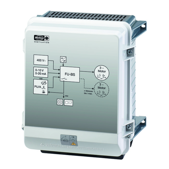
  • Seite 1 FU Basic FU-BS Helios Ventilatoren Frequenzumrichter mit integriertem Sinuslter für 3 ~ Ventilatoren Nr. 82935. 003/01.20 Montage- und Betriebsvorschrift Drehzahlsteller mit 0...10 V Eingang zur Vorgabe der Ventilatordrehzahl L-BAL-E187-D 2004 Index 003 Art.-Nr.
  • Seite 2: Inhaltsverzeichnis

    Montage- und Betriebsvorschrift FU Basic Inhaltsübersicht Allgemeine Hinweise ............Bedeutung der Betriebsanleitung .
  • Seite 3 Montage- und Betriebsvorschrift FU Basic 5.13 Potenzial der Steuerspannungsanschlüsse ....... . . Inbetriebnahme .
  • Seite 4: Allgemeine Hinweise

    Montage- und Betriebsvorschrift FU Basic Allgemeine Hinweise 1 Allgemeine Hinweise Die Einhaltung der nachfolgenden Vorgaben dient auch der Sicherheit des Produktes. Sollten die angegebenen Hinweise insbesondere zur generellen Sicherheit, Transport, Lagerung, Montage, Be- triebsbedingungen, Inbetriebnahme, Instandhaltung, Wartung, Reinigung und Entsorgung / Recycling nicht beachtet werden, kann das Produkt eventuell nicht sicher betrieben werden und kann eine Gefahr für Leib und Leben der Benutzer und dritter Personen darstellen.
  • Seite 5: Symbolerklärung

    Montage- und Betriebsvorschrift FU Basic Sicherheitshinweise Symbolerklärung Sicherheitshinweise werden durch ein Warndreieck hervorgehoben und je nach Gefährdungsgrad wie folgt dargestellt. Achtung! Allgemeine Gefahrenstelle. Tod, schwere Körperverletzung oder erheblicher Sachschaden können auftreten, wenn entsprechende Vorsichtsmaßnahmen nicht getroffen werden! Gefahr durch elektrischen Strom Gefahr durch gefährliche, elektrische Spannung! Tod oder schwere Körperverletzung können auftreten, wenn entsprechende Vorsichtsmaßnahmen nicht getroffen werden! Information...
  • Seite 6: Arbeiten Am Gerät

    Montage- und Betriebsvorschrift FU Basic Sicherheitshinweise Arbeiten am Gerät Information Montage, elektrischer Anschluss und Inbetriebnahme dürfen nur von einer Elektrofachkraft, entsprechend den elektrotechnischen Regeln (u. a. EN 50110 oder EN 60204) vorgenommen werden! Gefahr durch elektrischen Strom Es ist grundsätzlich verboten, Arbeiten an Geräteteilen durchzuführen, die unter Spannung •...
  • Seite 7: Beschäftigung Von Betriebsfremdem Personal

    Montage- und Betriebsvorschrift FU Basic Produktübersicht Alle am Gerät angebrachten Sicherheits- und Warnhinweise dürfen nicht entfernt werden und • müssen leserlich bleiben. Beschäftigung von betriebsfremdem Personal Instandhaltungs- und Wartungsarbeiten werden häufig von betriebsfremdem Personal durchgeführt, dass die speziellen Umstände und die daraus resultierenden Gefahren oft nicht kennt. Diese Perso- nen müssen ausführlich über die Gefahren in ihrem Tätigkeitsbereich informiert werden.
  • Seite 8: Mindestplatzbedarf

    Montage- und Betriebsvorschrift FU Basic Montage Vor der Montage Gerät aus Verpackung nehmen und auf eventuelle Transportschäden über- • prüfen. Bei einem vorliegenden Transportschaden ist die Inbetriebnahme nicht zulässig! • Bei einem Gewicht größer 25 kg bei Männern / 10 kg bei Frauen, ist das Herausnehmen des Gerätes mit zwei Personen durchzuführen (nach REFA).
  • Seite 9: Elektrische Installation

    Montage- und Betriebsvorschrift FU Basic Elektrische Installation 5 Elektrische Installation Sicherheitsvorkehrungen Gefahr durch elektrischen Strom Arbeiten an elektrischen Teilen dürfen nur von einer Elektrofachkraft oder elektrisch • unterwiesenen Personen unter Aufsicht einer Elektrofachkraft gemäß den Regeln der Technik durchgeführt werden. Die 5 elektrischen Sicherheitsregeln müssen beachtet werden! •...
  • Seite 10: Netzanschluss

    Montage- und Betriebsvorschrift FU Basic Elektrische Installation Netzanschluss 5.3.1 Netzspannung Der Netzanschluss erfolgt an den Klemmen: PE, L1, L2, L3. Dabei ist unbedingt darauf zu achten, dass die Netzspannung innerhalb der zulässigen Toleranzangaben liegt ( Technische Daten und seitlich angebrachtes Typenschild). Gefahr durch elektrischen Strom Nicht für IT-System geeignet! Nicht an geerdetem Dreieck-System betreiben!
  • Seite 11: U/F Kennlinie

    Montage- und Betriebsvorschrift FU Basic Elektrische Installation 5.5.3 U/f Kennlinie Diagramm Vorgabesignal und U/f Kennlinie (quadratisch) = 50 Hz 100 % = 48.5 Hz edge = 0 % [Hz] start Analog In 1 0...10 V 0...20 mA 90 100 0...100 % PWM 01.02.2013 v_u_f_fcon_basic_setsig.vsd Analog In: Drehzahlvorgabesignal (0 - 10 V, 0...20 mA, 0...100 % PWM)
  • Seite 12: Analog Eingang "E1" Zur Vorgabe Der Ventilatordrehzahl

    Montage- und Betriebsvorschrift FU Basic Elektrische Installation Analog Eingang “E1” zur Vorgabe der Ventilatordrehzahl Das Gerät besitzt einen analog Eingang zur Vorgabe der Ventilatordrehzahl. Anschluss “E1” / “GND” (Analog In 1). Werkseitig sind die internen Stecker “E1.1” und “E1.2” in der Position für ein 0...10 V Drehzahlvor- gabesignal.
  • Seite 13: Ausgangsspannung "10 V

    Montage- und Betriebsvorschrift FU Basic Elektrische Installation 0...100 % PWM Ansteuerung über externes Vorgabesignal PWM D1 GND 10V D1 GND 10V 24V (10 V) E1,1 E1,2 E1,1 E1,2 10 k f = 1...10 kHz 31.01.12 i_jumper_if_basic_pwm.eps 15...28 V Gefahr durch elektrischen Strom •...
  • Seite 14: Bypass-Schaltung

    Montage- und Betriebsvorschrift FU Basic Inbetriebnahme 5.12 Bypass-Schaltung Bei einer Bypass-Schaltung (Reglerumgehung mit Netzspannung) ist zu beachten: • Gegenseitige Verriegelung von Netzschütz und Bypass-Schütz. Zeitverzögerung bei Umschaltung mindestens 1 Sekunde. • Mit Abschalten des Schützes am Umrichterausgang muss die “Freigabe” (ON / OFF) mit •...
  • Seite 15: Diagnose / Störungen

    Montage- und Betriebsvorschrift FU Basic Diagnose / Störungen 7 Diagnose / Störungen Über die Status LED werden die Betriebszustände über einen Blinkcode signalisiert. 10 x 11 x 12 x 13 x 14 x 15 x 16 x 17 x 10.01.2014 v_flash_explain_1_17.vsd Relais Reaktion des Gerätes...
  • Seite 16 Montage- und Betriebsvorschrift FU Basic Diagnose / Störungen Relais Reaktion des Gerätes Code Erklärung Behebung ZK Unterspannung Die Modulation wird bei Unterspannung sofort abgeschaltet, Fehlermeldung Zwischenkreisspannung länger als 75 s nach 75 s. unter festgelegtem Grenzwert. Automatische Wiedereinschaltung und abgefallen, 13 - 14 Abschaltung der Fehlermeldung, wenn unterbrochen die Spannung für mindestens 5 s über...
  • Seite 17: Anhang

    Montage- und Betriebsvorschrift FU Basic Anhang Relais Reaktion des Gerätes Code Erklärung Behebung Überlastfehler Nach 4maligem Erkennen (I t-Verfahren; maximale Überlast liegt über 60s an) Der Umrichter wurde über die Strombe- wird der Fehler gesetzt. grenzung abgeschaltet. Nach jedem Erkennen (IGTB Recovery Flag wird gesetzt) wird 30 s abgewartet, bis ein erneuter Versuch gestartet wird.
  • Seite 18 Montage- und Betriebsvorschrift FU Basic Anhang Eingangswiderstand Drehzahlvorga- 0...10 V Eingang: R = 300 kΩ besignal 0...20 mA Eingang: R = 500 Ω PWM-Eingang U 14...28 V: @ 14 V = 21,6 kΩ @ 28 V = 3,6 kΩ Digital Eingang “D1” Eingangswiderstand: R ca.
  • Seite 19: Max. Belastung Abhängig Von Umgebungstemperatur Und Netzspannung

    Montage- und Betriebsvorschrift FU Basic Anhang 8.1.1 Max. Belastung abhängig von Umgebungstemperatur und Netzspannung Die höchst zulässige Temperatur für den Bemessungsstrom bei Bemessungsspannung wird als Bemessungstemperatur angegeben. Da die Abfuhr der im Gerät entstehenden Verlustleistung (Wärmeentwicklung) entscheidend von der Umgebungstemperatur abhängig ist, muss bei einer Umgebungstemperatur über der Bemessungs- temperatur, die max.
  • Seite 20: Anschlussplan

    Montage- und Betriebsvorschrift FU Basic Anhang Anschlussplan 8.2.1 Anschlussplan Standard 0(4)-20 mA Relais FU-BS Betriebsmeldung TP=Kaltleiter 0-100% PWM 250V/2A TB=Thermo- 0-10 V kontakt 13 14 L1 L2 L3 U V W Motor oder 3~ 400 V bei den Typen 10 / 14 A 10mm²...
  • Seite 21: Maßblatt [Mm]

    Montage- und Betriebsvorschrift FU Basic Anhang Maßblatt [mm] FU-BS 2.5 FU-BS 5, 8, 10, 16 L-BAL-E187-D 2004 Index 003 Art.-Nr. 21/22...
  • Seite 22: Service Und Information

    Montage- und Betriebsvorschrift FU Basic Anhang Service und Information Helios Ventilatoren GmbH + Co KG • Lupfenstraße 8 • 78056 Villingen-Schwenningen Helios Ventilateurs • Le Carré des Aviateurs • 157 av. Charles Floquet • 93155 Le Blanc Mesnil Cedex Helios Ventilatoren AG •...
  • Seite 23 FU Basic FU-BS Helios fans Frequency inverter with integrated sine lter for 3 ~ fans No. 82935. 003/01.20 Installation and Operating Specication Speed controller with 0...10 V input for presetting the fan speed L-BAL-E187-GB 2004 Index 003 Part.-No.
  • Seite 24 Installation and Operating Specification FU Basic Content General notes ............. Structure of the operating instructions .
  • Seite 25 Installation and Operating Specification FU Basic 5.13 Potential at control voltage connections ........Start-up .
  • Seite 26: General Notes

    Installation and Operating Specification FU Basic General notes 1 General notes Compliance with the following instructions is mandatory to ensure the functionality and safety of the product. If the following instructions given especially but not limited for general safety, transport, storage, mounting, operating conditions, start-up, maintenance, repair, cleaning and disposal / recy- cling are not observed, the product may not operate safely and may cause a hazard to the life and limb of users and third parties.
  • Seite 27: Explanations Of Symbols

    Installation and Operating Specification FU Basic Safety instructions Explanations of symbols Safety instructions are highlighted with warning triangles and are depicted according to the degree of hazard as follows. Attention! General hazardous area. Death or severe injury or significant property damage can occur if the corresponding precautions are not taken! Danger due to electric current Danger by dangerous, electric voltage! Death or severe injury can occur if the corresponding...
  • Seite 28: Work On The Device

    Installation and Operating Specification FU Basic Safety instructions Work on the device Information Mounting, electrical connection, and start-up operation may only be carried out by an electrical specialist in accordance with electrotechnical regulations (e.g. EN 50110 or EN 60204)! Danger due to electric current It is generally forbidden to carry out work on electrical live parts.
  • Seite 29: Employment Of External Personnel

    Installation and Operating Specification FU Basic Product overview Employment of external personnel Maintenance and service work are frequently carried out by external employees who often do not recognize the specific situations and the thus resulting dangers.These persons must be comprehen- sively informed about the hazards in their area of activity.
  • Seite 30: Minimum Space Requirement

    Installation and Operating Specification FU Basic Mounting • Before installation remove the device from the packing and check for any possible shipping damage! Start-up is not allowed in the case of transport damage! At a weight greater than 25 kg for men / 10 kg for women, the fan should be lifted out by two •...
  • Seite 31: Electrical Installation

    Installation and Operating Specification FU Basic Electrical installation 5 Electrical installation Safety precautions Danger due to electric current Work on electric components may only be carried out by trained electricians or by persons • instructed in electricity under the supervision of an electrician in accordance with electrical engineering regulations.
  • Seite 32: Mains Connection

    Installation and Operating Specification FU Basic Electrical installation Mains connection 5.3.1 Line voltage Power from the mains is connected to terminals: PE, L1, L2, L3. Here, it must be strictly observed that the mains voltage lies within the allowable tolerance specifications ( Technical data and nameplate affixed to the side).
  • Seite 33: U/F-Characteristic Curve

    Installation and Operating Specification FU Basic Electrical installation 5.5.3 U/f-characteristic curve Diagram setting signal and U/f curve (quadratic) = 50 Hz 100 % = 48.5 Hz edge = 0 % [Hz] start Analog In 1 0...10 V 0...20 mA 90 100 0...100 % PWM 01.02.2013 v_u_f_fcon_basic_setsig.vsd Analog In: Speed setting signal (0 - 10 V, 0...20 mA, 0...100 % PWM)
  • Seite 34: Analog Input "E1" For Setting Fan Speed

    Installation and Operating Specification FU Basic Electrical installation Analog input “E1” for setting fan speed The device has an analog input for setting the fan speed. Connection “E1” / “GND” (Analog In 1). The internal jumpers “E1.1” and “E1.2” are factory set in the position for a 0...10 V speed setting signal.
  • Seite 35: Output Voltage "10 V

    Installation and Operating Specification FU Basic Electrical installation 0...100 % PWM Control via external setting signal PWM D1 GND 10V D1 GND 10V 24V (10 V) E1,1 E1,2 E1,1 E1,2 10 k f = 1...10 kHz 31.01.12 i_jumper_if_basic_pwm.eps 15...28 V Danger due to electric current Do not replug the jumper under voltage, observe the safety instructions! •...
  • Seite 36: Bypass Circuit

    Installation and Operating Specification FU Basic Start-up 5.12 Bypass circuit Please observe the following during bypass switching (controller shunt with mains voltage): • Mutual locking of mains contactor and bypass protection. Time delay of at least 1 second during switching. •...
  • Seite 37: Diagnostics / Faults

    Installation and Operating Specification FU Basic Diagnostics / Faults 7 Diagnostics / Faults Operating conditions are indicated by the status LED with flashing code. 10 x 11 x 12 x 13 x 14 x 15 x 16 x 17 x 10.01.2014 v_flash_explain_1_17.vsd Reaction of device...
  • Seite 38 Installation and Operating Specification FU Basic Diagnostics / Faults Reaction of device Relay Code Explanation Adjustment Intermediate undervoltage The modulation is switched off immedi- ately at undervoltage, error message Intermediate circuit voltage below a fixed after 75 s. limit for longer than 75 s. Automatic switching back on and switch- de-energized, 13 - ing off of error message when the volt-...
  • Seite 39: Enclosure

    Installation and Operating Specification FU Basic Enclosure Reaction of device Relay Code Explanation Adjustment Overload fault The error is set after detecting 4 times t-process; maximum overload applied The controller was switched off by the for 60 s). current limitation. After every detection (IGTB Recovery Flag is set) there is a 30 s wait until a new attempt is started.
  • Seite 40 Installation and Operating Specification FU Basic Enclosure Digital input “D1” Input resistance: R approx. 4 kΩ Voltage range high level: 10..30 V DC Voltage range low level: 0..4 V DC Voltage supply for external devices +24 V ± 20 %, I 70 mA Power loss in standby approx.
  • Seite 41: Max. Load Dependent On Ambient Temperature And Line Voltage

    Installation and Operating Specification FU Basic Enclosure 8.1.1 Max. load dependent on ambient temperature and line voltage. The maximum permissible temperature for the rated current at rated voltage is specified as rated temperature. Since the dissipation of the power loss (heat development) in the device is decisively dependent on the ambient temperature, the max.
  • Seite 42: Connection Diagram

    Installation and Operating Specification FU Basic Enclosure Connection diagram 8.2.1 connection diagram Standard 0(4)-20 mA Relais FU-BS Betriebsmeldung TP=Kaltleiter 0-100% PWM 250V/2A TB=Thermo- 0-10 V kontakt L1 L2 L3 U V W 13 14 Motor oder 3~ 400 V bei den Typen 10 / 14 A 10mm²...
  • Seite 43: Dimensions [Mm]

    Installation and Operating Specification FU Basic Enclosure Dimensions [mm] FU-BS 2.5 FU-BS 5, 8, 10, 16 L-BAL-E187-GB 2004 Index 003 Part.-No. 21/22...
  • Seite 44: Service And Information

    Installation and Operating Specification FU Basic Enclosure Service and Information Helios Ventilatoren GmbH + Co KG • Lupfenstraße 8 • 78056 Villingen-Schwenningen Helios Ventilateurs • Le Carré des Aviateurs • 157 av. Charles Floquet • 93155 Le Blanc Mesnil Cedex Helios Ventilatoren AG •...
  • Seite 45 FU Basic FU-BS Ventilateurs Helios Convertisseur de fréquence avec ltre sinus intégré pour ventilateurs 3 ~ n° 82935. 003/01.20 Prescription de montage et d’utilisation Régulateur de vitesse avec entrée 0...10 V pour la spécification de la vitesse du ventilateur L-BAL-E187-F 2004 Index 003 Art.N°.
  • Seite 46 Prescription de montage et d’utilisation FU Basic Sommaire Instructions générales ............Importance de la notice d’utilisation .
  • Seite 47 Prescription de montage et d’utilisation FU Basic 5.12 Câblage de dérivation ..........5.13 Potentiel des raccordements de tension de commande .
  • Seite 48: Instructions Générales

    Prescription de montage et d’utilisation FU Basic Instructions générales 1 Instructions générales Le respect des consignes suivantes vise également à assurer la sécurité du produit. Si les consignes de sécurité en général, de transport, de stockage, de montage, d'utilisation, de mise en service, de maintenance, d'entretien, de nettoyage et d'élimination/recyclage ne sont pas respectées, le produit ne pourra éventuellement pas être utilisé...
  • Seite 49: Explication Des Symboles

    Prescription de montage et d’utilisation FU Basic Consignes de sécurité Explication des symboles Les consignes de sécurité sont mises en évidence par un triangle d’avertissement et représentées selon le degré de dangerosité comme suit. Précaution ! Zone de danger générale. Mort, graves blessures corporelles ou dommages importants aux biens peuvent survenir lorsque les mesures de précaution ne sont pas prises ! Danger présenté...
  • Seite 50: Travaux Sur L'appareil

    Prescription de montage et d’utilisation FU Basic Consignes de sécurité Travaux sur l’appareil Information Le montage, le raccordement électrique et la mise en service ne doivent être effectués que par un électricien dans le respect des règlements électrotechniques (entre autres EN 50110 ou EN 60204) ! Danger présenté...
  • Seite 51: Emploi De Personnel Ne Faisant Pas Partie De L'entreprise

    Prescription de montage et d’utilisation FU Basic Aperçu des produits Le personnel doit être régulièrement informé de toutes les questions en matière de sécurité au • travail et de protection de l'environnement et doit connaître la notice d'assemblage et/ou notice d'utilisation et en particulier les consignes de sécurité...
  • Seite 52: Montage

    Prescription de montage et d’utilisation FU Basic Montage 4 Montage Instructions générales Précaution ! Pour éviter un défaut de l’appareil causé par un montage défectueux ou des influences de l'environnement, il convient de respecter les points sous-mentionnés pendant l'installation mécanique •...
  • Seite 53: Montage À L'extérieur

    Prescription de montage et d’utilisation FU Basic Installation électrique Montage à l’extérieur Un montage à l’extérieur est possible jusqu’à -20 °C si l’appareil n’est pas mis hors circuit. Dans la mesure du possible, installation protégée des intempéries, c.-à-d. exclure le rayonnement solaire direct ! Emplacement d’installation en agriculture Si vous utilisez l'appareil pour l'élevage, dans la mesure du possible ne pas monter celui-ci directe-...
  • Seite 54: Installation Cem Conforme

    Prescription de montage et d’utilisation FU Basic Installation électrique Installation CEM conforme 5.2.1 Câble moteur La norme applicable pour les émissions parasites est la EN 61000-6-3. Le respect de la norme est obtenu avec un câble d’alimentation moteur non blindé. 5.2.2 Câbles de commande Pour éviter les interférences, il convient de respecter un dégagement suffisant par rapport aux câbles...
  • Seite 55: Sortie De Convertisseur De Fréquence

    Prescription de montage et d’utilisation FU Basic Installation électrique Sortie de convertisseur de fréquence 5.5.1 Raccordement moteur Le raccordement moteur est réalisé aux bornes : PE, U, V, W. Plusieurs moteurs peuvent être raccordés à l'appareil. Cependant, la somme des courants de régulation max. de tous les moteurs ne doit pas dépasser le courant de mesure de l’appareil.
  • Seite 56: U/F-Courbe Caractéristique

    Prescription de montage et d’utilisation FU Basic Installation électrique 5.5.3 U/f-courbe caractéristique Diagramme Signal de consigne et U/f-courbe caractéristique (Quadratique) = 50 Hz 100 % = 48.5 Hz edge = 0 % [Hz] start Analog In 1 0...10 V 0...20 mA 90 100 0...100 % PWM 01.02.2013 v_u_f_fcon_basic_setsig.vsd...
  • Seite 57: Entrée Analogique "E1" Pour Déterminer La Vitesse Du Ventilateur

    Prescription de montage et d’utilisation FU Basic Installation électrique Entrée analogique “E1” pour déterminer la vitesse du ventilateur L’appareil dispose d’une entrée analogique permettant de spécifier la vitesse du ventilateur. Raccor- dement “E1” / “GND” (Analog In 1). Les connecteurs internes “E1.1” et “E1.2” sont positionnés d’origine pour un signal de consigne de vitesse de 0...10 V.
  • Seite 58: Tension De Sortie "10 V

    Prescription de montage et d’utilisation FU Basic Installation électrique 0...100 % PWM Commande via un signal de consigne externe PWM D1 GND 10V D1 GND 10V 24V (10 V) E1,1 E1,2 E1,1 E1,2 10 k f = 1...10 kHz 31.01.12 i_jumper_if_basic_pwm.eps 15...28 V Danger présenté...
  • Seite 59: Câblage De Dérivation

    Prescription de montage et d’utilisation FU Basic Mise en service 5.12 Câblage de dérivation Pour un câblage de dérivation (contournement du régulateur avec la tension du réseau), il convient de respecter ce qui suit : Interverrouillage du contacteur réseau et du contacteur de dérivation. •...
  • Seite 60: Diagnostic / Dérangements

    Prescription de montage et d’utilisation FU Basic Diagnostic / Dérangements 7 Diagnostic / Dérangements La LED d’état indique les états de fonctionnement par un code clignotant. 10 x 11 x 12 x 13 x 14 x 15 x 16 x 17 x 10.01.2014 v_flash_explain_1_17.vsd...
  • Seite 61 Prescription de montage et d’utilisation FU Basic Diagnostic / Dérangements Réaction de l’appareil Relais Code Explication Elimination Défaut IGBT L’appareil s’arrête, nouvelle tentative de démarrage après env. 60 s Code 9. Court-circuit à la terre ou court-circuit en sortie du convertisseur. Arrêt définitif si un défaut est de nouveau retombé, 13 - 14 in- détecté...
  • Seite 62: Annexe

    Prescription de montage et d’utilisation FU Basic Annexe Réaction de l’appareil Relais Code Explication Elimination Défaut moteur L’appareil s’arrête et ne redémarre pas. Déclenchement d’un interrupteur ther- Contrôle du moteur et du raccordement mostatique raccordé ou d’un capteur de puis Reset ( protection du moteur).
  • Seite 63 Prescription de montage et d’utilisation FU Basic Annexe Tension du réseau* 3 ~ 208...480 V (-15 à +10 %), 50/60 Hz Tension nominale 400 V Tension de sortie maximale env. 95 % de U réseau Fréquence de sortie maximale 50 Hz Edgefrequency 48.5 Hz U/f-courbe caractéristique...
  • Seite 64: Charge Max. En Fonction De La Température Ambiante Et De La Tension Du Réseau

    Prescription de montage et d’utilisation FU Basic Annexe Bruit de large bande (essai de durée de vie simulé) selon EN 61373, Résistance aux vibrations catégorie 1, classe B. (pour montage vertical, c.-à-d. intro- Essai de chocs selon EN 61373, catégorie 1 duction des câbles par le bas).
  • Seite 65: Schéma De Raccordement

    Prescription de montage et d’utilisation FU Basic Annexe Schéma de raccordement 8.2.1 Schéma de raccordement Standard 0(4)-20 mA Relais FU-BS Betriebsmeldung TP=Kaltleiter 0-100% PWM 250V/2A TB=Thermo- 0-10 V kontakt L1 L2 L3 U V W 13 14 Motor oder 3~ 400 V bei den Typen 10 / 14 A 10mm²...
  • Seite 66: Dimensions [Mm]

    Prescription de montage et d’utilisation FU Basic Annexe Dimensions [mm] FU-BS 2.5 FU-BS 5, 8, 10, 16 L-BAL-E187-F 2004 Index 003 Art.N°. 22/23...
  • Seite 67: Service Et Information

    Prescription de montage et d’utilisation FU Basic Annexe Service et information Helios Ventilatoren GmbH + Co KG • Lupfenstraße 8 • 78056 Villingen-Schwenningen Helios Ventilateurs • Le Carré des Aviateurs • 157 av. Charles Floquet • 93155 Le Blanc Mesnil Cedex Helios Ventilatoren AG •...

Diese Anleitung auch für:

Fu-bs 2,5Fu-bs 5,0Fu-bs 8,0Fu-bs 10Fu-bs 16

Inhaltsverzeichnis