Phoenix Contact EM-PB-GATEWAY-IFS Handbuch
Inhaltsverzeichnis
Verfügbare Sprachen
Verfügbare Sprachen
Quicklinks
PHOENIX CONTACT GmbH & Co. KG
D-32823 Blomberg, Germany
Fax +49-(0)5235-341200 Phone +49-(0)5235-300
www.phoenixcontact.com
PHOENIX CONTACT GmbH & Co. KG
D-32823 Blomberg, Germany
Fax +49-(0)5235-341200, Phone +49-(0)5235-300
www.phoenixcontact.com
PROFIBUS-Ankoppler für INTERFACE-Systemgeräte
DE
PROFIBUS coupler for INTERFACE system devices
EN
Coupleur PROFIBUS pour appareils système INTERFACE
FR
Acoplador PROFIBUS para aparatos del sistema INTERFACE
ES
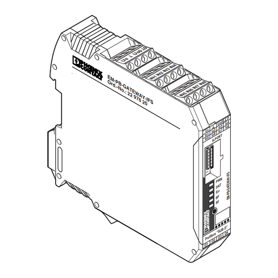
EM-PB-GATEWAY-IFS
E M
O r
© PHOENIX CONTACT 2009
MNR 9039888 / 04.2009
Art.-Nr.: 2297620
- P B
d . -
- G
N o
A T
. : 2
E W
2 9
A Y
7 6
- I F
2 0
S
O
O
In 4
U
S
In 3
In 8
In 2
In 7
U
S
In 1
In 6
T
O R
In 5
S - P
R
P W
T
D A
E r r
B F
S F
"
B D
" S U
O 4
u s
f ib
O 3
P r o
O 2
O 1
Inhaltsverzeichnis

Verwandte Anleitungen für Phoenix Contact EM-PB-GATEWAY-IFS

Inhaltszusammenfassung für Phoenix Contact EM-PB-GATEWAY-IFS
- Seite 1 PHOENIX CONTACT GmbH & Co. KG D-32823 Blomberg, Germany Fax +49-(0)5235-341200, Phone +49-(0)5235-300 www.phoenixcontact.com MNR 9039888 / 04.2009 PROFIBUS-Ankoppler für INTERFACE-Systemgeräte PROFIBUS coupler for INTERFACE system devices Coupleur PROFIBUS pour appareils système INTERFACE Acoplador PROFIBUS para aparatos del sistema INTERFACE EM-PB-GATEWAY-IFS Art.-Nr.: 2297620...
-
Seite 2: Inhaltsverzeichnis
Inhaltsverzeichnis Seite Sommaire Page 1. Kurzbeschreibung..................5 1. Brève description ..................41 2. Begriffsdefinitionen ..................5 2. Définitions des termes ................41 3. Anschlusshinweise ..................6 3. Conseils de raccordement ...............42 4. Funktion 4. Fonction 4.1. Status-LEDs ......................7 4.1. LED d'état .....................43 4.2. Handhabung S-PORT ..................7 4.2. -
Seite 3: Kurzbeschreibung
DEUTSCH 1. Kurzbeschreibung Die Baugruppe EM-PB-GATEWAY-IFS dient der Ankopplung von Geräten der Interface-System-Familie PROFIBUS-Ankoppler für INTERFACE-Systemgeräte an den PROFIBUS-DP gemäß EN 50170. Es können bis zu 32 Geräte (Slaves) angeschlossen werden. Das Gateway kann von jedem normkonformen C0-Master im zyklischen Datenaustausch betrieben wer- z.B. -
Seite 4: Anschlusshinweise
Prozessfehler oder Fehler in der Peripherie eines Teilnehmers blinkend 2,8 Hz (schnell) PROFIBUS-Konfiguration und Stationsaufbau stimmen nicht überein Abb. 3 4.2. Handhabung S-PORT Das EM-PB-GATEWAY-IFS unterstützt sowohl aktive Erweiterungen wie den USB-Programmier-Adap- ter IFS-USB-PROG-ADAPTER (Art.-Nr.: 2811271), als auch einen optionalen "Speicherstick" IFS- CONFSTICK. -
Seite 5: Betriebsart Parametrierung - Einstellen Der Profibus-Adresse
Null zurückgesetzt. • Zum Beenden der Slave-Adressvergabe betätigen • Zum Speichern der Einstellung und Übernehmen der Sie den Taster am EM-PB-GATEWAY-IFS ein zwei- neuen Adresse betätigen Sie den Taster ein zweites tes Mal länger als 12 Sekunden (12 s). Mal länger als sechs Sekunden (6 s). -
Seite 6: Aufbau Des Parametrierungstelegrammes
5.1. Aufbau des Parametrierungstelegrammes auf Anforderung des PROFIBUS-Masters. Bei jedem Anlauf des EM-PB-GATEWAY-IFS am PROFIBUS-DP werden an das Gerät Parameter über- Das System unterscheidet zwischen Status- und Fehlermeldungen. Fehlermeldungen sind mit E gekenn- tragen. Abhängig von der verwendeten Masterbaugruppe werden dabei Normparameter, oder Normpa- zeichnet und werden mit hoher Priorität an den Master gesendet. - Seite 7 Byte Bemerkung Byte Bemerkung IFSM Slave Error 2 (Modul fehlerhaft bzw. Gerät nicht vorhanden) Slave 19: process or peripherie error Slave 16: error or missing Slave 18: process or peripherie error Slave 15: error or missing Slave 17: process or peripherie error Slave 14: error or missing IFSM Device Process, Peripherie 4 Slave 13: error or missing...
-
Seite 8: Konfigurationstelegramm
6.2. Modulstatus Der Modulstatus bildet den internen Status des Gateways ab. Er liefert die gleichen Informationen, wie Das EM-PB-GATEWAY-IFS realisiert einen modularen Slave. Abhängig von der Konfiguration unter- sie auch im Diagnosetelegramm zu finden sind. scheidet er die Betriebsarten "automatische IFSM-Konfiguration" und "Konfiguration via DTM". - Seite 9 6.4. EMM-Objekte Beschreibung Slave Error State 2 ELR/EMM Control (Device:1) ... ELR/EMM Control (Device:8) Teilnehmer 17: fehlerhaft, nicht vorhanden, schwerwiegender interner Fehler Teilnehmer 18: fehlerhaft, nicht vorhanden, schwerwiegender interner Fehler Beschreibung ELR/EMM Control Teilnehmer 19: fehlerhaft, nicht vorhanden, schwerwiegender interner Fehler 15...8 Status der Informationen der digitalen Ausgänge (O8 ...
- Seite 10 Beschreibung ELR/EMM Module State 2 Beschreibung ELR/EMM Channel State 3 Fehlerquittierung fehlerhaft Unterbrechung Motorleitung T1 Reserviert Unterbrechung Motorleitung T2 Reserviert Unterbrechung Motorleitung T3 Reserviert Wirkleistungs-Überschreitung Reserviert Wirkleistungs-Unterschreitung Reserviert Wirkleistungs-Überschreitung (Meldeschwelle) Reserviert Wirkleistungs-Unterschreitung (Meldeschwelle) Testbetrieb Antriebskontrolle: Automatik / Manuell Antriebskontrolle: Inbetriebnahme-Tool 4 Hz-Takt: das Signal wird alle 0,2 s invertiert Antriebskontrolle: LOKAL 1 10 Hz-Takt: das Signal wird alle 50 ms invertiert...
- Seite 11 Die Darstellung eines Analogwertes erfolgt in einem 16 Bit-Datenwort im Zweierkomplement (integer 16). Artikel-Nr. EM-PB-GATEWAY-IFS 2297620 Neben dem Fehlercode 8040h, der vom EM-PB-GATEWAY-IFS generiert wird, wenn keine Kommunika- Versorgung tion mit dem zugeordneten Slaves möglich ist, sind noch weitere Fehlercodes definiert. Sie beziehen sich Betriebsspannung U 24 V DC auf den Status des Messwertes, nicht auf den Zustand des angeschlossen Teilnehmers.