
Verwandte Anleitungen für Videotec TWRB series

Inhaltszusammenfassung für Videotec TWRB series
- Seite 1 MANUALE D’USO __________________________ OPERATING INSTRUCTIONS __________________________ MANUEL D’INSTRUCTIONS __________________________ BEDIENUNGSANWEISUNG...
- Seite 2 MANUALE D’USO...
-
Seite 3: Inhaltsverzeichnis
INDICE INDICE ....................................1 INTRODUZIONE ..................................2 Contenuto dell’imballo ....................................2 Cosa contiene questo manuale ................................. 2 Convenzioni tipografiche ................................... 2 NORME DI SICUREZZA.................................2 DATI DI MARCATURA ................................3 DESCRIZIONE DEL RICEVITORE TWRB/TWRR.........................3 Caratteristiche ......................................3 INSTALLAZIONE ..................................3 Apertura dell’imballaggio ................................... 3 Controllo della marcatura ..................................3 CONFIGURAZIONE DEL RICEVITORE TWRB/TWRR......................4 Trimmers, dip-switches e jumper per la configurazione .......................... -
Seite 4: Introduzione
Introduzione Contenuto dell’imballo • 1 ricevitore TWRB/TWRR • 1 manuale d’uso Alla consegna del prodotto verificare che l’imballo sia integro e non abbia segni evidenti di cadute o abrasioni. In caso di evidenti segni di danno all’imballo contattare immediatamente il fornitore. Controllare che il contenuto sia rispondente alla lista del materiale sopra indicata. -
Seite 5: Dati Di Marcatura
Dati di marcatura Sul ricevitore TWRB/TWRR sono riportate due etichette conformi alla marcatura CE. La prima etichetta contiene: • Codice di identificazione del modello (Codice a barre Extended 3/9 ) • Tensione di alimentazione (Volt) • Frequenza (Hertz) • Consumo (Watt) La seconda etichetta indica il numero di serie del modello (codice a barre Extended 3/9) All’atto dell’installazione controllare se le caratteristiche di alimentazione del ricevitore corrispondono a quelle richieste. -
Seite 6: Configurazione Del Ricevitore Twrb/Twrr
Configurazione del ricevitore TWRB/TWRR Trimmers, dip-switches e jumper per la configurazione Nella figura seguente sono indicati i trimmers, i dip-switchs e il jumper per la configurazione : Regolazione fine LF-III Regolazione fine HF-III Alimentazione AC / DC Indicatore di livello sul segnale video MF-III regolazione fine Indicatore per l’alimentazione Uscita... -
Seite 7: Regolazione Dell'impedenza Di Ingresso
6. Posizionare lo switch 16 di SW2 in posizione ON 7. Regolare i trimmers TC1,TC2,TC3,TC4 sui valori minimi di capacità Regolazione dell’impedenza di ingresso L’impedenza di ingresso deve assumere valori diversi a seconda del tipo di cavo utilizzato per la trasmissione del segnale video dall’unità... -
Seite 8: Collegamenti
Collegamenti Esempio di installazione Il segnale video della telecamera in ingresso al trasmettitore TWT viene visualizzato sul monitor collegato in uscita al ricevitore TWRB/TWRR; il segnale video è trasmesso attraverso un cavo bifilare : MATERIALE IMPIEGATO TWRB/TWRR Parte video: • 1 monitor •... -
Seite 9: Tipo Di Cavo
Tipo di cavo Il tipo di cavo da utilizzare è un cavo di UTP (Unshielded Twisted Pair) Cat. 5 (definito secondo gli standard TIA/EIA 568A e ISO/IEC 11801). Con questo cavo si possono coprire lunghe distanze ed è possibile far passare più segnali video (max.4) o di telemetria nello stesso cavo. -
Seite 10: Manutenzione
Manutenzione Il ricevitore TWRB/TWRR non necessita di particolare manutenzione. Si raccomanda di utilizzarlo poggiato su una base solida, con i cavi di alimentazione e di collegamento in posizione tale da non essere causa di intralcio all’operatore. Risoluzione di problemi Il ricevitore TWRB/TWRR è caratterizzato da una notevole facilità d’uso, ma ciononostante possono insorgere dei problemi sia in fase di installazione o durante l’uso. - Seite 11 OPERATING INSTRUCTIONS...
- Seite 12 INDEX INDEX......................................1 INTRODUCTION..................................2 Packing contents ....................................... 2 Contents of this Manual ..................................... 2 Typographic conventions................................... 2 SAFETY RULES ..................................2 IDENTIFICATION DATA.................................3 DESCRIPTION OF TWRB/TWRR RECEIVER........................3 Features ........................................3 INSTALLATION ..................................3 Unpacking........................................3 Check of identification data ..................................3 CONFIGURATION OF TWRB/TWRR RECEIVER.........................4 Configuration trimmers and jumpers .................................
-
Seite 13: Introduction
Introduction Packing contents • 1 receiver TWRB/TWRR • 1 instruction manual After the delivery, check that the packing is not damaged and shows no evident signs of falls or abrasions. Should this be so, contact immediately the supplier. Check that the contents correspond to the above-mentioned list of materials. Contents of this Manual This manual describes the TWRB/TWRR receiver together with its specific procedures of installation, configuration and use. -
Seite 14: Identification Data
Identification data On TWRB/TWRR receiver there are two plates complying with EC specifications. The first plate includes: • Model identification code (Extended bar code 3/9 ) • Mains voltage (Volt) • Frequency (Hertz) • Power consumption (Watt) The second plate shows the model serial number (Extended bar code 3/9) When installing the appliance, check that the power supply specifications of the receiver correspond to those required. -
Seite 15: Configuration Of Twrb/Twrr Receiver
Configuration of TWRB/TWRR receiver Configuration trimmers and jumpers In the following drawing, identify the configuration trimmers and jumpers : LF-III End adjustment HF-III End adjustment AC / DC power supply Video signal led MF-III fine adjustment Power supply led Video output LF Gain adjustment Linear gain regulator... -
Seite 16: Input Impedence Adjustment
6. Position switch 16 of SW2 in the ON position 7. Adjust trimmers TC1,TC2,TC3,TC4 to the minimum capacity values. Input impedence adjustment The input impedence has to assume different values according to the type of cable used for the video signal transmission from TWT unit to TWRB/TWRR receiver : Where to operate : Trimmer TP1 Adjustments :... -
Seite 17: Connections
Connections Installation example The telecamera video signal in TWT input is displayed on the monitor connected to TWRB/TWRR output; the video signal is transmitted through a twisted pair cable : MATERIAL USED TWRB/TWRR Video part: • 1 monitor • 1 telecamera •... -
Seite 18: Type Of Cable
Type of cable A UTP (Unshielded Twisted Pair) Cat. 5 cable type should be used (as defined in the TIA/EIA 568A and ISO/IEC 11801 standards). Using this cable it is possible to cover long distances and run more than one video signal (max.4) or telemetry signal along the same cable. -
Seite 19: Maintenance
Maintenance TWRB/TWRR receiver does not need a special maintenance. Make sure it always rests on a solid base, and that the power supply and connection cables do not hinder the operator. Problem solution Even if TWRB/TWRR receiver is very easy to use, some problems may arise during installation, configuration or use. Problem Possible cause Remedy... - Seite 20 MANUEL D’INSTRUCTIONS...
- Seite 21 INDEX INDEX......................................1 INTRODUCTION..................................2 Contenu de l’emballage..................................... 2 Contenu de ce manuel ....................................2 Conventions typographiques ..................................2 NORMES DE SÉCURITÉ ...............................2 CARACTÉRISTIQUES TECHNIQUES ...........................3 DESCRIPTION DU RÉCEPTEUR TWRB/TWRR........................3 Caractéristiques......................................3 INSTALLATION ..................................3 Déballage ........................................3 Contrôle des caractéristiques techniques..............................3 CONFIGURATION DU RÉCEPTEUR TWRB/TWRR......................4 Trimmers et jumpers de configuration ...............................
-
Seite 22: Introduction
Introduction Contenu de l’emballage • 1 récepteur TWRB/TWRR • 1 manuel d’emploi Lors de la livraison du produit, vérifier si l’emballage est correct et s’il n’a pas subi des signes évidents de chutes ou de choc. Si l’emballage présente des signes évidents de dommage, contacter immédiatement le transporteur. Vérifier que le contenu correspond à... -
Seite 23: Caractéristiques Techniques
Caractéristiques techniques Sur le récepteur TWRB/TWRR il y a deux plaques conformes aux caractéristiques techniques CE. La première plaque contient: • Code d’identification du modèle (Code à barre EXT3/9 ) • Tension d’alimentation (Volt) • Fréquence (Hertz) • Max. consommation (Watt) La deuxième plaque indique le numéro de série du modèle (Code à... -
Seite 24: Configuration Du Récepteur Twrb/Twrr
Configuration du récepteur TWRB/TWRR Trimmers et jumpers de configuration Dans la figure suivante, identifier les trimmers et les jumpers de configuration : Réglage fin LF-III Réglage fin HF-III Alimentation AC / DC Indicateur de niveau sur le signal vidéo MF-III réglage fin Indicateur pour l’alimentation Sortie vidéo... -
Seite 25: Réglage De L'impédence D'entrée
6. Placer le switches 16 de SW2 en position ON 7. Régler les trimmers TC1,TC2,TC3,TC4 sur les valeurs minimales de capacité Réglage de l’impédence d’entrée L’impédence d’entrée doit prendre des valeurs différentes selon le type de câble employé pour la transmission du signal vidéo de l’unité... -
Seite 26: Raccordements
Raccordements Exemple d’installation Le signal vidéo de la télécaméra en entrée au transmetteur TWT est affiché sur le moniteur raccordé en sortie au récepteur TWRB/TWRR; le signal vidéo est transmis à travers un câble bifilaire : MATERIEL EMPLOYÉ TWRB/TWRR Partie vidéo : •... -
Seite 27: Type De Câble
Type de câble Le type de câble à utiliser est un câble de UTP (Unshielded Twisted Pair) Cat. 5 (défini d’après les standard TIA/EIA 568A et ISO/IEC 11801). Avec ce câble on peut couvrir de longues distances et il est possible de faire passer plusieurs signaux vidéo (max.4) ou de télémétrie dans le même câble. -
Seite 28: Entretien
Entretien Le récepteur TWRB/TWRR n’a pas besoin d’un entretien particulier. On recommande de l’appuyer sur une base solide, en faisant attention que les câbles d’alimentation et de raccordement ne gênent pas l’opérateur. Résolution des problèmes Bien que le récepteur TWRB/TWRR se caractérise par une excellente fiabilité d’emploi, des problèmes peuvent se produire en phase d’installation, de configuration ou pendant l’emploi. - Seite 29 BEDIENUNGSANWEISUNG...
-
Seite 30: Inhalt
INHALT INHALT ....................................1 EINLEITUNG...................................2 Verpackungsinhalt ..................................... 2 Inhalt dieses Bedienungshandbuches............................... 2 Typographische Symbole ..................................2 SICHERHEITSBESTIMMUNGEN ............................2 BETRIEBSEIGENSCHAFTEN AUF DEN DATENSCHILDERN ....................3 BESCHREIBUNG DES TWRB/TWRR-EMPFÄNGERS......................3 Eigenschaften......................................3 INSTALLATION ..................................3 Öffnen der Verpackung....................................3 Überprüfung der Betriebseigenschaften ..............................3 Konfiguration des TWRB/TWRR-Empfängers............................4 Konfigurationsanschlüße und -trimmers.............................. -
Seite 31: Einleitung
Einleitung Verpackungsinhalt • 1 TWRB/TWRR-Empfänger • 1 Bedienungshandbuch Bei der Lieferung des Produktes ist der einwandfreie Zustand der Verpackung sowie auch das Vorhandensein von Beschädigungen durch Fall oder Abnützungen zu prüfen. Sollte die Verpackung beschädigt sein, dann ist der Lieferant sofort zu kontaktieren. -
Seite 32: Betriebseigenschaften Auf Den Datenschildern
Betriebseigenschaften auf den Datenschildern Am TWRB/TWRR-Empfänger sind zwei Schilder angebracht, die der CE Kennung entsprechen. Das erste Schild enthält: • Identifikationscode des Modells (Barcode Extended 3/9 ) • Stromspannung (Volt) • Frequenz (Hertz) • Verbrauch (Watt) Das zweite Schild gibt die Seriennummer des Modells an (Barcode Extended 3/9) Bei der Installation ist zu kontrollieren, ob die Eigenschaften der Versorgung des Empfängers den geforderten entsprechen. -
Seite 33: Konfiguration Des Twrb/Twrr-Empfängers
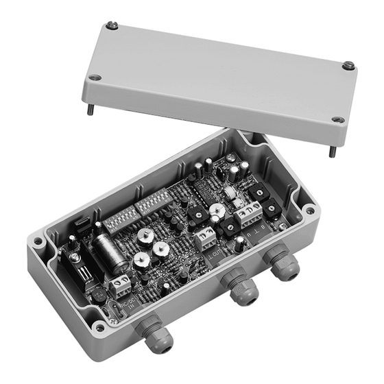
Konfiguration des TWRB/TWRR-Empfängers Konfigurationsanschlüße und -trimmers Im folgenden Bild die Konfigurationsanschlüße und -trimmers feststellen: LF-III-Endeinstellung HF-III-Endeinstellung Versorgung AC / DC Standanzeiger auf dem Video-Signal MF-III-Endeinstellung Versorgungsanzeiger Video- Ausgang LF-Gewinneinstellung Regler des linearen Gewinns HF-Gewinneinstellung Bifilarer Eingang HF-Schwächung (kurze Distanzen) Symmetrie-Einstellung Einstellung der Eingangsimpedanz Konfigurationsprozedur Die folgenden Arbeitsschritte sind, sofern nicht anders vermerkt, ohne Stromversorgung durchzuführen... -
Seite 34: Einstellung Der Eingangsimpedanz
6. Den Switch 16 von SW2 in die ON- Position bringen 7. Die Trimmer TC1,TC2,TC3,TC4 auf Mindestkapazitätswerte einstellen. Einstellung der Eingangsimpedanz Die Eingangsimpedanz nimmt verschiedene Werte je nach der Kabelart ein, die für die Übertragung des Video- Signals von der TWT-Einheit zum TWRB/TWRR-Empfänger verwendet wird: Hier einwirken : Trimmer TP1 Einstellungen : Man muß... -
Seite 35: Anschlüße
Anschlüße Installationsbeispiel Das Video-Signal der Fernsehkamera im Eingang zum TWT-Sender wird auf dem Monitor angezeigt, der am TWRB/TWRR-Empfänger im Ausgang angeschlossen ist; das Video-Signal wird durch ein bifilares Kabel übertragen: VERWENDETES MATERIAL Video-Teil: TWRB/TWRR • 1 Monitor • 1 Fernsehkamera •... -
Seite 36: Kabeltyp
Kabeltyp Es muß ein Kabel des Typs UTP (Unshielded Twisted Pair) Kat. 5 (gemäß den Standards TIA/EIA 568A und ISO/IEC 11801 definiert) verwendet werden. Mit diesem Kabel kann man größere Entfernungen abdecken und es ist auch möglich mehrere Videosignale und/oder Telemetriesignale (höchstens 4) durch einem selbsten Kabel laufen lassen. -
Seite 37: Wartung
Wartung Der TWRB/TWRR-Empfänger bedarf keiner besonderen Wartung. Es ist ratsam, sie auf einer festen Unterlage aufgestellt zu verwenden, mit den Strom- und Anschlußkabeln in einer Position, in der sie den Operator nicht behindern können. Problemlösung Der TWRB/TWRR-Empfänger zeichnet sich durch extrem einfache Anwendung aus. Trotzdem können während der Installationsphase sowie auch während des Betriebes Probleme entstehen.