Inhaltsverzeichnis
Werbung
Verfügbare Sprachen
Verfügbare Sprachen
Quicklinks
Version 1.0
Published December 2015
Copyright©2015 ASRock INC. All rights reserved.
Copyright Notice:
No part of this documentation may be reproduced, transcribed, transmitted, or
translated in any language, in any form or by any means, except duplication of
documentation by the purchaser for backup purpose, without written consent of
ASRock Inc.
Products and corporate names appearing in this documentation may or may not
be registered trademarks or copyrights of their respective companies, and are used
only for identification or explanation and to the owners' benefit, without intent to
infringe.
Disclaimer:
Specifications and information contained in this documentation are furnished for
informational use only and subject to change without notice, and should not be
constructed as a commitment by ASRock. ASRock assumes no responsibility for
any errors or omissions that may appear in this documentation.
With respect to the contents of this documentation, ASRock does not provide
warranty of any kind, either expressed or implied, including but not limited to
the implied warranties or conditions of merchantability or fitness for a particular
purpose.
In no event shall ASRock, its directors, officers, employees, or agents be liable for
any indirect, special, incidental, or consequential damages (including damages for
loss of profits, loss of business, loss of data, interruption of business and the like),
even if ASRock has been advised of the possibility of such damages arising from any
defect or error in the documentation or product.
This device complies with Part 15 of the FCC Rules. Operation is subject to the following
two conditions:
(1) this device may not cause harmful interference, and
(2) this device must accept any interference received, including interference that
may cause undesired operation.
CALIFORNIA, USA ONLY
The Lithium battery adopted on this motherboard contains Perchlorate, a toxic substance
controlled in Perchlorate Best Management Practices (BMP) regulations passed by the
California Legislature. When you discard the Lithium battery in California, USA, please
follow the related regulations in advance.
"Perchlorate Material-special handling may apply, see www.dtsc.ca.gov/hazardouswaste/
perchlorate"
ASRock Website: http://www.asrock.com
Werbung
Inhaltsverzeichnis

Verwandte Anleitungen für ASROCK 970A-G/3.1


Inhaltszusammenfassung für ASROCK 970A-G/3.1
- Seite 1 (including damages for loss of profits, loss of business, loss of data, interruption of business and the like), even if ASRock has been advised of the possibility of such damages arising from any defect or error in the documentation or product.
- Seite 2 Manufactured under license under U.S. Patent Nos: 5,956,674; 5,974,380; 6,487,535; 7,003,467 & other U.S. and worldwide patents issued & pending. DTS, the Symbol, & DTS and the Symbol together is a registered trademark & DTS Connect, DTS Interactive, DTS Neo:PC are trademarks of DTS, Inc. Product includes software. ©...
-
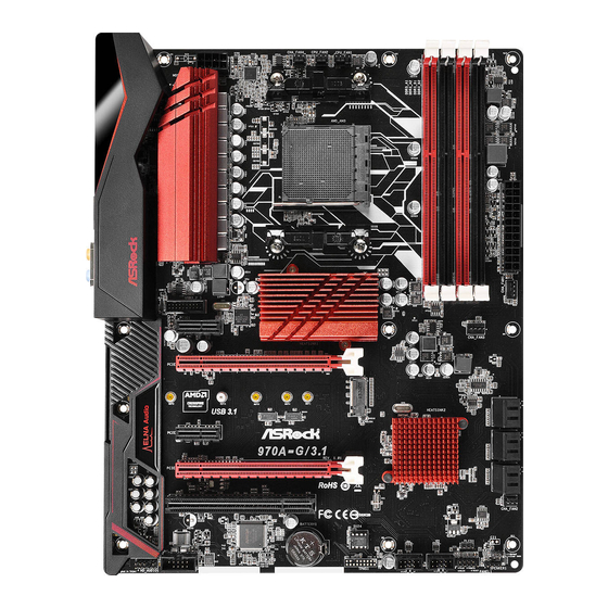
Seite 3: Motherboard-Layout
970A-G/3.1 Motherboard Layout CPU_FAN1 CHA_FAN4 CPU_FAN2 USB 2.0 T: USB2 B: USB3 USB 2.0 T: USB0 B: USB1 USB 3.1 T: USB31_TA_1 B: USB31_TC_1 USB 3.0 Top: T: USB0 RJ-45 B: USB1 USB3_2_3 Chipset CHA_FAN3 PCIE1 PCIE2 USB 3.1 PCIE3 SB950 970A-G/3.1... - Seite 4 No. Description ATX 12V Power Connector (ATX12V1) Chassis Fan Connector (CHA_FAN4) CPU Fan Connector (CPU_FAN2) CPU Fan Connector (CPU_FAN1) 2 x 240-pin DDR3 DIMM Slots (DDR3_A1, DDR3_B1) 2 x 240-pin DDR3 DIMM Slots (DDR3_A2, DDR3_B2) ATX Power Connector (ATXPWR1) Chassis Fan Connector (CHA_FAN1) Chassis Fan Connector (CHA_FAN3) SATA3 Connector (SATA3_0) SATA3 Connector (SATA3_2)
- Seite 5 970A-G/3.1 I/O Panel No. Description No. Description PS/2 Mouse Port Microphone (Pink) USB 3.1 Type-A Port (USB31_TA_1) Optical SPDIF Out Port LAN RJ-45 Port* USB 3.0 Ports (USB3_0_1) Central / Bass (Orange) USB 3.1 Type-C Port (USB31_TC_1) Rear Speaker (Black) USB 2.0 Ports (USB_0_1)
- Seite 6 * There are two LEDs on each LAN port. Please refer to the table below for the LAN port LED indications. ACT/LINK LED SPEED LED LAN Port Activity / Link LED Speed LED Status Description Status Description No Link 10Mbps connection Blinking Data Activity Orange...
-
Seite 7: Package Contents
If you require technical support related to this motherboard, please visit our website for specific information about the model you are using. You may find the latest VGA cards and CPU support list on ASRock’s website as well. ASRock website http://www.asrock.com. - Seite 8 1.2 Specifications Platform • ATX Form Factor • Solid Capacitor design • Supports Socket AM3+ processors • Supports Socket AM3 processors: AMD Phenom II X6 / X4 / X3 / X2 (except 920 / 940) / Athlon II X4 / X3 / X2 / Sempron processors • Supports 8-Core CPU • Supports UCC feature (Unlock CPU Core)
-
Seite 9: Rear Panel
• 1 x PS/2 Mouse Port • 1 x PS/2 Keyboard Port • 1 x Optical SPDIF Out Port • 4 x USB 2.0 Ports (Supports ESD Protection (ASRock Full Spike Protection)) • 1 x USB 3.1 Type-A Port (10 Gb/s) (ASMedia ASM1143) (Sup- ports ESD Protection (ASRock Full Spike Protection)) • 1 x USB 3.1 Type-C Port (10 Gb/s) (ASMedia ASM1143) (Sup-... -
Seite 10: Hardware Monitor
/ 8 32-bit / 8 64-bit / 7 32-bit / 7 64-bit / Vista 32-bit / Vista 64-bit / XP 32-bit / XP 64-bit * For the updated Windows® 10 driver, please visit ASRock’s web- site for details: http://www.asrock.com... - Seite 11 2. Due to the operating system limitation, the actual memory size may be less than 4GB for the reservation for system usage under Windows® 32-bit OS. For Windows® 64-bit OS with 64-bit CPU, there is no such limitation. You can use ASRock XFast RAM to utilize the memory that Windows® cannot use.
- Seite 12 Chapter 2 Installation This is an ATX form factor motherboard. Before you install the motherboard, study the configuration of your chassis to ensure that the motherboard fits into it. Pre-installation Precautions Take note of the following precautions before you install motherboard components or change any motherboard settings.
-
Seite 13: Installing The Cpu
970A-G/3.1 2.1 Installing the CPU Unplug all power cables before installing the CPU. - Seite 15 970A-G/3.1 2.2 Installing the CPU Fan and Heatsink After you install the CPU into this motherboard, it is necessary to install a larger heatsink and cooling fan to dissipate heat. You also need to spray thermal grease between the CPU and the heatsink to improve heat dissipation. Make sure that the CPU and the heatsink are securely fastened and in good contact with each other.
- Seite 16 2.3 Installing Memory Modules (DIMM) This motherboard provides four 240-pin DDR3 (Double Data Rate 3) DIMM slots, and supports Dual Channel Memory Technology. 1. For dual channel configuration, you always need to install identical (the same brand, speed, size and chip-type) DDR3 DIMM pairs. 2.
- Seite 17 970A-G/3.1...
- Seite 18 2.4 Expansion Slots (PCI and PCI Express Slots) There is 1 PCI slot and 4 PCI Express slots on the motherboard. Before installing an expansion card, please make sure that the power supply is switched off or the power cord is unplugged. Please read the documentation of the expansion card and make necessary hardware settings for the card before you start the installation.
- Seite 19 970A-G/3.1 2.5 Jumpers Setup The illustration shows how jumpers are setup. When the jumper cap is placed on the pins, the jumper is “Short”. If no jumper cap is placed on the pins, the jumper is “Open”. The illustration shows a 3-pin jumper whose pin1 and pin2 are “Short”...
- Seite 20 2.6 Onboard Headers and Connectors Onboard headers and connectors are NOT jumpers. Do NOT place jumper caps over these headers and connectors. Placing jumper caps over the headers and connectors will cause permanent damage to the motherboard. System Panel Header Connect the power PLED+ PLED-...
- Seite 21 970A-G/3.1 Power LED Header Please connect the chassis (3-pin PLED1) power LED to this header PLED- PLED+ PLED+ (see p.1, No. 17) to indicate the system’s power status. Serial ATA3 Connectors These six SATA3 (SATA3_0: connectors support SATA see p.1, No. 10)
- Seite 22 Front Panel Audio Header This header is for PRESENCE# MIC_RET (9-pin HD_AUDIO1) connecting audio devices OUT_RET (see p.1, No. 24) to the front audio panel. OUT2_L J_SENSE OUT2_R MIC2_R MIC2_L 1. High Definition Audio supports Jack Sensing, but the panel wire on the chassis must support HDA to function correctly.
- Seite 23 970A-G/3.1 CPU Fan Connectors This motherboard pro- FAN_SPEED_CONTROL FAN_SPEED (4-pin CPU_FAN1) vides a 4-Pin CPU fan +12V (see p.1, No. 4) (Quiet Fan) connector. If you plan to connect a (3-pin CPU_FAN2) 3-Pin CPU fan, please FAN_SPEED FAN_VOLTAGE (see p.1, No. 3) connect it to Pin 1-3.
- Seite 24 2.7 M.2_SSD (NGFF) Module Installation Guide The M.2, also known as the Next Generation Form Factor (NGFF), is a small size and versatile card edge connector that aims to replace mPCIe. The M.2_SSD (NGFF) Socket 3 can accommodate a M.2 PCI Express module up to Gen 2 x4 (20 Gb/s). Installing the M.2_SSD (NGFF) Module Step 1 Prepare a M.2_SSD (NGFF) module.
- Seite 25 970A-G/3.1 Step 4 Hand tighten the standoff into the desired NUT on the motherboard. Step 5 A l ig n a nd gent ly i nser t t he M. 2 (NGFF) SSD module into the M.2 slot. Please be aware that the M.2 (NGFF) SSD module only fits in one orientation.
-
Seite 26: Einleitung
1 Einleitung Vielen Dank, dass Sie sich für die 970A-G/3.1 von ASRock entschieden haben – ein zuverlässiges Motherboard, das konsequent unter der strengen Qualitätskontrolle von ASRock hergestellt wurde. Es liefert ausgezeichnete Leistung mit robustem Design, das ASRocks Streben nach Qualität und Beständigkeit erfüllt. -
Seite 27: Technische Daten
970A-G/3.1 1.2 Technische Daten Plattform • ATX-Formfaktor • Solides Kondensatordesign Prozessor • Unterstützung von Socket AM3+-Prozessoren • Unterstützung von Socket AM3-Prozessoren: AMD Phenom II X6 / X4 / X3 / X2 (außer 920 / 940) / Athlon X4 / X3 / X2 / Sempron-Prozessor • Acht-Kern-CPU-bereit... - Seite 28 • 4 x USB 2.0-Ports (unterstützt Schutz gegen elektrostatische Entladung (ASRock Full Spike Protection)) • 1 x USB 3.1-Typ-A-Port (10 Gb/s) (ASMedia ASM1143) (unter- stützt Schutz gegen elektrostatische Entladung (ASRock Full Spike Protection)) • 1 x USB 3.1-Typ-C-Port (10 Gb/s) (ASMedia ASM1143) (unterstützt Schutz gegen elektrostatische Entladung (ASRock...
-
Seite 29: Anschluss
• 1 x 8-poliger 12-V-Netzanschluss • 1 x Audioanschluss an Frontblende • 2 x USB 2.0-Stiftleisten (unterstützt vier USB 2.0-Ports) (unterstützt Schutz gegen elektrostatische Entladung (ASRock Full Spike Protection)) • 1 x Etron EJ188H USB 3.0-Stiftleiste (unterstützt zwei USB 3.0-Ports) (unterstützt Schutz gegen elektrostatische Entladung... - Seite 30 4 GB betragen, da unter Windows® 32-Bit OS etwas Speicher zur Nutzung durch das System reserviert wird. Unter Windows® OS mit 64-Bit-CPU besteht diese Einschränkung nicht. Mit ASRock XFast RAM können Sie den Speicher einsetzen, den Windows® nicht nutzen kann.
-
Seite 31: Jumpereinstellung
970A-G/3.1 1.3 Jumpereinstellung Die Abbildung zeigt, wie die Jumper eingestellt werden. Wenn die Jumper-Kappe auf den Kontakten angebracht ist, ist der Jumper „kurzgeschlossen“. Wenn keine Jumper-Kappe auf den Kontakten angebracht ist, ist der Jumper „offen“. Die Abbil- dung zeigt einen 3-poligen Jumper, dessen Kontakt 1 und Kontakt 2 „kurzgeschlos- sen“... -
Seite 32: Integrierte Stiftleisten Und Anschlüsse
1.4 Integrierte Stiftleisten und Anschlüsse Integrierte Stiftleisten und Anschlüsse sind KEINE Jumper. Bringen Sie KEINE Jumper-Kappen an diesen Stiftleisten und Anschlüssen an. Durch Anbringen von Jumper-Kappen an diesen Stiftleisten und Anschlüssen können Sie das Motherboard dauerhaft beschädigen. Systemblende-Stiftleiste Verbinden Sie Netz- PLED+ PLED- (9-polig, PANEL1) - Seite 33 970A-G/3.1 Betrieb-LED-Stiftleiste Bitte verbinden Sie die (3-polig, PLED1) Betrieb-LED des Gehäuses PLED- PLED+ PLED+ (siehe S. 1, Nr. 17) zur Anzeige des System- betriebsstatus mit dieser Stiftleiste. Serial-ATA-III- Diese sechs SATA-III- Anschlüsse Anschlüsse unterstützen (SATA3_0: SATA-Datenkabel für siehe S. 1, Nr. 10) interne Speichergeräte mit...
- Seite 34 Audiostiftleiste Diese Stiftleiste dient dem PRESENCE# (Frontblende) Anschließen von Audioge- MIC_RET OUT_RET (9-polig, HD_AUDIO1) räten an der Frontblende. (siehe S. 1, Nr. 24) OUT2_L J_SENSE OUT2_R MIC2_R MIC2_L 1. High Definition Audio unterstützt Anschlusserkennung, der Draht am Gehäuse muss dazu jedoch HDA unterstützt. Bitte befolgen Sie zum Installieren Ihres Sy- stems die Anweisungen in unserer Anleitung und der Anleitung zum Gehäuse.
- Seite 35 970A-G/3.1 CPU-Lüfteranschlüsse Dieses Motherboard bietet FAN_SPEED_CONTROL FAN_SPEED (4-polig, CPU_FAN1) einen 4-poligen CPU- +12V (siehe S. 1, Nr. 4) Lüfteranschluss (lautloser Lüfter). Falls Sie einen (3-polig, CPU_FAN2) 3-poligen CPU-Lüfter FAN_SPEED (siehe S. 1, Nr. 3) anschließen möchten, FAN_VOLTAGE verbinden Sie ihn bitte mit Kontakt 1 bis 3.
-
Seite 36: Contenu De L'emballage
Internet pour plus de détails sur le modèle que vous utilisez. La liste la plus récente des cartes VGA et des processeurs pris en charge est également disponible sur le site Internet de ASRock. Site Internet ASRock http://www.asrock.com. - Seite 37 970A-G/3.1 1.2 Spécifications • Facteur de forme ATX Plateforme • Conception à condensateurs solides Processeur • Prise en charge des processeurs sur socket AM3+ • Prise en charge des processeurs sur socket AM3: Processeur Phenom II X6 / X4 / X3 / X2 (sauf 920 / 940) / Athlon II X4 / X3 / X2 / Sempron d’AMD...
- Seite 38 • 1 x port sortie optique SPDIF arrière • 4 x ports USB 2.0 (Protection contre les décharges électrostatiques (Protection complète contre les pics ASRock)) • 1 x port USB 3.1 type A (10 Gb/s) (ASMedia ASM1143) (Protection contre les décharges électrostatiques (Protection complète contre les pics ASRock))
- Seite 39 2230/2242/2260/2280/22110 M.2 PCI Express jusqu’à Gen2 x4 (20 Go/s) * Si PCIE4 est occupé par un périphérique M.2 type PCI Express, M2_1 est désactivé. * Prend en charge le kit ASRock U.2 Connec- • 1 x embase pour port COM tique • 1 x embase LED d’alimentation...
- Seite 40 être inférieure à 4 Go sous Windows® 32-bit OS. Avec Windows® OS avec CPU 64 bits, il n’y a pas ce genre de limitation. Vous pouvez utiliser ASRock XFast RAM pour utiliser la mémoire dont Windows® ne peut se servir.
- Seite 41 970A-G/3.1 1.3 Configuration des cavaliers (jumpers) L’illustration ci-dessous vous renseigne sur la configuration des cavaliers (jumpers). Lorsque le capuchon du cavalier est installé sur les broches, le cavalier est ‘court- circuité’. Si le capuchon du cavalier n’est pas installé sur les broches, le cavalier est ‘ouvert’.
- Seite 42 1.4 Embases et connecteurs de la carte mère Les embases et connecteurs situés sur la carte NE SONT PAS des cavaliers. Ne placez JAMAIS de capuchons de cavaliers sur ces embases ou connecteurs. Placer un capuchon de cavalier sur ces embases ou connecteurs endommagera irrémédiablement votre carte mère.
- Seite 43 970A-G/3.1 Embase LED Veuillez brancher le d’alimentation LED d’alimentation du PLED- PLED+ (PLED1 à 3 broches) châssis sur cette embase PLED+ (voir p.1, No. 17) pour indiquer l’état d’alimentation du système. Connecteurs Serial ATA3 Ces six connecteurs SATA3 (SATA3_0: sont compatibles avec les (voir p.1, No.
- Seite 44 Embase audio du panneau Cette embase sert au PRESENCE# frontal MIC_RET branchement des appareils OUT_RET (HD_AUDIO1 à 9 audio au panneau audio broches) frontal. OUT2_L (voir p.1, No. 24) J_SENSE OUT2_R MIC2_R MIC2_L 1. L’audio haute définition prend en charge la technologie Jack Sensing (détection de la fiche), mais le panneau grillagé...
- Seite 45 970A-G/3.1 Connecteurs du Cette carte mère est FAN_SPEED_CONTROL FAN_SPEED ventilateur du processeur dotée d’un connecteur à 4 +12V (CPU_FAN1 à 4 broches) broches pour ventilateur de (voir p.1, No. 4) processeur (Quiet Fan). Si vous envisagez de connecter FAN_SPEED FAN_VOLTAGE (CPU_FAN2 à...
-
Seite 46: Contenuto Della Confezione
Nel caso di eventuali modifiche del presente manuale, la versione aggiornata sarà disponibile sul sito Web di ASRock senza ulteriore preavviso. Per il supporto tecnico correlato a questa scheda madre, visitare il nostro sito Web per informazioni specifiche relative al modello attualmente in uso. - Seite 47 970A-G/3.1 1.2 Specifiche Piattaforma • Fattore di forma ATX • Design di condensatore solido • Supporto di processori Socket AM3+ • Supporto di processori Socket AM3: AMD Phenom X6 / X4 / X3 / X2 (fatta eccezione per 920 / 940) / Athlon II X4 / X3 / X2 / Sempron • CPU Otto-Core Ready...
- Seite 48 • Realtek RTL8111GR • Supporta Wake-On-WAN • Supporta Wake-On-LAN • Supporto la protezione da fulmini/scariche elettrostatiche (ESD) (protezione completa ASRock dai picchi di corren- • Supporta il rilevamento cavo LAN • Supporta Energy Efficient Ethernet 802.3az • Supporta PXE I/O pannello • 1 x porta mouse PS/2...
- Seite 49 ASRock dai picchi di corrente)) • 1 x header Etron EJ188H USB 3.0 (supporta 2 porte USB 3.0) (supporto protezione da scariche elettrostatiche (ESD) (protezione completa ASRock dai picchi di corrente)) Caratteristi- • BIOS legale AMI UEFI con supporto GUI che del BIOS • Supporta “Plug and Play”...
- Seite 50 4GB per l’accantonamento riservato all’uso del sistema sotto Windows® 32-bit OS. Per Windows® OS con CPU 64-bit, non c’è tale limitazione. È possibile utilizzare la RAM XFast di ASRock per utilizzare la memoria che Windows® non può utilizzare.
- Seite 51 970A-G/3.1 1.3 Impostazione jumper L'illustrazione mostra in che modo vengono impostati i jumper. Quando il cappuc- cio del jumper è posizionato sui pin, il jumper è "cortocircuitato". Se sui pin non è posizionato alcun cappuccio del jumper, il jumper è "aperto". L'illustrazione mostra un jumper a 3 pin i cui pin1 e pin2 sono "cortocircuitati"...
- Seite 52 1.4 Header e connettori sulla scheda Gli header e i connettori sulla scheda NON sono jumper. NON posizionare cappucci del jumper su questi header e connettori. Il posizionamento di cappucci del jumper su header e connettori provocherà danni permanenti alla scheda madre. Header sul pannello del Collegare l'interruttore PLED+...
- Seite 53 970A-G/3.1 Header LED di alimenta- Collegare il LED di alimen- zione tazione chassis a questo he- PLED- PLED+ (PLED1 a 3 pin) ader per indicare lo stato di PLED+ (vedere pag. 1, n. 17) alimentazione del sistema. Connettori Serial ATA3...
- Seite 54 Header audio pannello Questo header serve a PRESENCE# MIC_RET anteriore collegare i dispositivi audio OUT_RET (AUDIO1_HD a 9 pin) al pannello audio anteriore. (vedere pag. 1, n. 24) OUT2_L J_SENSE OUT2_R MIC2_R MIC2_L 1. L'audio ad alta definizione supporta le funzioni Jack sensing, ma il filo del pannello sullo chassis deve supportare HDA per funzionare correttamente.
- Seite 55 970A-G/3.1 Connettori della ventola Questa scheda madre è FAN_SPEED_CONTROL FAN_SPEED della CPU dotata di un connettore +12V (CPU_FAN1 a 4 pin) per la ventola della CPU (vedere pag. 1, n. 4) (Ventola silenziosa) a 4 pin. Se si decide di collegare una...
-
Seite 56: Contenido Del Paquete
Podrá encontrar las últimas tarjetas VGA, así como la lista de compatibilidad de la CPU, en el sitio web de ASRock. Sitio web de ASRock http://www.asrock.com. - Seite 57 970A-G/3.1 1.2 Especificaciones Plataforma • Factor de forma ATX • Diseño de los Condensadores: Solid • Compatibilidad con procesadores con conector AM3+ • Compatibilidad con procesadores con conector AM3: procesador AMD Phenom II X6 / X4 / X3 / X2 (excepto 920/ 940) / Athlon II X4 / X3 / X2 / Sempron • Compatible con CPU de ocho núcleo...
- Seite 58 • 1 puerto de salida SPDIF óptica • 4 puertos USB 2.0 (compatible con protección contra electricidad estática (protección ASRock Full Spike)) • 1 Puerto USB 3.1 Tipo A Port (10 Gb/s) (ASMedia ASM1143) (admite protección ESD (protección total contra picos)) • 1 Puerto USB 3.1 Tipo C Port (10 Gb/s) (ASMedia ASM1143)
- Seite 59 2230/2242/2260/2280/22110 M.2 PCI Express hasta Gen2 x4 (20 Gb/s) * Si PCIE4 se ocupa con un dispositivo M.2 de tipo PCI Express, M2_1 se deshabilitará. * Admiteel Kit U.2 de ASRock Conectores • 1 cabezal de puerto COM • 1 cabezal de indicador LED de alimentación • 2 conectores de ventilador de la CPU (1 de 4 pines y 1 de...
- Seite 60 • Compatible con ErP/EuP (requiere toma de alimentación compatible con ErP/EuP) * Para obtener más información acerca del producto, visite nuestro sitio web: http://www.asrock.com Tenga en cuenta que existen ciertos riesgos relacionados con el overclocking (sobreaceleración), incluyendo el ajuste de la configuración del BIOS, aplicando la Tecnología overcloking no vinculada o utilizando las herramientas de overclocking...
- Seite 61 970A-G/3.1 1.3 Instalación de los puentes La instalación muestra cómo deben instalarse los puentes. Cuando la tapa de puente se coloca en los pines, el puente queda “Corto”. Si no coloca la tapa de puente en los pines, el puente queda “Abierto”. La ilustración muestra un puente de 3 pines cuyo pin 1 y pin 2 son “Cortos”...
- Seite 62 1.4 Conectores y cabezales incorporados Los cabezales y conectores incorporados NO son puentes. NO coloque tapas de puente sobre estos cabezales y conectores. Si coloca tapas de puente sobre los cabezales y conectores dañará de forma permanente la placa base. Cabezal del panel del Conecte el interruptor PLED+...
- Seite 63 970A-G/3.1 Cabezal de indicador LED Conecte el indicador LED de alimentación de alimentación del chasis PLED- PLED+ PLED+ (PLED1 de 3 pines) a este cabezal para indicar (consulte la pág.1, N.º 17) el estado de alimentación del sistema. Conectores Serie ATA3...
- Seite 64 Cabezal de audio del Este cabezal se utiliza PRESENCE# MIC_RET panel frontal para conectar dispositivos OUT_RET (HD_AUDIO1 de 9 pines) de audio al panel de audio (consulte la pág.1, N.º 24) frontal. OUT2_L J_SENSE OUT2_R MIC2_R MIC2_L 1. El Audio de Alta Definición (HDA, en inglés) es compatible con el método de sensor de conectores, sin embargo, el cable del panel del chasis deberá...
- Seite 65 970A-G/3.1 Conectores del ventilador Esta placa base contiene FAN_SPEED_CONTROL FAN_SPEED de la CPU un conector de ventilador +12V (CPU_FAN1 de 4 pines) (ventilador silencioso) de (consulte la pág.1, N.º 4) CPU de 4 pines. Si tiene pensando conectar un FAN_SPEED...
-
Seite 66: Комплект Поставки
1 Введение Благодарим вас за приобретение надежной материнской платы ASRock 970A- G/3.1, выпускаемой под постоянным строгим контролем компании ASRock. Эта материнская плата обеспечивает великолепную производительность и характеризуется прочной конструкцией в соответствии с требованиями ком- пании ASRock в отношении качества и долговечности. - Seite 67 970A-G/3.1 1.2 Спецификация • Форм-фактор ATX Платформа • Использование твердотельных конденсаторов ЦП • Поддержка Socket AM3+ процессоров • Поддержка Socket AM3 процессоров: AMD Phenom X6 / X4 / X3 / X2 (не поддерживаются 920 / 940) / Athlon II X4 / X3 / X2 / Sempron • Поддержка...
- Seite 68 Аудио • 7.1-канальный звук высокой четкости HD Audio с защитой данных (аудиокодек Realtek ALC1150) • Поддержка Premium Blu-ray Audio • Защита от перенапряжения (ASRock Full Spike Protection) • Конденсаторы для аудиосистем ELNA • Поддержка DTS-подключения ЛВС • PCIE x1 Gigabit LAN 10/100/1000 Мб/с...
- Seite 69 64-разрядная / 7 32-разрядная / 7 64-разрядная / Vista 32-разрядная / Vista 64-разрядная / XP 32-разрядная / XP 64-разрядная * Подробные сведения об обновлении драйвера Windows® 10 представлены на веб-сайте ASRock: http://www.asrock.com Сертифи- • FCC, CE, WHQL • Совместимость с ErP/EuP (необходим блок питания, кация...
- Seite 70 DDR3 2400/2100 на этой материнской плате ознакомьтесь со списком поддерживаемых модулей памяти на нашем веб-сайте, чтобы выбрать совместимые модули памяти. Веб-сайт ASRock http://www.asrock.com 2. В силу ограничения операционной системы фактическая емкость памяти может быть меньше 4Гб для обеспечения резервного места для...
- Seite 71 970A-G/3.1 1.3 Установка перемычек Установка перемычек показана на рисунке. При установке колпачковой пере- мычки на контакты перемычка «замкнута». Если колпачковая перемычка на контакты не установлена, перемычка «разомкнута». На рисунке показана 3-контактная перемычка с замкнутыми контактами 1 и 2 при установке на...
- Seite 72 1.4 Колодки и разъемы, расположенные на материнской плате Расположенные на материнской плате колодки и разъемы перемычками НЕ являются. НЕ устанавливайте на эти колодки и разъемы колпачковые пере- мычки. Установка колпачковых перемычек на эти колодки и разъемы может вызвать неустранимое повреждение материнской платы. Колодка...
- Seite 73 970A-G/3.1 Колодка светодиодного Подключите светодиод- индикатора питания ный индикатор питания PLED- PLED+ (3-контактная, PLED1) корпуса к этой колод- PLED+ (См. стр. 1, № 17) ке, чтобы обеспечить индикацию состояния питания системы. Разъемы Serial ATA3 Эти шесть разъемов (SATA3_0: SATA3 предназначены...
- Seite 74 Аудиоколодка передней Эта колодка предна- PRESENCE# панели MIC_RET значена для подключе- OUT_RET (9-контактная, HD_ ния аудиоустройств к AUDIO1) передней аудиопанели. OUT2_L (См. стр. 1, № 24) J_SENSE OUT2_R MIC2_R MIC2_L 1. Аудиосистема высокого разрешения поддерживает функцию распознавания разъема, но для е правильной работы необходимо, чтобы провод панели корпуса...
- Seite 75 970A-G/3.1 Разъемы вентиляторов Эта материнская плата FAN_SPEED_CONTROL ЦП снабжена 4-контактным FAN_SPEED +12V (4-контактный, CPU_ разъемом для мало- FAN1) шумящего вентилятора (См. стр. 1, № 4) ЦП. Если вы собирае- тесь подключить 3-кон- (3-контактный, CPU_ тактный вентилятор FAN_SPEED FAN_VOLTAGE FAN2) охлаждения процессора, (См.
-
Seite 76: Conteúdo Da Embalagem
1 Introdução Obrigado por ter comprado a placa principal ASRock 970A-G/3.1, uma placa princi- pal fiável produzida sob os rigorosos critérios de controlo de qualidade da ASRock. Esta placa principal oferece um excelente desempenho com um design robusto em conformidade com o compromisso da ASRock em fabricar produtos de qualidade e resistentes. -
Seite 77: Especificações
970A-G/3.1 1.2 Especificações Plataforma • Formato ATX • Design de condensador sólido • Suporte para processadores AM3+ • Suporte para processadores AM3: Processador AMD • Phenom II X6 / X4 / X3 / X2 (exceto 920 / 940) / Athlon II X4 / X3 / X2 / Sempron • Preparado para CPU de oito núcleos... - Seite 78 Contra Picos ASRock)) • 1 x Porta USB 3.1 Tipo A (10 Gb/s) (ASMedia ASM1143) (Suporta Proteção ESD (Proteção Total Contra Picos ASRock)) • 1 x Porta USB 3.1 Tipo C (10 Gb/s) (ASMedia ASM1143) (Suporta Proteção ESD (Proteção Total Contra Picos ASRock)) • 2 x Portas USB 3.0 (Etron EJ188H) (Suporta Proteção ESD...
-
Seite 79: Sistema Operativo
• 1 x conector de áudio do painel frontal • 2 x terminais USB 2.0 (suporte para 4 portas USB 2.0) (Suporta Proteção ESD (Proteção Total Contra Picos ASRock)) • 1 x terminal Etron EJ188H USB 3.0 (suporte para 2 portas USB 3.0) (Suporta Proteção ESD (Proteção Total Contra Picos... - Seite 80 • Preparada para ErP/EuP (é necessária uma fonte de alimenta- ção preparada para ErP/EuP) * Para obter informações detalhadas acerca do produto, visite o nosso Web site: http://www.asrock.com Tenha em atenção que o overclocking inclui um determinado grau de risco, incluindo o ajuste das definições na BIOS, a aplicação de tecnologia Untied Overclocking ou a...
- Seite 81 970A-G/3.1 1.3 Configuração dos jumpers A imagem abaixo ilustra como os jumpers são configurados. Quando a tampa do jumper é colocada nos pinos, o jumper é "Curto". Se não for colocada uma tampa de jumper nos pinos, o jumper é "Aberto". A imagem ilustra um jumper de 3 pinos cujos pino1 e pino2 estão "Curtos"...
- Seite 82 1.4 Terminais e conectores integrados Os terminais e conectores integrados NÃO são jumpers. NÃO coloque tampas de jum- pers sobre estes terminais e conectores. Colocar tampas de jumpers sobre os terminais e conectores irá causar danos permanentes à placa principal. Terminal do painel de Ligue o botão de ali- PLED+...
- Seite 83 970A-G/3.1 Conector do LED de ali- Ligue o LED de alimen- mentação tação do chassis a este PLED- PLED+ (PLED1 de 3 pinos) terminal para indicar o PLED+ (consultar p.1, N.º 17) estado de alimentação do sistema. Conectores ATA3 de série...
- Seite 84 Terminal de áudio do Este terminal destina-se PRESENCE# MIC_RET painel frontal à ligação de dispositivos OUT_RET (HD_AUDIO1 de 9 pinos) áudio ao painel de áudio (consultar p.1, N.º 24) frontal. OUT2_L J_SENSE OUT2_R MIC2_R MIC2_L 1. O Áudio de alta definição suporta Detecção de ficha, mas o cabo de painel no chas- sis deverá...
- Seite 85 970A-G/3.1 Conectores da ventoinha Esta placa principal FAN_SPEED_CONTROL FAN_SPEED da CPU inclui um conector +12V (CPU_FAN1 de 4 pinos) de ventoinha de CPU (consultar p.1, N.º 4) (Ventoinha silenciosa) de 4 pinos. Se pretender FAN_SPEED (CPU_FAN2 de 3 pinos) FAN_VOLTAGE ligar uma ventoinha de (consultar p.1, N.º...
-
Seite 86: Ambalaj İçeriği
ASRock'ın web sitesinde yer alacaktır.. Bu anakart ile ilgili olarak teknik destek almak istiyorsanız, lütfen kullandığınız model hakkında özel bilgiler için web sitemizi ziyaret edin. En güncel VGA kartları ve CPU destek listelerini de ASRock'ın web sitesinden bulabilirsiniz. ASRock'ın web sitesi http://www.asrock.com. - Seite 87 970A-G/3.1 1.2 Özellikler Platform • ATX Form Faktörü • Katı Bağlayıcı tasarımı • Soket AM3+ işlemcileri desteği • Soket AM3 işlemcileri desteği: AMD Phenom II X6 / X4 / X3 / X2 (920 / 940 hariç) / Athlon II X4 / X3 / X2 / Sempron işlemcileri...
-
Seite 88: Arka Panel
• İçerik Koruma Özelliği ile 7.1 CH HD Ses (Realtek ALC1150 Ses Codec Bileşeni) • Üstün Blu-ray Ses desteği • Dalgalanma Koruması Destekler (ASRock Tam Ani Gerilim • Koruması) • ELNA Ses Kapakları • DTS Connect işlevini destekler • PCIE x1 Gigabit LAN 10/100/1000 Mb/s • Realtek RTL8111GR... - Seite 89 • 1 x Ön panel ses bağlayıcısı • 2 x USB 2.0 bağlantısı (4 USB 2.0 bağlantı noktasını destek- ler) (ESD Koruması Destekler (ASRock Tam Ani Gerilim Ko- ruması)) • 1 x Etron EJ188H USB 3.0 bağlantısı (2 USB 3.0 bağlantı nok- tasını...
- Seite 90 • ErP/EuP için hazır (ErP/EuP için hazır güç beslemesi gerekli- dir) * Detaylı ürün bilgisi için, lütfen web sitemizi ziyaret edin: http://www.asrock.com Lütfen, BIOS ayarlarını düzenleme, Bağımsız Hız Aşırtma Teknolojinin uygulanması ya da üçüncü kişilerin hız aşırtma araçlarının kullanılması da dahil olmak üzere tüm hız aşırtma işlemlerinin belirli bir risk taşıdığını...
- Seite 91 970A-G/3.1 1.3 Bağlantı Teli Kurulumu Çizim, bağlantı tellerinin kurulumunu göstermektedir. Tel kapağı, pimlerin üzeri- ne yerleştirildiğinde, tel "Kısa" olur. Pimlerin üzerinde tel kapağı bulunmadığında, tel "Kısa" olur. Çizim, pin1 ve pin2 alanları "Kısa" olan ve bu iki pim üzerinde bir bağlantı...
- Seite 92 1.4 Ekli Bağlantılar ve Bağlayıcılar Ekli bağlantılar ve bağlayıcılar bağlantı teli değildir. Bağlantı teli kapaklarını bu bağlantı ve bağlayıcılar üzerine yerleştirmeyin. Bağlantı teli kapaklarının bağlantılar ile bağlayıcılar üzerine yerleştirilmesi, anakarta kalıcı hasar verebilir. Sistem Paneli Bağlantısı Güç anahtarını bağlayın, PLED+ PLED- (9-pin PANEL1) kasa üzerindeki anahtar...
- Seite 93 970A-G/3.1 Güç LED Bağlantısı Sistemin güç durumunun (3-pin PLED1) belirtilmesi için lütfen PLED- PLED+ (bkz. sf.1, No. 17) güç LED'ini bu bağlantıya PLED+ takın. Seri ATA3 Bağlayıcıları Bu altı SATA3 bağlayıcısı, (SATA3_0: veri aktarım hızı 6,0 Gb/ bkz. sf.1, No. 10)
- Seite 94 Ön Panel Ses Bağlantısı Bu bağlantı, ses aygıt- PRESENCE# MIC_RET (9-pin HD_AUDIO1) larının ön ses paneline OUT_RET (bkz. sf.1, No. 24) bağlanması içindir. OUT2_L J_SENSE OUT2_R MIC2_R MIC2_L 1. Yüksek Tanımlı Ses, Jak Algılama özelliğini destekler, ancak bu işlevin düzgün çalışabilmesi için kasa üzerindeki panel kablosunun HDA işlevini desteklemesi gerekmektedir.
- Seite 95 970A-G/3.1 CPU Fan Bağlayıcıları Bu anakart, 4-Pin CPU FAN_SPEED_CONTROL FAN_SPEED (4-pin CPU_FAN1) fan (Sessiz Fan) bağlayıcısı +12V (bkz sf.1, No. 4) sağlamaktadır. 3-Pin CPU fan bağlamak istiyorsanız, (3-pin CPU_FAN2) lütfen Pin 1-3'ü kullanın. FAN_SPEED FAN_VOLTAGE (bkz sf.1, No. 3) ATX Güç Bağlayıcısı...
- Seite 96 ASRock 970A-G/3.1 마더보드를 구입해 주셔서 감사합니다. 이 마더보드는 ASRock 의 일관되고 엄격한 품질관리 하에 생산되어 신뢰성이 우수합니다 . 품질과 내구성 에 대한 ASRock 의 기준에 부합하는 우수한 성능과 견고한 설계를 제공합니다 . 마더보드 규격과 BIOS 소프트웨어를 업데이트할 수도 있기 때문에 , 이 설명서의 내...
- Seite 97 970A-G/3.1 1.2 규격 • ATX 폼 팩터 플랫폼 • 솔리드 콘덴서 구조 • Socket AM3+ 프로세서에 대한 지원 • Socket AM3 프로세서에 대한 지원 : AMD Phenom II X6 / X4 / X3 / X2 (920/940 제외 ) / Athlon II X4 / X3 / X2 / Sempron 프로세서...
- Seite 98 • PS/2 키보드 포트 1 개 • 광학 SPDIF 출력 포트 1 개 • USB 2.0 포트 4 개 (ESD 보호 지원 (ASRock 풀 스파이크 보호 )) • USB 3.1 타입 A 포트 1 개 (10 Gb/s) (ASMedia ASM1143) (ESD 보호...
- Seite 99 64 비트 / XP 32 비트 / XP 64 비트 * 업데이트된 Windows® 10 드라이브의 자세한 내용은 다음의 ASRock 웹사이트를 참조하십시오 . http://www.asrock.com • FCC, CE, WHQL 인증 • ErP/EuP 사용 가능 (ErP/EuP 사용 가능 전원공급장치 필요 ) * 자세한 제품 정보에 대해서는 당사 웹사이트를 참조하십시오 : http://www.asrock.com...
- Seite 100 2. 운영 체제 한계 때문에 Windows® 32 비트 OS 에서 시스템 용도로 예약된 실제 메모리 크기는 4 GB 이하일 수 있습니다 . 64 비트 CPU 와 Windows® OS 의 경우 그런 한계가 없습니다 . ASRock XFast RAM 을 사용하여 Windows®가 사용할 수 없는 메모리를 이용할 수 있습니다 .
- Seite 101 970A-G/3.1 1.3 점퍼 설정 그림은 점퍼를 어떻게 설정하는지 보여줍니다. 점퍼 캡을 핀에 씌우면 점퍼가 “단락” 됩니다 . 점퍼 캡을 핀에 씌우지 않으면 점퍼가 “단선”됩니다 . 그림은 3 핀 점퍼를 보 여주며 핀 1 과 핀 2 는 점퍼 캡을 씌울 때 “단락”됩니다 .
- Seite 102 1.4 온보드 헤더 및 커넥터 온보드 헤더와 커넥터는 점퍼가 아닙니다 . 점퍼 캡을 온보드 헤더와 커넥터에 씌우 지 마십시오 . 점퍼 캡을 온보드 헤더와 커넥터에 씌우면 마더보드가 영구적으로 손 상됩니다 . 섀시의 전원 스위치 , 리셋 시스템 패널 헤더 PLED+ PLED- (9 핀...
- Seite 103 970A-G/3.1 전원 LED 헤더 시스템 전원 상태를 나타 (3 핀 PLED1) 내려면 섀시 전원 LED 를 PLED- PLED+ PLED+ (1 페이지 , 17 번 항목 참 이 헤더에 연결하십시오 . 조 ) 시리얼 ATA3 커넥터 이들 6 개의 SATA3 커넥...
- Seite 104 전면 패널 오디오 헤더 이 헤더는 오디오 장치를 PRESENCE# MIC_RET (9 핀 HD_AUDIO1) 전면 오디오 패널에 연결 OUT_RET (1 페이지 , 24 번 항목 참 하는 데 사용됩니다 . 조 ) OUT2_L J_SENSE OUT2_R MIC2_R MIC2_L 1. 고음질 오디오는 잭 감지를 지원하지만 올바르게 작동하려면 섀시의 패널 와이어 가...
- Seite 105 970A-G/3.1 CPU 팬 커넥터 이 마더보드에는 4 핀 FAN_SPEED_CONTROL FAN_SPEED (4 핀 CPU_FAN1) CPU 팬 ( 저소음 팬 ) 커넥 +12V (1 페이지 , 4 번 항목 참조 ) 터가 탑재되어 있습니다 . 3 핀 CPU 팬을 연결하려 (3 핀 CPU_FAN2) 는...
- Seite 106 な場合には、 ご使用のモデルについての詳細情報を、 当社のウェブサイトで参照く ださい。 アスロックのウェブサイトでは、 最新の VGA カードおよび CPU サポート 一覧もご覧になれます。 アスロックウェブサイト http://www.asrock.com. 1.1 パッケージの内容 • アスロック 970A-G/3.1 マザーボード (ATX フォームファクター) • アスロック 970A-G/3.1 クイ ックインストールガイ ド • アスロック 970A-G/3.1 サポート CD • 2 x シリアル ATA (SATA) データケーブル (オプション)...
- Seite 107 970A-G/3.1 1.2 仕様 • ATX フォームファクター プラッ ト フォーム • 固体コンデンサー設計 • Socket AM3+ プロセッサのサポート • Socket AM3 プロセッサのサポート :AMD Phenom II X6 / X4 / X3 / X2(920 / 940 を除く ) / Athlon II X4 / X3 / X2 / Sempron プロセッサ...
- Seite 108 リアパネル • 1 x PS/2 キーボードポート • 1 x 光 SPDIF 出力ポート • 4 x USB 2.0 ポート ( 静電気放電 (ESD) 保護に対応 (ASRock 完全スパイク保護) • 1 x USB 3.1 Type-A ポート (10 Gb/s) (ASMedia ASM1143) (静 電気放電 (ESD) 保護に対応 (ASRock 完全スパイク保護) )...
- Seite 109 • 2 x USB 2.0 ヘッダー (4 つの USB 2.0 ポートをサポート) ( 静 電気放電 (ESD) 保護に対応 (ASRock 完全スパイク保護) • 1 x Etron EJ188H USB 3.0 ヘッダー (2 つの USB 3.0 ポートを サポート) ( 静電気放電 (ESD) 保護に対応 (ASRock 完全ス パイク保護) BIOS •...
- Seite 110 1. 2400/2100MHz メモリ速度がサポートされているかどうかは、 採用している AM3/AM3+ CPU によって異なります。 このマザーボードに DDR3 2400/2100 メ モリモジュールを採用する場合、 WEB サイトのメモリサポートリストを参照し て互換可能なメモリモジュールを見つけてくださ い。 ASRock Web サイト http://www.asrock.com 2. オペレーティングシステム制限のため、 Windows® 32 ビット OS 使用下において、 システム使用のリザーブに対する実際の記憶容量は 4GB 未満である可能性があ ります。 64 ビット CPU の Windows® OS に対しては、 そのような制限はありませ ん。 Windows® では使えないメモリを使用するために、 アスロック XFast RAM を...
- Seite 111 970A-G/3.1 1.3 ジャ ンパー設定 このイラストは、 ジャンパーの設定方法を示しています。 ジャンパーキャップがピ ンに被さっていると、 ジャンパーは 「ショート」 です。 ジャンパーキャップがピンに 被さっていない場合には、 ジャンパーは 「オープン」 です。 この図は 3 ピンのジャ ンパーを表し、 ジャンパーキャップがピン 1 とピン 2 に被さっているとき、 これら のピンは 「ショート」 です。 CMOS クリアジャンパー (CLRCMOS1) CMOS のクリア デフォルト (p.1、 No. 18 参照) CLRCMOS1 は、 CMOS のデータをクリアすることができます。 クリアして、 デフォ...
- Seite 112 1.4 オンボードのヘッダーとコネクター オンボードヘッダーとコネクターはジャンパーではありません。 これらヘッダーとコ ネクターにはジャンパーキャップを被せないでください。 ヘッダーおよびコネクター にジャンパーキャップを被せると、 マザーボードに永久損傷が起こることがありま す。 システムパネルヘッダー 電源スイ ッチを接続し、 PLED+ PLED- (9 ピンパネル 1) スイ ッチをリセットし、 下 PWRBTN# (p.1、 No. 20 参照) 記のピン割り当てに従っ て、 シャーシのシステムス RESET# テータス表示ランプをこ HDLED- のヘッダーにセットしま HDLED+ す。 ケーブルを接続すると きには、 ピンの+と-に 気をつけてください。 PWRBTN (電源スイ ッチ) : シャーシ前面パネルの電源スイ...
- Seite 113 970A-G/3.1 電源 LED ヘッダー システムの電源ステー (3 ピン PLED1) PLED- タスを表示するために、 PLED+ PLED+ (p.1、 No. 17 参照) シャーシ電源 LED をこ のヘッダーに接続してく ださい。 シリアル ATA3 コネクタ これら 6 つの SATA3 コ ネクターは、 最高 6.0 Gb/ ー (SATA3_0: 秒のデータ転送速度で内 p.1、 No. 10 参照)...
- Seite 114 フロントパネルオーディ このヘッダーは、 フロント PRESENCE# MIC_RET オヘッダー オーディオパネルにオー OUT_RET (9 ピン HD_AUDIO1) ディオデバイスを接続す (p.1、 No. 24 参照) るためのものです。 OUT2_L J_SENSE OUT2_R MIC2_R MIC2_L 1. ハイディフィニションオーディオはジャックセンシングをサポートしていますが、 正しく機能するためには、 シャーシのパネルワイヤーが HDA をサポートしてい ることが必要です。 お使いのシステムを取り付けるには、 当社のマニュアルおよ びシャーシのマニュアルの指示に従ってください。 2. AC’ 97 オーディオパネルを使用する場合には、 次のステップで、 前面パネルオー ディオヘッダーに取り付けてください。 A. Mic_IN (MIC) を MIC2_L に接続。 B.
- Seite 115 970A-G/3.1 CPU ファンコネクター このマザーボードは 4 ピ FAN_SPEED_CONTROL FAN_SPEED (4 ピン CPU_FAN1) ン CPU ファン (静音ファ +12V (p.1、 No. 4 参照) ン) コネクターを提供し ます。 3 ピンの CPU ファ (3 ピン CPU_FAN2) ンを接続する場合には、 FAN_SPEED FAN_VOLTAGE (p.1、 No. 3 参照) ピン 1-3 に接続してくださ...
- Seite 116 1 简介 感谢您购买 ASRock 970A-G/3.1 主板,这是按照 ASRock 一贯严格质量控制标准 生产的性能可靠的主板。它提供符合 ASRock 质量和耐久性承诺的精良设计和卓 越性能。 由于主板规格和 BIOS 软件可能已更新,因此, 本手册的内容可能会随时更改,恕 不另行通知。如果本手册有任何修改,则更新的版本将发布在 ASRock 网站上,我 们不会另外进行通知。如果您需要与此主板相关的技术支持,请访问我们的网站 以具体了解所用型号的信息。您也可以在 ASRock 网站上找到最新 VGA 卡和 CPU 支持列表。ASRock 网站 http://www.asrock.com。 1.1 包装清单 • ASRock 970A-G/3.1 主板 (ATX 规格尺寸) • ASRock 970A-G/3.1 主板快速安装指南...
- Seite 117 970A-G/3.1 1.2 规格 • ATX 规格尺寸 平台 • 固态电容器设计 • 支持 Socket AM3+ 處理器 • 支持 Socket AM3 處理器 : AMD Phenom II X6 / X4 / X3 / X2(920/940 除外 ) / Athlon II X4 / X3 / X2 / Sempron 處理器...
- Seite 118 • 具有内容保护功能的 7.1 CH 高清音频 (Realtek ALC1150 音 音频 频编解码器) • 优质 Blu-ray 音频支持 • 支持防突波 ( 华擎全防护 ) • ELNA 音频电容 • 支持 DTS 连接 • PCIE x1 Gigabit LAN 10/100/1000 Mb/s • Realtek RTL8111GR • 支持 Wake-On-WAN (廣域网喚醒) •...
- Seite 119 / 8 32-bit / 8 64-bit / 7 32-bit / 7 64-bit / Vista 32-bit / Vista 64-bit / XP 32-bit / XP 64-bit * 有关已更新的 Windows® 10 驱动程序,请访问 ASRock 网站 了解详情 : http://www.asrock.com • FCC、CE、WHQL 认证 • ErP/EuP 支持 (需要支持 ErP/EuP 的电源)...
- Seite 120 损坏概不负责。 1. 2400/2100MHz 內存頻率是否支持在于您使用的 AM3 CPU。如果您想在這款主 板上使用 DDR3 2400/2100 內存條 , 請查閱我們網站的內存支持列表了解兼容 的內存。 華擎網站 : http://www.asrock.com 2. 由于操作系統的限制,在 Windows® 32 位元操作系統下 ,供系統使用的實際內 存容量可能小于 4GB。對於 Windows® 操作系統搭配 64 位元 CPU 來說 , 不會存 在這樣的限制。您可以使用 ASRock XFast RAM 来利用 Windows® 不能使用的 内存。...
- Seite 121 970A-G/3.1 1.3 跳线设置 此图显示如何设置跳线。将跳线帽装到这些针脚上时,跳线 “短接” 。如果这些针 脚上没有装跳线帽,跳线 “开路” 。此图显示 3 针跳线, 当跳线帽装在针脚 1 和针 脚 2 上,它们 “短接” 。 清除 CMOS 跳线 (CLRCMOS1) 清除 CMOS 默认 ( 见第 1 页 , 第 18 个 ) CLRCMOS1 允许您清除 CMOS 中的数据。要清除和重置系统参数到默认设 置,请关闭计算机 , 从电源上拔下电源线插头。等候 15 秒后,使用跳线帽将...
- Seite 122 1.4 板载接脚和接口 板载接脚和接口不是跳线。不要将跳线帽装到这些接脚和接口上。将跳线帽装到 这些接脚和接口上将会对主板造成永久性损坏。 系统面板接脚 按照下面的针脚分配,将 PLED+ PLED- (9 针 PANEL1) PWRBTN# 机箱上的电源开关、 重置 ( 见第 1 页 , 第 20 个) 开关和系统状态指示灯 连接到此接脚。在连接线 RESET# 缆前请记下正负针脚。 HDLED- HDLED+ PWRBTN ( 电源开关 ): 连接到机箱前面板上的电源开关。您可以配置使用电源开关关闭系统的方式。 RESET ( 重置开关 ): 连接到机箱前面板上的重置开关。如果计算机死机,无法执行正常重新启动,按重 置开关重新启动计算机。 PLED (系统电源 LED) : 连接到机箱前面板上的状态指示灯...
- Seite 123 970A-G/3.1 电源 LED 接脚 请将机箱电源 LED 连接 (3 针 PLED1) PLED- 到此接脚以指示系统电源 PLED+ PLED+ ( 见第 1 页 , 第 17 个 ) 状态。 串行 ATA3 接口 这六个 SATA3 接口支持 (SATA3_0: 最高 6.0 Gb/s 数据传输 见第 1 页 , 第 10 个 ) 速率的内部存储设备的...
- Seite 124 前面板音频接脚 此接脚用于将音频设备 PRESENCE# MIC_RET (9 针 HD_AUDIO1) 连接到前音频面板。 OUT_RET ( 见第 1 页 , 第 24 个 ) OUT2_L J_SENSE OUT2_R MIC2_R MIC2_L 1. 高清音频支持插孔感测,但机箱上的面板连线必须支持 HDA 才能正常工作。请 按照我们的手册和机箱手册的说明安装系统。 2. 如果您使用 AC’ 97 音频面板,请按照以下步骤安装到前面板音频接脚: A. 将 Mic_IN (MIC) 连接到 MIC2_L. B. 将 Audio_R (RIN) 连接到 OUT2_R,将 Audio_L (LIN) 连接到 OUT2_L. C.
- Seite 125 970A-G/3.1 CPU 风扇接口 此主板提供 4 针 CPU 风 FAN_SPEED_CONTROL FAN_SPEED (4 针 CPU_FAN1) 扇 (静音风扇) 接口。如 +12V ( 见第 1 页 , 第 4 个 ) 果您打算连接 3 针 CPU 风扇,请将它连接到针脚 (3 针 CPU_FAN2) 1-3。 FAN_SPEED FAN_VOLTAGE ( 见第 1 页 , 第 3 个 ) ATX 电源接口...
- Seite 126 電子信息產品污染控制標示 依據中國發布的「電子信息產品污染控制管理辦法」及 SJ/T 11364-2006「電 子信息產品污染控制標示要求」,電子信息產品應進行標示,藉以向消費者揭 露產品中含有的有毒有害物質或元素不致發生外洩或突變從而對環境造成污染 或對人身、財產造成嚴重損害的期限。依上述規定,您可于本產品之印刷電路 板上看見圖一之標示。圖一中之數字為產品之環保使用期限。由此可知此主板 之環保使用期限為 10 年。 圖一 有毒有害物質或元素的名稱及含量說明 若您慾了解此產品的有毒有害物質或元素的名稱及含量說明,請參照以下表格 及說明。 有害物質或元素 部件名稱 鉛 (Pb) 鎘 (Cd) 汞 (Hg) 六价鉻 (Cr(VI)) 多溴聯苯 (PBB) 多溴二苯醚 (PBDE) 印刷電路板 及電子組件 外部信號連 接頭及線材 O: 表示該有毒有害物質在該部件所有均質材料中的含量均在 SJ/T 11363-2006 標準規定 的限量要求以下。 X: 表示該有毒有害物質至少在該部件的某一均質材料中的含量超出 SJ/T 11363-2006 標準 規定的限量要求,然該部件仍符合歐盟指令...
- Seite 127 感謝您購買 970A-G/3.1 主機板, 本主機板經 ASRock 嚴格品管製作,是一套讓人 信賴的可靠產品。 本產品採耐用設計所展現的優異效能,完全符合 ASRock 對品 質及耐用度的承諾。 由於主機板規格及 BIOS 軟體可能會更新,所以本手冊內容如有變更恕不另行通 知。如本手冊有任何修改,可至 ASRock 網站逕行取得更新版本,不另外通知。若 您需要與本主機板相關的技術支援,請上我們的網站瞭解有關您使用機型的特定 資訊。您也可以在 ASRock 網站找到最新的 VGA 卡及 CPU 支援清單。ASRock 網 站 http://www.asrock.com. 1.1 包裝內容 • ASRock 970A-G/3.1 主機板 (ATX 尺寸 ) • ASRock 970A-G/3.1 快速安裝指南 • ASRock 970A-G/3.1 支援光碟...
- Seite 128 1.2 規格 • ATX 尺寸 平台 • 固態電容設計 • 支援 Socket AM3+ 處理器 • 支援 Socket AM3 處理器 : AMD Phenom II X6 / X4 / X3 / X2(920 / 940 除外 ) / Athlon II X4 / X3 / X2 / Sempron 處理器 •...
- Seite 129 970A-G/3.1 • 7.1 CH HD 音訊含內容保護 (Realtek ALC1150 音訊轉碼器) 音訊 功能 • 高階藍光音訊支援 • 支援防突波 ( 華擎全防護 ) • ELNA 音響級電容 • 支援 DTS Connect • PCIE x1 Gigabit LAN 10/100/1000 Mb/s • Realtek RTL8111GR • 支援遠端開機 • 支援網路喚醒 • 支援防雷擊 / 防 ESD 靜電 ( 華擎全防護 ) •...
- Seite 130 64 位元 / 8 32 位元 / 8 64 位元 / 7 32 位元 / 7 64 位元 / Vista 32 位元 / Vista 64 位元 / XP 32 位元 / XP 64 位元 * 關於最新 Windows® 10 驅動程式的詳細資訊,請瀏覽 ASRock 網站:http://www.asrock.com • FCC、CE、WHQL 認證 • ErP/EuP Ready (需具備 ErP/EuP ready 電源供應器) * 如需產品詳細資訊,請造訪我們的網站: http://www.asrock.com...
- Seite 131 者甚至會對您系統的元件及裝置造成傷害。您應自行負擔超頻風險及成本。我們 對於因超頻所造成的可能損害概不負責。 1. 2400/2100MHz 記憶體頻率是否支援在於您使用的 AM3/AM3+ CPU。如果您想 在這款主板上使用 DDR3 2400/2100 記憶體 , 請查閱我們網站的記憶體支援列 表了解相容的記憶體。 華擎網站 : http://www.asrock.com 2. 由於作業系統的限制,在 Windows® 32 位元作業系統,供系統使用的實際記憶 體容量可能小於 4GB。對於 Windows® 作業系統搭配 64 位元 CPU 來說 , 不會 存在這樣的限制。您可使用 ASRock XFast RAM 運用 Windows® 無法使用的記 憶體。...
- Seite 132 1.3 跳線設定 圖例顯示設定跳線的方式 。當跳線帽套在針腳上時,該跳線為 「短路」 。若沒有跳 線帽套在針腳上,該跳線為 「開啟」 。圖例顯示當 3-pin 跳線的跳線帽套在 pin1 及 pin2 時,這兩個針腳皆為 「短路」 。 清除 CMOS 跳線 (CLRCMOS1) 清除 CMOS 預設 ( 請參閱第 1 頁 ,編號 18) 您可利用 CLRCMOS1 清除 CMOS 中的資料。若要清除及重設系統參數為預設 設定 ,請先關閉電腦電源,再拔下電源供應器的電源線。在等待 15 秒後,請使 用跳線帽讓 CLRCMOS1 上的 pin2 及 pin3 短路約 5 秒。不過,請不要在更新 BIOS 後立即清除...
- Seite 133 970A-G/3.1 1.4 板載排針及接頭 板載排針及接頭都不是跳線。請勿將跳線帽套在這些排針及接頭上。將跳線帽套 在排針及接頭上,將造成主機板永久性的受損。 系統面板排針 請依照以下的針腳排列 PLED+ PLED- (9-pin PANEL1) 將機殼上的電源開關、 PWRBTN# ( 請參閱第 1 頁 , 編號 20) 重設開關及系統狀態指 示燈連接至此排針。在 連接纜線之前請注意正 RESET# HDLED- 負針腳。 HDLED+ PWRBTN (電源開關) : 連接至機殼前面板上的電源開關。您可設定使用電源開關關閉系統電源的方式。 RESET (重設開關) : 連接至機殼前面板上的重設開關。若電腦凍結且無法執行正常重新啟動,按下重 設開關即可重新啟動電腦。 PLED (系統電源 LED) :...
- Seite 134 電源 LED 排針 請將機殼電源 LED 連 (3-pin PLED1) 接至此排針, 以 指示系 PLED- PLED+ PLED+ ( 請參閱第 1 頁 ,編號 17) 統的電源狀態。 Serial ATA3 接頭 這六組 SATA3 接頭皆 (SATA3_0: 支援內部儲存裝置的 請參閱第 1 頁 ,編號 10) SATA 資料纜線,最高 (SATA3_1 : 可達 6.0 Gb/s 資料傳輸 請參閱第...
- Seite 135 970A-G/3.1 前面板音訊排針 本排針適用於連接音訊 PRESENCE# MIC_RET (9-pin HD_AUDIO1) 裝置至前面板音訊。 OUT_RET ( 請參閱第 1 頁 ,編號 24) OUT2_L J_SENSE OUT2_R MIC2_R MIC2_L 1. 高解析度音訊支援智慧型音效介面偵測 (Jack Sensing),但機殼上的面板線必須 支援 HDA 才能正確運作。請依本手冊及機殼手冊說明安裝系統。 2. 若您使用 AC' 97 音訊面板,請按照以下步驟安裝至前面板音訊排針: A. 將 Mic_IN (MIC) 連接至 MIC2_L。 B. 將 Audio_R (RIN) 連接至 OUT2_R 且將 Audio_L (LIN) 連接至 OUT2_L。...
- Seite 136 CPU 風扇接頭 本主機板配備 4-Pin FAN_SPEED_CONTROL FAN_SPEED (4-pin CPU_FAN1) CPU 風扇 ( 靜音風扇 ) +12V ( 請參閱第 1 頁 , 編號 4) 接頭。若您計畫連接 3-Pin CPU 風扇,請接 (3-pin CPU_FAN2) 至 Pin 1-3。 FAN_SPEED FAN_VOLTAGE ( 請參閱第 1 頁 , 編號 3) ATX 電源接頭 本主機板配備一組...
- Seite 137 970A-G/3.1 Spesifikasi Platform • Bentuk dan Ukuran ATX • Desain Kapasitor Solid • Stopkontak AM3+ • Stopkontak AM3 untuk AMD Phenom II X6 / X4 / X3 / X2 (kecuali 920 / 940) / Athlon II X4 / X3 / X2 / Sempron processor • Dukungan CPUT Delapan Inti...
- Seite 138 Belakang • 1 x Port Keyboard PS/2 • 1 x Port SPDIF Out Optik • 4 x Port USB 2.0 (Mendukung Perlindungan ESD (ASRock Full Spike Protection)) • 1 x USB 3.1 Port Tipe A (10 Gb/s) (ASMedia ASM1143) (Mendukung Perlindungan ESD (Perlindungan ASRock Full Spike)) • 1 x USB 3.1 Port Tipe C (10 Gb/s) (ASMedia ASM1143)
- Seite 139 • 2 x Header USB 2.0 (mendukung 4 port USB 2.0) (Mendukung Perlindungan ESD (ASRock Full Spike Protection)) • 1 x Header Etron EJ188H USB 3.0 (mendukung 2 port USB 3.0) (Mendukung Perlindungan ESD (ASRock Full Spike Protection)) Fitur • AMI UEFI Legal BIOS dengan dukungan GUI BIOS • Menggunakan “Plug and Play”...
- Seite 140 * Untuk driver Windows® 10 terbaru, kunjungi situs web ASRock untuk mendapatkan info rinci: http://www.asrock. Sertifikasi • FCC, CE, WHQL • Siap untuk ErP/EuP (memerlukan catu daya untuk ErP/ EuP) * Untuk informasi rinci tentang produk, kunjungi situs web kami: http://www.asrock.com...
-
Seite 141: Contact Information
Contact Information If you need to contact ASRock or want to know more about ASRock, you’re welcome to visit ASRock’s website at http://www.asrock.com; or you may contact your dealer for further information. For technical questions, please submit a support request form at http://www.asrock.com/support/tsd.asp...