Werbung
Verfügbare Sprachen
Verfügbare Sprachen
Quicklinks
INSTRUCTION
EN
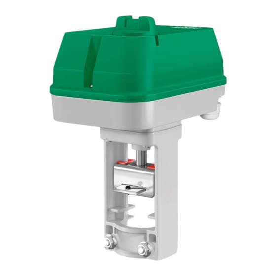
RVAN10-24A
i
Read this instruction before installation
and wiring of the product
Valve actuator for 0(2)...10 V control
RVAN10-24A is a valve actuator designed for control of Regin valves.
The actuator has automatic self stroke adjustment and can be oper-
ated manually.
Technical data
Supply voltage
24 V AC ±15 %, 50/60 Hz
or 24 V DC ±15 %
Control signal
0(2)...10 V DC
Max. power consumption
6.2 W / 17.4 VA
Stroke
10...30 mm
Stroke time
1.5 s/mm
Force
1000 N
Ambient temperature
0...50°C
Storage temperature
-40...80°C
Ambient humidity
10...90 % RH
Dimensions (WxHxD)
198 x 266 x 133 mm
Protection class
IP54
Installation
If the valve stem adaptor and valve throat adaptor are not already mount-
ed on the valve, mount them. Pull the valve stem out as far as possible.
Remove the locking bolt (U-bolt) from the actuator yoke. Insert the valve
stem into the yoke and make sure that the stem adaptor engages the hole
in the angled iron of the actuator drive spindle.
The groove in the valve throat adaptor must be made to line up with the
U-bolt mounting holes on the actuator. If the spindle needs moving in or
out for this to happen, depress the central part of the manual button and
turn it clockwise for the actuator spindle to extend, and anti-clockwise for
it to retract (see Manual override). When the valve is in the correct posi-
tion, insert the U-bolt. Tighten the bolt nuts until the valve is firmly gripped.
Disassembly in reverse order.
Mounting positions
90º
Wiring
U
M
5
4
Measuring voltage
for position indication
U 0...10 V DC
Signal neutral
Y 0(2)...10 V DC
Control signal from
controller
Stroke and end position calibration
Stroke and end position calibration is not necessary due to a construction
utilizing end position stops. When the valve reaches the end position, a
force is generated. Once the force of the actuator reaches a predefined
level, the limit switch automatically halts the drive motor.
RVAN10-24A
Override
Activation of the override input will force the valve to the maximum
open position.
Manual override
90º
To manually set the valve position, first depress the central part of the
knob, until it clicks and remains depressed (1 in the figure). Then the
valve position can be changed manually by turning the knob (2 in the
figure). When the knob is turned clockwise, the drive rod is pushed
outwards and when the knob is turned anti-clockwise, the drive rod is
pulled inwards.
To return to normal operation, set the knob so that it is in line with the
text "Auto" on the cover. Then depress the outer parts of the knob (3
in the figure). The central depressed part will pop out, and the actua-
G0
G
B
Y
tor will return to normal operation.
Note: After any manual operation the actuator will always run through
3
2
1
6
a zero point calibration.
DIP switches
There are six DIP switches for setting different functions. Follow the
table below for setting the DIP switches.
Adjusted settings will be valid only after the next power-on.
1 (On)
SW1
Spindle down when the
valve is closed
SW2
LOG
24 V AC/DC
SW3
Y = 2...10 V DC
SW4
Reverse operation
SW5
Y signal split in accordance
with the setting of SW6
SW6
5(6)...10 V = 0...100 %
0 (Off)
Spindle up when the valve is
closed (FS=factory setting)
LIN (FS)
Y = 0...10 V DC (FS)
Direct operation (FS)
No split function (FS)
0(2)...5(6) V = 0...100 % (FS)
1
Werbung

Verwandte Anleitungen für Regin RVAN10-24A


Inhaltszusammenfassung für Regin RVAN10-24A
- Seite 1 Note: After any manual operation the actuator will always run through RVAN10-24A is a valve actuator designed for control of Regin valves. a zero point calibration. The actuator has automatic self stroke adjustment and can be oper- ated manually.
-
Seite 2: Installation
Off: Unchanged valve characteristics. The actuator moves linearly in RVAN10-24A är ett ventilställdon för styrning av Regins ventilsorti- relation to the control signal. ment. Ställdonet har automatisk slaglängdsjustering och går att styra EMC emissions &... - Seite 3 0(2)...5(6) V = 0...100 % (FI) mer att gälla först efter nästa spänningstillslag. Fast rött och grönt ljus Ändläget har nåtts Rött ljus som blinkar långsamt Driftläget överstyrs Fast rött ljus Felaktigt handhavande, an- tingen var installationen felaktig eller så gick ventilens slaglängd förlorad RVAN10-24A...
- Seite 4 Ventilstellantrieb für 0(2)...10 V-Ansteuerung Anschluss RVAN10-24A ist ein Stellantrieb für die Ansteuerung von Regin Ventilen. EMC emissions- och immunitetsstandard Der Stellantrieb ist mit automatischer Hubanpassung und Handbedienung Produkten uppfyller kraven i EMC-direktivet ausgestattet.
-
Seite 5: Dip-Schalter
49, 12249 Berlin Tel: +49 30 77 99 40, Fax: +49 30 77 99 413 Invertierte Stellrichtung Normale Stellrichtung (WE) info@riccius-sohn.eu, www.regincontrols.com Y-Signal-Splittung entspre- Keine Splittung (WE) chend Einstellung an 5(6)...10 V = 0...100 % 0(2)...5(6) V = 0...100 % (WE) RVAN10-24A... - Seite 6 Veuillez lire cette instruction avant de procéder à l’installation et au raccordement de l’appareil. Moteur de vanne pour contrôle 0(2)...10 V L’actionneur RVAN10-24A est prévu pour le pilotage de vannes Raccordement Regin. L’ajustement de la course est automatique. Le moteur dispose d’une commande manuelle.
- Seite 7 à la prochaine mise SW3 Signal de commande sous tension. Regin FRANCE, 32 rue Delizy, 93500 Pantin On : 2...10 V DC Off : 0...10 V DC Tél : +33(0)1 71 00 34, Fax : +33(0)1 71 46 46...