Inhaltsverzeichnis
Werbung
Verfügbare Sprachen
Verfügbare Sprachen
Werbung
Kapitel
Inhaltsverzeichnis

Verwandte Anleitungen für vds EGO


Inhaltszusammenfassung für vds EGO
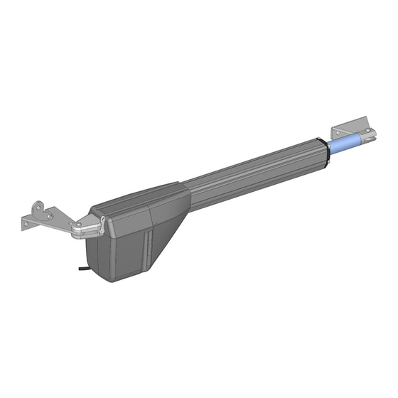
- Seite 2 ATTUATORE IRREVESIBILE PER CANCELLI E PORTE AD ANTE BATTENTI ATTENZIONE!! Prima di effettuare l'installazione, leggere attentamente questo manuale che è parte integrante di questa confezione. I nostri prodotti se installati da personale specializzato idoneo alla valutazione dei rischi, rispondono alle normative UNI EN 12453-EN 12445 Il marchio CE è...
-
Seite 3: Inhaltsverzeichnis
Composizione dell’imballo ..............Prospetto generale ................Dati tecnici ..................Dimensioni ..................Collegamento tipo e sezione cavi ............Considerazione per l’installazione ............Modalità’ di installazione ..............5-6-7 Inconvenienti : cause e soluzioni............Suggerimenti e sicurezza ..............CONTENUTO DELL’IMBALLO 1- ATTUATORE 1- KIT STAFFE DI FISSAGGIO 1- CHIAVE SBLOCCO 1- CONDENSATORE (per versioni 230Vca) -
Seite 4: Dati Tecnici
Esempio di installazione 1- Attuatori 5- Fotocellula interna 2- Fotocellula esterna 6- Quadro di comando 3- Lampeggiatore 7- Selettore a chiave 4- Antenna 8- Radiocomando DATI TECNICI 230V 200 Kg Peso Max anta 2,50 mt Lunghezza Max anta 230 Vac 24Vdc Alimentazione motore 200 W... -
Seite 5: Dimensioni
DIMENSIONI COLLEGAMENTO TIPO E SEZIONE CAVI 4X1,5mm2 ( 230Vac ) 2X1,5mm2 ( 24Vdc ) 2X0,75mm2 RX fotocellula TX fotocellula 4X0,75mm2 2X0,75mm2 4X0,75mm2 3X1,5mm2 Linea 230Vac... -
Seite 6: Considerazione Per L'installazione
CONSIDERAZIONI PER L’INSTALLAZIONE · Le operazioni di installazione e collaudo devono essere eseguite solo da personale qualificato ai fini di garantire la corretta e sicura funzionalità del cancello automatico. · La casa costruttrice, declina ogni responsabilità per i danni derivati da eventuali errate installazioni dovute ad incapacità... - Seite 7 INSTALLAZIONE PIASTRE DI FISSAGGIO Fissare la piastra posteriore al pilastro.(FIG. 1) Ancorare la parte posteriore dell’attuatore alla piastra e fissarla (FIG. 1) saldamente. ( FIG. 2) (FIG. 2) (FIG. 3) Attenzione! Nel determinare l’altezza da terra a cui fissare la piastra sul pilastro(FIG.1), tenere conto che la piastra per l’ancoraggio del pistone sul cancello deve essere fissata allo stesso livello.
-
Seite 8: Finecorsa
Regolazione finecorsa ( OPTIONAL) L’attuatore può essere dotato di finecorsa meccanico in apertura e/o in chiusura (optional). Ÿ Per effettuare la regolazione allentare le viti situate sul finecorsa e spostarlo nella posizione desiderata. Ÿ Bloccare le viti. Finecorsa Procedura di sblocco Per effettuare lo sblocco dell’attuatore inserire la chiave in dotazione nel perno . -
Seite 9: Inconvenienti-Cause E Soluzioni
INCONVENIENTI-CAUSE E SOLUZIONI INCONVENIENTE CAUSA PROBABILE SOLUZIONE Alimentazione di Controllare l’interrutore rete 230 volt assente principale Controllare eventuali selettori o comandi di Presenza di STOP di STOP. Se non utilizzati emergenza verificare ponticello su Ad un comando con ingresso contatto STOP il radiocomando o con su centralina il selettore a chiave,... - Seite 10 NOTE...
- Seite 11 NOTE...
-
Seite 12: Avvertenze Per La Sicurezza
AVVERTENZE PER LA SICUREZZA Le presenti avvertenze sono parti integranti ed essenziali del prodotto e devono essere consegnate all’utilizzatore. Leggerle attentamente in quanto forniscono importanti indicazioni riguardanti l’installazione, l’uso e la manutenzione. E’ necessario conservare il presente modulo e trasmetterlo ad eventuali subentranti nell’uso dell’impianto. L’errata installazione o l’utilizzo improprio del prodotto può... - Seite 13 I dati e le immagini sono puramente indicativi VDS si riserva il diritto di modificare in qualsiasi momento le caratteristiche dei prodotti descritti a suo insindacabile giudizio, senza alcun preavviso. Via Circolare p.i.p. N° 10 65010 Santa Teresa di Spoltore (PE) - ITALY Tel.
- Seite 14 IRREVERSIBLE OPERATOR FOR SWING GATES AND DOORS WARNING!! Before installing, thoroughly read this manual that is an integral part of the pack Our products if installed by qualified personnel capable to evaluate risks, comply with norms UNI EN 12453, EN 12445 The CE mark conforms to European directive EEC 89/336 + 92/31 + 93/68 D.L.
-
Seite 15: Packing Contents
................PACKING CONTENTS ..... VIEW OF TYPICAL AUTOMATION AND NAMES OF COMPONENTS ................... TECHNICAL DATA ..................DIMENSIONS .......... TYPICAL CONNECTION AND CABLE SECTION ........... CONSIDERATIONS FOR INSTALLATION 5-6-7 ..................INSTALLATION ................TROUBLESHOOTING ................SAFETY PRECAUTIONS PACKING CONTENTS 1- OPERATOR 1- KIT FASTENING PLATES AND RELATIVE ACCESSORIES 1- UNLOCKING KEY 1- CONDENSER (230Vca) -
Seite 16: View Of Typical Automation And Names Of Components
VIEW OF TYPICAL AUTOMATION AND NAMES OF COMPONENTS Optimal installation 1- Operator 5- Internal photocell 2- External photocell 6- Electronic control unit 3- Flashing warning light 7- Key-switch 4- Antenna 8- Remote control TECHNICAL DATA 230V 200 Kg Max. weight of gate 2,50 mt Max. -
Seite 17: Dimensions
DIMENSIONS TYPICAL CONNECTION AND CABLE SECTION 4X1,5mm2 ( 230Vac ) 2X1,5mm2 ( 24Vdc ) 2X0,75mm2 RX Photocell TX Photocell 4X0,75mm2 2X0,75mm2 4X0,75mm2 3X1,5mm2 230V Line... -
Seite 18: Considerations For Installation
CONSIDERATIONS FOR INSTALLATION · The installation and testing operations must be performed solely by qualified per sonnel in order to guarantee the proper and safe operation of the automatic gate. · The company declines any responsibility for damage caused by incorrect installations due to incompetence and/or negligence. - Seite 19 INSTALLATION OF FASTENING PLATES Fix the back plate to the pillar.(FIG. 1) Anchor the rear part of the piston to the plate and fasten it firmly.( FIG. 2) (FIG. 1) (FIG. 2) (FIG. 3) Warning! When establishing the height off the ground at which to fasten the plate to the post (fig.
-
Seite 20: Limitswitch
Limitswitch adjustment ( OPTIONAL) The actuator may be provided with mechanical limitswitches in opening and/or closing (optional). Ÿ To adjust, slacken the screws on the limitswitch and move it to the desired position. Ÿ Lock the screws.. Limitswitch Release procedure To unlock the actuator insert the supplied key into the pin. -
Seite 21: Troubleshooting
TROUBLESHOOTING SOLUTION PROBLEM PROBABLE CAUSE 230 volt mains voltage Check master switch absent Check for any STOP selectors or commands. Emergency STOP present If not used, check jumper On giving a command with on STOP contact input on the remote the control board control or with the key-switch, the gate... - Seite 22 NOTES...
- Seite 23 NOTES...
-
Seite 24: Safety Precautions
SAFETY PRECAUTIONS These warnings are an essential, integral part of the product and must be given to the user. They provide important indications on the installation, use and maintenance and must be read carefully. This form must be preserved and passed on to subsequent users of the system. The incorrect installation or improper use of the product may be dangerous. - Seite 25 The data and images are for guidance only VDS reserves the right to change at any time characteristics of the products described in its sole discretion, without notice. Via Circolare p.i.p. N° 10 65010 Santa Teresa di Spoltore (PE) - ITALY Tel.
- Seite 26 ACTUADOR IRREVERSIBLE PARA PUERTAS CON HOJAS BATIENTE. Atención! Antes de efectuar la instalación, leer atentamente el presente manual, que es parte integrante de esto producto. Nuestros productos si instalados por personal cualificado capaz de la evaluaccion de riesgos, cumplen con la norma UNI EN 12453, EN 12445 La marca CE es conforme con la directiva europea R&TTE 99/05CE...
- Seite 27 Composición embalaje ................ Prospecto general ................Datos Técnicos..................Dimensión .................... Conexiones y secciones de cables ............ Consideraciones para la instalación ............ Modalidad de instalación ..............5-6-7 Inconvenientes : causas y soluciones..........Sugerencias y seguridad ..............CONTENIDO EMBALAJE Actuador Kit placas de fijación y accesorios llave de desbloqueo Condensador (230Vca)
-
Seite 28: Datos Técnicos
PROSPECTO AUTOMATISMO TIPO Y NOMENCLATURA COMPONENTES Instalación óptima 1- Actuador 5- Fotocélula interna 2- Fotocélula externa 6- Central electrónica 3- Indicador luminoso intermitente 7- Selector de llave 4- Antena 8- Emisor DATOS TECNICOS 230V Peso máximo por hoja 200 Kg Ancho máximo de la hoja 2,50 mt Alimentación del Motor... -
Seite 29: Dimensión
DIMENSIONES CONEXION TIPO Y SECCION CABLES 4X1,5mm2 ( 230Vac ) 2X1,5mm2 ( 24Vdc ) 2X0,75mm2 RX Fotocélula TX Fotocélula 4X0,75mm2 2X0,75mm2 4X0,75mm2 3X1,5mm2 Alimentación 230 Vac. -
Seite 30: Consideraciones Para La Instalación
CONSIDERACIONES PARA LA INSTALACIÓN · Las operaciones de instalación y ensayo deben ser efectuadas únicamente por personal cualificado para garantizar un funcionamiento correcto y seguro de la cancela automática. · La Empresa, se exime de toda responsabilidad por los daños derivados de instalaciones erradas por incapacidad y/o negligencia. - Seite 31 INSTALACION DE LAS PLACAS DE FIJACION Fijar la placa suministrada en el pilar .(FIG. 1) Anclar la parte trasera del pistón a la placa y fijarla firmemente . ( FIG. 2) (FIG. 1) (FIG. 2) (FIG. 3) ¡Atención! Cuando se establece la altura desde el suelo donde fijar la placa en el pilar (FIG.1), tener en cuenta que la placa para el anclaje del pistón en la cancela debe estar fijada al mismo nivel .
- Seite 32 Final de carrera de ajuste ( OPTIONAL) El actuador puede estar provisto de final de carrera mecánicos en la apertura y/o Ÿ cierre. (optional). Para ajustar aflojar los tornillos del interruptor y moverlo a la posición deseada. Ÿ Apretar las tornillos. Ÿ...
-
Seite 33: Inconvenientes- Causas Y Soluciones
INCONVENIENTES- CAUSAS Y SOLUCIONES INCONVENIENTE CAUSA PROBABLE SOLUCION Alimentación de red 230 Controlar el interruptor volt ausente principal Controlar los selectores o mandos de STOP. Presencia de STOP de Si no utilizados, controlar emergencia en la central, el puente en entrada Ante un mando emitido contacto STOP con el radiomando o con... - Seite 34 NOTE...
- Seite 35 NOTE...
-
Seite 36: Advertencias Para La Seguridad
ADVERTENCIAS PARA LA SEGURIDAD Las presentes advertencias constituyen una parte integrante y esencial del producto y deben ser remitidas al usuario. Leerlas atentamente, ya que brindan importantes indicaciones relativas a la instalación, al uso y al mantenimiento. Es necesario conservar el presente módulo y transmitirlo a los nuevos utilizadores del equipo. - Seite 37 Los datos y las imágenes son orientativos VDS se reserva el derecho de modificar en cualquier momento de las características de los productos descritos en su única discreción, sin previo aviso. Via Circolare p.i.p. N° 10 65010 Santa Teresa di Spoltore (PE) - ITALY Tel.
- Seite 38 PISTON ELECTROMECANIQUE POUR GRILLES ET PORTES A BATTANTS ATTENTION! Avant d’effectuer l’installation, lire attentivement le présent manuel qui fait partie intégrante de cet emballage. Nos produits si installés par personnel qualifié capable d'évaluer les risques, sont conformer à la norme UNI EN 12453, EN 12445 Le marquage CE est conforme à...
-
Seite 39: Contenu De L'emballage
TABLE DES MATIÈRES Composition de l’emballage ..............Tabbleau général ................. Caractéristiques techniques ..............Dimensions ................... Branchement et section câbles ............Considérations pour l’installations ............Modalités d’installation ................. 5-6-7 Inconvénients: causea et solutions ............. Suggestions et sécurités ..............CONTENU DE L’EMBALLAGE 1- PISTON 1- KIT PLAQUES DE FIXATION ET ACCESSOIRES... -
Seite 40: Tabbleau Général
TABLEAU AUTOMATION TYPE ET NOMENCLATURE COMPOSANTS Installation optimale 1- Pistons 5- Photocellule interne 2- Photocellule d’extérieur 6- Centrale électronique 3- Clignotant 7- Sélecteur à clef 4- Antenne 8- Commande radio CARACTÉRISTIQUES TECHNIQUES 230V 200 Kg Poids maxi battant 2,50 mt Largeur maxi battant 230 Vac 24Vdc... -
Seite 41: Dimensions
DIMENSIONS BRANCHEMENT TYPE ET SECTION CÂBLES 4X1,5mm2 (230Vac ) 2X0,75mm2 RX photocellule TX photocellule 4X0,75mm2 2X0,75mm2 4X0,75mm2 3X1,5mm2 230V Ligne... -
Seite 42: Considérations Pour L'installations
CONSIDÉRATIONS POUR L’INSTALLATION · Les opérations d’installation et de contrôle doivent être effectuées uniquement par du personnel qualifié en vue d’assurer le fonctionnement correct et sûr de la grille automatique. · La société , décline toute responsabilité concernant les dommages découlant d’une mauvaise installation par incapacité... - Seite 43 INSTALLATION DES PLAQUES DE FIXATION Fixer la plaque postérieur sur le pilon.(FIG. 1) Ancrer la partie arrière du piston à la (FIG. 1) plaque et la fixer solidement ( FIG. 2) (FIG. 2) (FIG. 3) Attention! Lorsque l'on établit la hauteur du sol à laquelle fixer la plaque sur le pilon (FIG.1), tenir compte que la plaque pour l'ancrage du piston sur la grille doit être fixée au même niveau (FIG.3) Installation de la plaque d'ancrage du piston à...
- Seite 44 Régulation de fin de course Le piston est équipé avec fin de course mécanique en ouverture (standard) et en fermeture (en option). Ÿ Pour régler, desserrer les vis sur le fin de course et le déplacer vers la position souhaitée. Ÿ...
-
Seite 45: Inconvénients: Causea Et Solutions
INCONVÉNIENTS – CAUSES ET SOLUTIONS INCONVÉNIENT CAUSE PROBABLE SOLUTION Contrôler l’interrupteur Alimentation secteur principal 230 volts absente Contrôler les commandes éventuelles ou les commandes de STOP. Présence d’un arrêt S’ils ne sont pas utilisés, d’urgence contrôler le jumper sur En présence d’une entrée contact STOP sur commande avec la la centrale... - Seite 46 NOTE...
- Seite 47 NOTE...
-
Seite 48: Consignes De Securite
CONSIGNES DE SECURITE Les présentes consignes font partie intégrante du produit et doivent être remises à l’utilisateur. Les lire attentivement car elles fournissent des indications importantes concernant l’installation, l’utilisation et l’entretien. Conserver le présent document et le remettre aux propriétaires suivants de l’installation. - Seite 49 Les données et les images sont à titre indicatif seulement VDS réserve le droit de modifier à tout moment les caractéristiques des produits décrits à sa seule discrétion, sans préavis. Via Circolare p.i.p. N° 10 65010 Santa Teresa di Spoltore (PE) - ITALY Tel.
-
Seite 50: Irreversibler Antrieb Für Drehtore Und -Türen
INSTALLATIONSHANDBUCH IRREVERSIBLER ANTRIEB FÜR DREHTORE UND -TÜREN Wenn von geschultem und Risikobewertungsfähigem Personal installiert, entsprechen unsere Produkte der Bestimmung UNI EN 12453-EN 12445 Das EG Zeichen ist der EWG europäischen Richtlinie 89/336 + 93/68 Rechtsverordnung 04/12/1992 n.476 entsprechend... -
Seite 51: Inhalt Der Verpackung
Seiten INHALT DER VERPACKUNG..............TYPISCHER ANSCHLUSS UND NOMENKLATUR DER BESTANDTEILE ..TECHNISCHE EIGENSCHAFTEN.............. GRÖßE ....................TYPISCHER ANSCHLUSS UND KABELSCHNITT ........INSTALLATIONSÜBERLEGUNGEN............INSTALLATIONSANLEITUNG..............5-6-7 STÖRUNGSSUCHTABELLE..............SICHERHEITSANWEISUNGEN ..............INHALT DER VERPACKUNG 1- ANTRIEB 1- KIT FESTPLATTEN UND DAZUGEHÖRIGES ZUBEHÖR 1- NOTENTRIEGELUNG-HEBELSCHLÜSSEL 1- KONDENSATOR (230Vac) -
Seite 52: Typischer Anschluss Und Nomenklatur Der Bestandteile
TYPISCHER ANSCHLUSS UND NOMENKLATUR DER BESTANDTEILE Installationsvorbild 1- Antrieb 5- Innenlichtschranke 2- Außenlichtschranke 6- Electronisches Steuerung 3- Blinklicht 7- Schlüsselschalter 4- Antenne 8- Handsender TECHNISCHE EIGENSCHAFTEN 230V 200 Kg Maximales Flügelsgewicht 2,50 mt Maximale Flügelsbreite 230 Vac 24Vdc Motorstromversorgung 200 W Motorleistung 1400 2800... -
Seite 53: Größe
GRÖßE TYPISCHER ANSCHLUSS UND KABELSCHNITT 4X1,5mm2 ( 230Vac 2X0,75mm2 TX Fotozelle RX Fotozelle 4X0,75mm2 2X0,75mm2 4X0,75mm2 3X1,5mm2 230V Leitung... -
Seite 54: Installationsüberlegungen
INSTALLATIONSÜBERLEGUNGEN Ÿ Installation- und Prüfungsvorgang müssen ausschli eßlich aus geschultem Personal ausgeführt werden, um ein sicheres und richtiges Funktionieren des automatischen Tors gewährzuleisten. Ÿ Die Baufirma lehnt jede Verantwortung für die even tuell falsche, unfähigkeit- und/ oder fahrlässigkeitbedingte Installation ab. Ÿ... -
Seite 55: Installation Der Zum Kolben Gehörenden Ankerplatte An Den Tor
INSTALLATION DER FESTPLATTEN Befestigen Sie die Hinterplatte an den Pfeiler. (Bild 1) Verankern Sie das Hinterteil des Kol- bens an die Platte und machen Sie es ( Bild 1) kräftig fest. (Bild 2) (Bild 2) (Bild 3) Achtung! Wenn Sie die Bodenfreiheit entscheiden, worauf die Festplatte an den Pfosten befestigt werden wird (Bild 1) , behalten Sie im Kopf, dass die Platte, die benutzt wird, um den Kolben an den Tor zu verbinden, auf derselben Höhe befestigt werden muss. -
Seite 56: Anpassung Des Endanschlags (Optional)
Anpassung des Endanschlags (OPTIONAL) Ÿ Der Antrieb mag mit Endanschläge beim Öffnen und/oder Schließen ausgestattet sein (optional). Ÿ Um den Endanschlag anzupassen, lockern Sie die dazugehörigen Schrauben und schieben Sie ihn bis die gewünschte Position. Ÿ Ziehen Sie jetzt die Schrauben fest. Endanschlag Entriegelungsvorgang Um den Antrieb zu entriegeln, stecken Sie den ausgestatteten Schlüssel in... -
Seite 57: Störungssuchtabelle
STÖRUNGSSUCHTABELLE WAHRSCHEINLICHE UR- STÖRUNG LÖSUNG SACHE Keine 230 Volt- Den Hauptschalter Netzversorgung kontrollieren Eventuelle STOP- Steuerungen kontrollieren. Not-STOP ist Wenn unbenutzt,stellen eingeschaltet Sie fest, dass der Jumper auf dem STOP -Kontakt Bei einem Impuls des positioniert ist Handsenders oder mit dem Schlüssel, öffnet Durchgebrannte Schmelz- Sie durch eine ähnliche... - Seite 58 NOTES...
- Seite 59 NOTES...
-
Seite 60: Sicherheitsanweisungen
SICHERHEITSANWEISUNGEN Die vorliegenden Anleitungen sind integrierender und wesentlicher Bestandteil vom Produkt und müssen dem Anwender geliefert werden. Lesen Sie sie sorgfältig, da sie Ihnen wichtige Informationen für die Installation, den Gebrauch und die Wartung geben. Sie müssen das vorliegenden Formblatt unbedingt aufbewahren und es eventuellen Nachanwendern übermitteln. - Seite 61 Die Beschreibungen und Abbildungen sind unverbindlich. VDS behält sich das Recht vor, jederzeit endgültig und fristlos die Eigenshaften der oben beschriebenen Produkte zu ändern. Via Circolare p.i.p. N° 10 65010 Santa Teresa di Spoltore (PE) - ITALY Tel. +39 085 4971946 - FAX +39 085 4973849...
- Seite 62 ANUAL ÉCNICO DE NSTALAÇÃO MOTOR IRREVERSÍVEL PARA PORTAS E PORTÕES DE BATENTE ATENÇÃO!! Antes de efectuar a instalação, leia atentamente este manual que é parte integrante deste equipamento Nossos produtos se instalado por pessoal qualificado, capaz de avaliar risco, cumprir UNI EN 12453, EN 12445 A marca CE está...
-
Seite 63: Conteúdo Da Embalagem
ÍNDICE Conteúdo da Embalagem ................Prospecto Geral ....................Dados Técnicos ....................Dimensões ......................Ligações e Secções dos Cabos ..............Considerações para a Instalação ..............Modalidade de Instalação 5-6-7 ................. Problemas: Causas e Soluçõe ................ Sugestões e Segurança ..................CONTEÚDO DA EMBALAGEM 1 –... -
Seite 64: Dados Técnicos
PROSPECTO DO AUTOMATISMO TIPO E NOMENCLATURA DOS COMPONENTES Instalação ideal 1- Motores 5- Fotocélulas internas 2- Fotocélulas externas 6- Quadro 3- Sinalizador 7- Selector chave 4- Antena 8- Emissor DADOS TÉCNICOS 230V 200 Kg Peso máximo do portão 2,50 mt Largura máxima do portão 230 Vac 24Vdc... - Seite 65 DIMENSÕES TIPOS DE LIGAÇÕES E SECÇÕES DE CABOS 4X1,5mm2 ( 230Vac ) 2X1,5mm2 ( 24Vdc ) 2X0,75mm2 Fotocélula RX Fotocélula RX 4X0,75mm2 2X0,75mm2 4X0,75mm2 3X1,5mm2 Linha 230V...
- Seite 66 CONSIDERAÇÕES PARA A INSTALAÇÃO Ÿ As operações de instalação e teste devem ser realizadas somente por pessoal qualificado a fim de assegurar a correcta e segura funcionalidade do portão automático. Ÿ O fabricante rejeita cada responsabilidade pelos danos derivados de qualquer instalação incorrecta devido à...
- Seite 67 Instalação dos suportes de fixação Fixar o suporte posterior ao pilar. (Fig. 1) Fixar a parte posterior do motor ao (FIG. 1) pilar e fixá-la com firmeza. (Fig. 2) (FIG. 2) (FIG. 3) Atenção! Para determinar a altura da terra a que fixar o suporte de fixação ao pilar (Fig.
- Seite 68 Ajuste do Fim de curso (Opcional) O actuador pode ser fornecida com Fim de curso mecânico de abertura e / ou fechamento (opcional). Ÿ Para ajustar, solte os parafusos do Fim de curso e movê-lo para a posição desejada. Ÿ Apertar os parafusos. Fim de curso Procedimento de desbloqueio Para efectuar o desbloqueio do motor, inserir a chave fornecida.
-
Seite 69: Inconvenientes - Causas E Soluções
INCONVENIENTES - CAUSAS E SOLUÇÕES INCONVENIENTE CAUSA PROVÁVEL SOLUÇÃO Alimentação de rede 230 Controlar o interruptor volt ausente principal Controlar quaisquer selectores ou comandos de STOP Presença de STOP de Se não for utilizado emergência verificar ponte na entrada Para um comando do contacto STOP na com o controle remoto centralina... - Seite 70 NOTAS...
- Seite 71 NOTAS...
-
Seite 72: Advertências Para A Segurança
ADVERTÊNCIAS PARA A SEGURANÇA As presentes advertências são parte integrante e essenciais do produto e deverão ser entregues ao utilizador. Leia atentamente como fornecem importantes indicações relativas à instalação, ao uso e à manutenção. É necessário conservar este formulário e transmiti-lo para qualquer utilizador no futuro. - Seite 73 Os dados e as imagens são apenas para orientação VDS reservas o direito de alterar, a qualquer tempo as características dos produtos descritos em seu exclusivo critério, sem aviso prévio. Via Circolare p.i.p. N° 10 65010 Santa Teresa di Spoltore (PE) - ITALY Tel.