TTGO TG M Installierungs-Und Gebrauchsanleitungen Und Hinweise
Vorschau ausblenden
Andere Handbücher für TG M:
Inhaltsverzeichnis
Verfügbare Sprachen
Verfügbare Sprachen
Quicklinks
TyPE: TG M, TG S
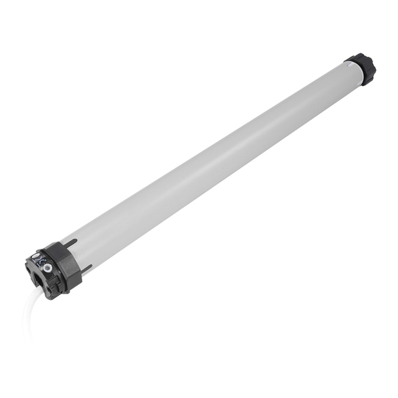
TubuLaR
MoToR
FoR SHuTTERS
aND awNINGS
EN
Instructions and warnings
for installation and use
IT
Istruzioni ed avvertenze
per l'installazione e l'uso
ZH
安装及使用说明书
FR
Instructions et avertissements
pour l'installation
et l'utilisation
ES
Instrucciones y advertencias
para la instalación y el uso
DE
Installierungs-und
Gebrauchsanleitungen
und Hinweise
PL
Instrukcje i ostrzeżenia
do instalacji i użytkowania
NL
Aanwijzingen
en aanbevelingen
voor installatie en gebruik
Inhaltsverzeichnis

Verwandte Anleitungen für TTGO TG M


Inhaltszusammenfassung für TTGO TG M
- Seite 1 Instructions and warnings for installation and use Istruzioni ed avvertenze per l’installazione e l’uso TyPE: TG M, TG S TubuLaR 安装及使用说明书 MoToR Instructions et avertissements pour l’installation FoR SHuTTERS et l’utilisation aND awNINGS Instrucciones y advertencias para la instalación y el uso...
- Seite 2 FUSE...
- Seite 3 10 mm...
- Seite 34 DEuTSCH schützt werden, um einen unerwünschten Zugang zu vermeiden. Bezüglich des Schut- zes bezieht man sich auf die Gebrauchsanleitung des Rollladens, wobei jedoch der Zu- gang für Wartungsarbeiten gewährleistet werden muss. • Bei Markisen ist es dagegen notwendig, einen waagrechten Mindestabstand von 40 cm zwischen der vollständig geöffneten Jalousie und einem eventuell davor liegenden festen Gegenstand zu garantieren. Hinweis zum Lesen dieser Gebrauchsanleitung – De afbeeldingen ter ver- • Während der Installation das Produkt vorsichtig behandeln: Quetschungen, Stöße, duidelijking van de tekst kunt u aan het begin van de handleiding vinden. Herunterfallen oder Kontakte mit jeglichen Flüssigkeiten vermeiden; keine spitzen Ge- genstände in den Motor bringen; nicht durchbohren und keine Schrauben außerhalb des Motors anbringen; das Produkt nicht in die Nähe von Wärmequellen bringen und keinen offenen Flammen aussetzen (abb. 2). HINwEISE uND Hierdoor kan het product beschadigd raken en kunnen er storingen of gevaarlijke si- VoRSICHTSMaSSNaHMEN FÜR IHRE tuaties ontstaan. In deze gevallen dient u onmiddellijk de installatie te onderbreken en SICHERHEITa contact op te nemen met de installateur/fabrikant. • Das Produkt nicht mehr zerlegen, als in diesem Handbuch angegeben ist. • Keine Änderungen an den Produktbestandteilen ausführen, außer den in diesem 1.1 •...
-
Seite 35: Installation Des Produkts
Steuervorrichtungen nicht betätigt werden; wenn diese automatisch sind, muss auch der Strom ausgeschaltet werden. INSTaLLaTIoN DES PRoDuKTS • Die Automatisierung häufigen Prüfungen unterziehen, um zu sehen, ob Störungen oder Verschleißspuren oder Schäden an Kabeln und Federn vorliegen (wenn diese vorhan- den sind). Die Automatisierung nicht verwenden, wenn sie eingestellt oder repariert werden muss; wenden Sie sich bitte ausschließlich an spezialisiertes technisches Per- sonal, um diese Probleme zu lösen 3.1 • Vorprüfungen - Anwendungslimits Achtung! - Vor der Installation die folgenden Aspekte prüfen. - Dieses Produkt steht in verschiedenen Ausführungen zur Verfügung. Jede Ausführung bESCHREIbuNG DES PRoDuKTS uND dient für ein bestimmtes Drehmoment. Jede Ausführung wurde entwickelt, um Rollläden VERwENDuNGSZwECK mit bestimmten Eigenschaften und Abmessungen und Gewichte zu automatisieren. Deshalb muss vor der Installation geprüft werden, ob die Eigenschaften des vorlie- genden Motors (Drehmoment, Drehgeschwindigkeit und Betriebszeit) für die Automa- tisierung Ihres Rollladens geeignet sind. Achtung! - Keinen Motor mit einem Das Produkt ist ein Rohrmotor für die Automatisierung eines Rollladens, einer Marki- Drehmoment über dem notwendigen installieren, um Ihren Rollla- se oder eines Sonnenschutzes. Jeder anderer Gebrauch ist untersagt! Der... - Seite 36 Achtung! – Die Trennvorrichtung muss entsprechend den Bedingun- dies nicht der Fall ist, den Anschluss unter den braunen und Schwarzen Leitern gen der Überspannungskategorie III die vollständige Trennung von umkehren. der Stromversorgung ermö glichen. Der Lasttrennschalter muss vom Antrieb aus sichtbar sein. Im gegenteiligen Fall ist ein System zu installieren, das ei n en versehentlichen oder nicht autorisierten Anschluss der EINSTELLuNG DER ENDaNSCHLÄGE Netzspannung verhindert, um jede mögliche Gefahr auszuschließen. Hinweis – Die zwei Vorrichtungen sind nicht in der Verpackung enthalten. 4.2 • Wandinstallation der Bedienschalter 5.1 • Endanschläge beim Schließen und Öffnen Warnhinweise: Während der Auf- und Abwärtsbewegung stoppt der Mo t or die Rolle automatisch, • Installieren Sie das Schaltermodul in Sichtweite des Rollladens, jedoch fern von seinen...
- Seite 37 05. Dann die Stellschraube des Endschalters „0“ allmählich in Richtung des Zeichens Achtung! – Wenn die Rolle den Punkt überschreitet, an dem der Endanschlag „1” befestigt werden soll, die Bewegung stoppen; dann die Rolle steuern, sodass „+“ drehen, bis die gewünschte Anhaltestellung „0” erreicht wird. Hinweis - bei jeder Schraubendrehung läuft der Motor weiter und hält in der neuen Position an. sie in die Startposition zurückkehrt; die Stellschraube des Endanschlags „1” ein paar Umdrehungen in Richtung des Zeichens „–” drehen, und schließlich das Ver- Den Endanschlag „1” einstellen: fahren von Punkt 07 wiederholen. 06. Die Stellschraube des Endanschlags „1” ein paar Umdrehungen in Richtung des 08. Dann die Stellschraube des Endschalters „1“ allmählich in Richtung des Zeichens Zeichens „–“ drehen. „+“ drehen, bis die gewünschte Anhaltestellung „1” erreicht wird. Hinweis – bei 07. Die Rolle so steuern, dass sich diese in Richtung der Position „1“ bewegen kann, jeder Schraubendrehung läuft der Motor weiter und hält in der neuen Position an. und warten, bis der Motor für den Einschritt des werkseitig voreingestellten Endan- schlags anhält. “0” “0” “1” “1” “0” “0” “1” “1” Deutsch – 4...
-
Seite 38: Entsorgung Des Produkts
waS IST Zu TuN, wEN... ENTSoRGuNG DES PRoDuKTS (Anleitung zur Problemlösung) Der Motor bewegt sich nicht, obwohl eine Anstiegs- oder Senkphase Dieses Produkt ist ein vervollständigender Teil der Automatisierung gesteuert wurde: und muss somit gemeinsam entsorgt werden. 1) prüfen, ob der Thermoschutz aktiviert ist; in diesem Fall abwarten, bis sich der Motor Wie bei den Installationsarbeiten müssen die Abrüstungsarbeiten am Ende der Lebens- abgekühlt hat;... -
Seite 39: Technische Eigenschaften
TECHNISCHE EIGENSCHaFTEN EG-KONFORMITäTSERKLäRUNG l Betriebsspannung und Frequenz; Strom und Leistung, Drehmoment Erklärung Nr.: 486/TTGO und Geschwindigkeit: Siehe technische Daten auf dem Etikett jedes Modells. l Motordurchmesser: 45 mm, Größe “M”; 35 mm, Größe “S”. l Nennbetriebs- Hiermit erklärt Nice S.p.A., dass das Produkt TG M den wesentlichen Anforderun- zeit: Höchstens 4 Minuten. l Schutzgrad: IP 44 (Rohrmotor). l Betriebstempe- gen und den übrigen einschlägigen Bestimmungen der Richtlinien 2006/95/EG, ratur: -20°C (min.). l An schlusskabellänge: 2,5 m 2004/108/EG entspricht (nur auf Produkte mit integriertem Empfänger anwendbar). Die EG-Konformitätserklärung kann auf der Website www.nice-service.com eingesehen Anmerkungen: und ausgedruckt oder aber von Nice S.p.A. angefordert werden. - Alle aufgeführten technischen Eigenschaften beziehen sich auf eine Umgebungstempe- ratur von 20°C (± 5°C). Ing. Luigi Paro - Der Hersteller behält sich das Recht vor, jederzeit Änderungen am Produkt vorzuneh- 24 Juli 2013 men. (Geschäftsführung)