Herunterladen Inhalt Inhalt Diese Seite drucken

Werbung

Verfügbare Sprachen

Verfügbare Sprachen

Libretto istruzioni
Instructions Booklet
Betriebsanleitung
HRW RC D
COD. 5.471.084.843
31/10/2017

Werbung

Inhaltsverzeichnis
loading

Inhaltszusammenfassung für Vortice HRW RC D

  • Seite 1 Libretto istruzioni Instructions Booklet Betriebsanleitung HRW RC D COD. 5.471.084.843 31/10/2017...
  • Seite 2: Inhaltsverzeichnis

    Remote inputs to connect with environmental the instructions given in this booklet. sensors and/or others Vortice air extractors ..12 Following these instructions will ensure a long service life Mounting schemes ......13 and overall electrical and mechanical reliability.
  • Seite 3: Sicurezza

    Vortice e richiedere, per l’eventuale riparazione, l'uso di ricambi originali Vortice. • Se il prodotto cade o riceve forti colpi farlo verificare subito presso un Centro di Assistenza Tecnica autorizzato Vortice. • L’apparecchio deve essere montato in modo da garantire che, in condizioni normali di funzionamento, nessuno possa venirsi a trovare in prossimità...
  • Seite 4: Pannello Di Comando Del Comando Remoto

    ITALIANO Pannello di Comando del Comando Remoto Fig.1 L’ apparecchio viene controllato tramite Comando Remoto cablato. Il Comando Remoto gestisce da 1 a 6 apparecchi. Il Pannello di comando è munito dei seguenti controlli (fig.1): Pulsanti: ⃝ = Pulsante SPEED; ⃝...
  • Seite 5: Impostazione Dei Parametri Di Funzionamento

    ITALIANO In modalità di Ventilazione o Recupero di calore: nel caso in cui al comando remoto siano collegate 2,3,4,5,6 unità, tali unità verranno pilotate in modo tale da garantire il bilanciamento della portata complessiva. In caso di più unità DISPARI collegate (3/5) il bilanciamento potrebbe comportare lo spegnimento a rotazione di due delle unità...
  • Seite 6: Ingressi Ausiliari Per Abbinamento Con Sensori Ambiente E/O Altri Apparecchi Estrattori Vortice

    Per compensare le portate di estrazione, è possibile collegare altri apparecchi estrattori Vortice con gli apparecchi VORT HRW 20 MONO D. Gli apparecchi estrattori Vortice sono collegabili al Comando Remoto tramite contatto pulito On/Off (privo di potenziale elettrico) sull’ Input remoto #3 presente su scheda elettronica: - Input Remoto #3 - Immissione d’...
  • Seite 7: Schemi Di Montaggio

    Morsetto femmina del ventilatore; ② Morsetto maschio della scheda elettronica; ③ Ventilatore del Vort HRW 20 Mono D. - Controllo Remoto: HRW RC D (Vedi Figura 7) ① Scheda elettronica (vista posteriore); ② Alimentazione elettrica 12 V (due soluzioni in alternativa): ⃝...
  • Seite 8: Informazione Importante Per Lo Smaltimento Ambientalmente Compatibile

    ITALIANO Informazione importante per lo smaltimento ambientalmente compatibile IN ALCUNI PAESI DELL'UNIONE EUROPEA QUESTO PRODOTTO NON RICADE NEL CAMPO DI APPLICAZIONE DELLA LEGGE NAZIONALE DI RECEPIMENTO DELLA DIRETTIVA RAEE E QUINDI NON È IN ESSI VIGENTE ALCUN OBBLIGO DI RACCOLTA DIFFERENZIATA A FINE VITA. Questo prodotto è...
  • Seite 9: Safety

    Vortice authorized Technical Support Centre without delay. • If the appliance does not function correctly or develops a fault, contact a Vortice authorized Technical Support Centre without delay. Ensure that only genuine original Vortice spares are used for any repairs.
  • Seite 10: Remote Control Control Panel

    ENGLISH Remote Control Control Panel Fig. 1 The appliance is controlled via wired Remote Control. The Remote Control manages from 1 to 6 devices. The Control panel is equipped with the following controls (fig.1): Buttons: ⃝ = button SPEED; ⃝ = button MODE;...
  • Seite 11: Setting Operating Parameters

    ENGLISH Only for VENTILATION or RECOVERY modes: In the event that 2,3,4,5,6 units are connected to the Remote Control, these units will be piloted so as to ensure the balance of the overall flow in ventilation mode with heat recovery. In the case of “ODD Number”...
  • Seite 12: Remote Inputs To Connect With Environmental Sensors And/Or Others Vortice Air Extractors

    To compensate extracted airflows, others Vortice air extractors can be connected to devices VORT HRW 20 MONO D. Others Vortice air extractors can be connected to the Remote Control by means of clean On/Off contacts on the Remote input # 3 present on the circuit board: - Remote Input #3 - Air supply at maximum speed.
  • Seite 13: Mounting Schemes

    ① FAN header terminal block; ② FAN plug terminal block; ③ Vort HRW 20 Mono D FAN. - Remote Control: HRW RC D (See Fig. 7) ① Electronic board (rear view); ② 12 V Electric supply (two alternate solutions): ⃝...
  • Seite 14: Important Information Regarding Eco-Compatible Disposal

    ENGLISH Important information concerning the environmentally compatible disposal IN CERTAIN EUROPEAN UNION COUNTRIES THIS PRODUCT DOES NOT FALL WITHIN THE REQUIREMENTS OF THE NATIONAL LAWS IMPLEMENTING DIRECTIVE WEEE, AND IN THESE COUNTRIES THE PRODUCT IS NOT SUBJECT TO SEPARATE DISPOSAL OPERATIONS AT THE END OF ITS WORKING LIFE. This product conforms to EU Directive2002/96/EC.
  • Seite 15: Sicherheit

    • Bei Betriebsstörungen und/oder defektem Gerät sollte sofort der Vortice-Vertragskundendienst aufgesucht und für eine eventuelle Reparatur Vortice-Originalersatzteile verwendet oder verlangt werden.. • Fällt das Gerät herunter oder wurde es starken Stößen ausgesetzt, muss es sofort von einem Vortice- Vertragskundendienst überprüft werden.
  • Seite 16: Display Bedienelement

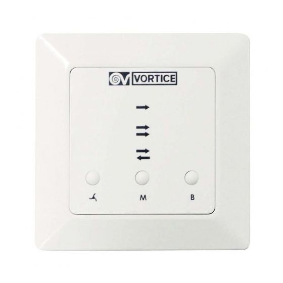
    DEUTSCH Display Bedienelement Abb. 1 Das Gerät wird mit einem kabelgebunden Bedienelement (extern) gesteuert. Das Bedienelement steuert 1 bis 6 Geräte. Das Display verfügt über folgende Funktionen (Abb.1): Tasten: ⃝ = Taste SPEED; ⃝ = Taste MODE; ⃝ = Taste BOOST; LEDs: ①...
  • Seite 17: Einstellung Der Betriebsparameter

    DEUTSCH Modus: Belüftung und Wärmerückgewinnung Wenn mit dem Bedienelement 2,3,4,5,6 Einheiten verbunden sind, werden die Geräte so gesteuert, dass bei der Betriebsart Lüftung mit Wärmerückgewinnung die Balance der Luftströme gewährleistet ist. Im Fall einer ungeraden Anzahl von Geräten (3/5) kann es im Hinblick auf die Balance der Luftströme erforderlich sein, bis zu 2 Geräte zu stoppen.
  • Seite 18: Zusatzanschlüsse Von Sensoren Und/Oder Vortice Abluftventilatoren

    Die vorgesehenen Modi werden unabhängig von der aktuellen Geschwindigkeitseinstellung aktiviert. Anschluss von externe Abluftventilatoren Um den Unterdruck der Abluftgeräte auszugleichen, können Sie die externe Vortice Abluftventilatoren in Kombination mit den VORT HRW 20 MONO D Geräte betreiben. Die externen Vortice Abluftgeräte können mithilfe der potenzialfreien Kontakte On/Off an folgenden Anschlüsse des Bedienelements angeschlossen werden: Nr.
  • Seite 19: Montageschema

    ① Buchsenklemme des Lüfters; ② Steckerklemme der Leiterplatte; ③ Lüfter des VORT HRW 20 MONO RC; - Bedienelement: Hrw Rc D (siehe Abbildung 7) ① Leiterplatte (Rückansicht); ② 12-V-Stromversorgung (zwei alternative Lösungen): ⃝ Einbau-Netzteil - für bis 4 Geräte: Plan für Wandeinbau;...
  • Seite 20: Wichtige Information Für Eine Umweltgerechte Entsorgung

    Vortice Elettrosociali S.p.A. reserves the right to make improvements to products at any time and without prior notice. La société Vortice Elettrosociali S.p.A. se réserve le droit d'apporter toutes les variations afin d'améliorer ses produits en cours de commercialisation. Die Firma Vortice Elettrosociali S.p.A. behält sich vor, alle eventuellen Verbesserungsänderungen an den Produkten des Verkaufsangebots vorzunehmen.
  • Seite 22 60x66 mm (ØxP) DIN 49073 68x47 mm (ØxP) DIN 49073 Ferrite Main supply 220-240 V 50/60Hz HRW RC D + PS24W (Cod. 21.145 + Cod. 21.187)
  • Seite 23 68x47 mm (ØxP) DIN 49073 60x66 mm (ØxP) DIN 49073 68x47 mm (ØxP) DIN 49073 Ferrite Main supply HRW RC D + PS36W 220-240 V (Cod. 21.145 + Cod. 21.188) 50/60Hz...
  • Seite 24 68x47 mm (ØxP) DIN 49073 Ferrite Main supply 220-240 V 50/60Hz HRW RC D + PS36WDIN (Cod. 21.145 + Cod. 21.189) VORT HRW 20 MONO D Wires color code 16-24 AWG 0.35-1.5mm BK=black BU=blue BN=brown GNYE=yellow/green RD=red WH=white YE=yellow VT=violet...
  • Seite 25 HRW RC D - REMOTE CONTROL Electronic board (Rear view) 12V Internal Power Supply - 24W (ONLY WITH 36W POWER SUPPLY) TO VORT HRW 20 MONO RC TO VORT HRW 20 MONO RC 12V Internal Power Supply - 36W Wires color code...
  • Seite 26 TAGLIANDO INTERVENTO IN GARANZIA CERTIFICATE OF WORK PERFORMED UNDER GUARANTEE COUPON INTERVENTION SOUS GARANTIE DATA INTERVENTO TIMBRO CENTRO ASSISTENZA DATE OF WORK - DATE INTERVENTION STAMP OF TECHNICAL ASSISTANCE CENTRE - CACHET SERVICE APRES-VENTE TAGLIANDO INTERVENTO IN GARANZIA CERTIFICATE OF WORK PERFORMED UNDER GUARANTEE COUPON INTERVENTION SOUS GARANTIE DATA INTERVENTO TIMBRO CENTRO ASSISTENZA...
  • Seite 27 ITALIA UK AND IRELAND CONDIZIONI DI GARANZIA CONDITIONS OF WARRANTY VORTICE SPA garantisce i suoi prodotti per This guarantee is offered as an extra 24 mesi dalla data dell’acquisto che deve bene t and does not affect your legal essere comprovata da idoneo documento rights.
  • Seite 28 Per poter usufruire della garanzia il cliente deve compilare e rispedire alla VORTICE GARANZIA - GUARANTEE - GARANTIE SPA, entro 8 giorni dall’acquisto, la “Parte 2” del tagliando di garanzia, all’indirizzo e con le modalità in tale parte riportate. La “Parte 1” del tagliando di garanzia deve essere conservata e presentata,...

Inhaltsverzeichnis