Herunterladen Inhalt Inhalt Diese Seite drucken
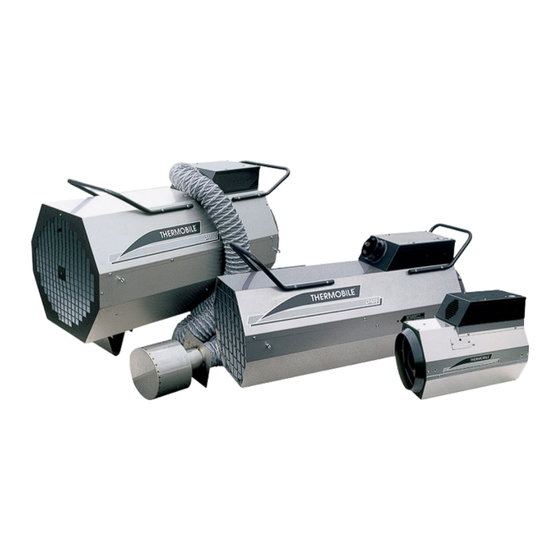
THERMOBILE GA85 Bedienungsanleitung
Vorschau ausblenden Andere Handbücher für GA85:
Inhaltsverzeichnis

Werbung

Verfügbare Sprachen
  • DE

Verfügbare Sprachen

  • DEUTSCH, seite 26
GEBRUIKERSHANDLEIDING
USER MANUAL
BEDIENUNGSANLEITUNG
MANUEL DE L'UTILISATEUR
I
I
инструкция пользователя
MANUAL DEL USUARIO
I
GA42/60/85/110

Werbung

Inhaltsverzeichnis
loading

Inhaltszusammenfassung für THERMOBILE GA85

  • Seite 1 GEBRUIKERSHANDLEIDING USER MANUAL BEDIENUNGSANLEITUNG MANUEL DE L'UTILISATEUR инструкция пользователя MANUAL DEL USUARIO GA42/60/85/110...
  • Seite 2 230V / 50Hz / 0,60Amp. / 0,11 kW IP44 16kg PIN 63AQ4185 SERIE NR: Teller0 F0063 Fabr.year2007 Made by THERMOBILE Industries B.V Breda Holland. AT,FR,IE,LU,BE,GB,NL,DE,CH - 1 - - 2 - I (4x) - 3 - - 4 - - 5 - 40.020.947 - rev.
  • Seite 3 J (4x) - 6 - - 7 - - 8 - - 9 - - 10 - GA 42-60-85-110 40.020.947 - rev. 01 - 2007...
  • Seite 4 GA 110 - 11 - - 12 - 40.020.947 - rev. 01 - 2007 GA 42-60-85-110...
  • Seite 5 Nederlands........6 English ........16 Deutsch ........26 Français ........38 Español ........49 Русский язык......60 GA 42-60-85-110 40.020.947 - rev. 01 - 2007...
  • Seite 6: Inhaltsverzeichnis

    Nederlands Inhoud Milieu Nederlands Veiligheidsinstructies ........7 Let op Introductie ............8 De kachel is gemaakt van diverse Voorbereidingen...........9 metalen en kunststoffen. De kachel Gebruik ............10 bevat tevens elektronische Onderhoud..........10 onderdelen, die als elektronisch afval Storingen............12 moeten worden behandeld. Neem Reserveonderdelen ........15 contact op met uw dealer voor Technische informatie ........15 nadere informatie.
  • Seite 7: Nederlands

    Nederlands VEILIGHEIDSINSTRUCTIES Algemene instructies WAARSCHUWING Pictogrammen in deze handleiding VOORZICHTIG • Lees deze handleiding Wijst op gevaar voor beschadiging zorgvuldig door, alvorens de van de apparatuur. kachel te gebruiken. • Bewaar dit document bij de WAARSCHUWING kachel. Wijst op een gevaarlijke situatie, die •...
  • Seite 8: Introductie

    Nederlands INTRODUCTIE Op de uitgaande zijde van de drukregelaar is een slangbreukbeveiliging gemonteerd, die Doel bij slangbreuk de gastoevoer onderbreekt. Deze kachels zijn direct propaangas De kachel stopt zodra de keuzeschakelaar gestookte kachels met een aansluiting voor op het bedieningspaneel op “0” gezet wordt. een gasfles met drukregelaar.
  • Seite 9: Voorbereidingen

    Nederlands Ionisatiepen VOORBEREIDINGEN Luchttoevoerleiding Ontstekingspen Verpakking verwijderen G Brander 1. Verwijder de verpakking van de kachel. Bedieningspaneel (fig. 7) Installatie Resetknop + controlelamp 1. Zorg voor een stabiele opstelling van de Gasaansluiting kachel. Aansluiting ruimtethermostaat De kachel kan zowel horizontaal als Aansluitsnoer vertikaal (omhoog- of Keuzeschakelaar:...
  • Seite 10: Gebruik

    Nederlands 4. Sluit de andere zijde van de slang aan op ONDERHOUD de gastoevoer van de kachel. 5. Indien de kachel wordt voorzien van een Algemeen ruimtethermostaat, sluit deze aan op de Als de kachel voor langere tijd opgeslagen daarvoor bestemde aansluiting (C) van wordt: het bedieningspaneel, zie fig.
  • Seite 11 Nederlands Beschrijving Periode Iedere Iedere Ieder Ieder week maand half jaar jaar Verwijder stof en aanslag van de kachel. Controleer de kachel (in een schone omgeving). Dealer Controleer de kachel (in een stoffige omgeving). Dealer Controleer en reinig de toevoeropening voor de verbran- dingslucht (GA 60-85-110).
  • Seite 12: Storingen

    Nederlands STORINGEN WAARSCHUWING Neem de netspanningssteker uit de contactdoos en sluit de gastoevoer Zorg dat de netspanning tijdens een reparatie. ingeschakeld is en de gastoevoer geopend is, tijdens het storingzoeken. Verwijder het onderste deel van de buitenmantel (GA42) en het bovenste deel van de buitenmantel (GA 60/85/ 110) voor het plegen van onderhoud aan de inwendige onderdelen.
  • Seite 13 Nederlands Storing Oorzaak Oplossing Actie De kachel gaat in Er is geen of te weing Controleer of de afsluiter op Gebruiker storing: de rode lamp gasdruk voor de mag- de gasfles geopend is. op het bedienings- neetkleppen. Controleer of de gasfles leeg Gebruiker paneel brandt.
  • Seite 14 Nederlands Storing Oorzaak Oplossing Actie De kachel gaat in 13 De maximaalthermos- Vervang de maximaalther- Dealer storing: de rode lamp taat is defect. mostaat. op het bedienings- 14 De ontsteking werkt Controleer de verbinding tus- Gebruiker paneel brandt. niet. sen de trafo en de ontste- kingspen op kortsluiting.
  • Seite 15: Reserveonderdelen

    • Zie voor het elektrische schema het schema C in de annex achterin dit boek. EG-VERKLARING VAN OVEREENSTEMMING Uitleg van het elektrische schema THERMOBILE INDUSTRIES B.V., Konijnenberg 80, NL-4825 BD BREDA, Pos. Description verklaren geheel onder eigen Ionisatiepen verantwoordelijkheid dat de producten:...
  • Seite 16 English Contents Environment English Safety instructions ........17 Note Introduction ..........18 The heater is made of various metals Preparations ..........19 and synthetic materials. The heater Use ............20 also contains electronic parts, which Maintenance ..........20 must be treated as electronic waste. Faults ............21 Please contact your dealer for further Spare parts ..........25 information.
  • Seite 17: Safety Instructions

    English SAFETY INSTRUCTIONS General instructions Warning Pictograms in this manual Caution • Read this manual carefully Indicates risk of damage to the before using the heater. appliance. • Keep this document with the heater. Warning • Follow the described procedures. Indicates a dangerous situation that •...
  • Seite 18: Introduction

    English INTRODUCTION The heater stops when the selector switch on the operating panel is set to “0”. The heater Purpose can be used as a fan by setting the selector These heaters are directly propane gas-fired switch on the operating panel to position 2. heaters with a connection for a gas bottle with pressure controller.
  • Seite 19: Accessories

    English Operating panel (fig. 7) PREPARATIONS Reset button + indicator Gas connection Remove packaging Connection point for room thermostat 1. Remove packaging from the heater. Connection cable Selector switch: Installation 0 = Off 1. Make sure that the heater has a stable set-up.
  • Seite 20: Use

    English 5. If the heater is provided with a room MAINTENANCE thermostat, connect this to the appropriate connection (C) of the General operating panel, see fig. 7. This For long-term storage of the heater: connection has as a rule been provided 1.
  • Seite 21: Faults

    English Description Period Weekl Monthl Every Annu- ally month Remove dust and deposits from the heater. Check the heater (in a clean environment). Dealer Check the heater (in a dusty environment). Dealer Check and clean the supply opening for the combustion air (GA 60-85-110).
  • Seite 22: Troubleshooting Table

    English Warning Remove the mains plug from the socket and shut off the gas supply during repair. Troubleshooting table Fault Cause Solution Action The heater does not The heater has no volt- Check the electrical connec- User start up. age. tion.
  • Seite 23 English Fault Cause Solution Action The heater has a There is no or not Check if the shut-off valve on User fault: the red lamp on enough gas pressure for the gas bottle is open. the operating panel the magnet valves. Check if the gas bottle is User lights up.
  • Seite 24 English Fault Cause Solution Action The heater has a 13 The maximum thermo- Replace the maximum ther- Dealer fault: the red lamp on stat is defective. mostat. the operating panel 14 The ignition is not func- Check the connection User lights up.
  • Seite 25: Spare Parts

    100 mm. diagram C in the annex at the back of this manual. EU DECLARATION OF CONFORMITY Explanation of the electrical circuit THERMOBILE INDUSTRIES B.V., diagram Konijnenberg 80, NL-4825 BD BREDA, assume full responsibility when declaring that Pos. Description...
  • Seite 26 Deutsch Inhalt Garantie und Haftung Deutsch Sicherheitshinweise ........27 Die Bestimmungen in Bezug auf die Garantie Einführung ..........28 und Haftung finden Sie unter den Vorbereitungen ..........30 allgemeinen Garantiebedingungen. Verwendung..........31 Wartung .............31 Umweltschutzbestimmungen Störungen ..........32 Hinweis Ersatzteile ..........36 Der Heizer besteht aus Technische Informationen......36 verschiedenen Metallen und Installation von Zubehör ......36...
  • Seite 27: Sicherheitshinweise

    Deutsch SICHERHEITSHINWEISE • Auftauen von Leitungen, Anlagen, Geräten und Gütern in NICHT Piktogramme in dieser brandgefährlichen Situationen Betriebsanleitung • Frostüberwachung in der Industrie, auf dem Bau und in Polytunneln im Vorsicht Gartenbau. Gefahr einer Produktbeschädigung Achtung Gefährliche Situationen, die den Tod oder ernsthafte Verletzungen zur Folge haben können.
  • Seite 28: Allgemeine Anweisungen

    Deutsch Allgemeine Anweisungen EINFÜHRUNG Achtung Ziel Diese Heizer werden direkt mit Propangas • Lesen Sie zunächst dieses befeuert und sind mit einem Anschluss für Handbuch aufmerksam durch, eine Gasflasche mit Druckregler versehen. bevor Sie den Heizer zum Die Heizer sind mit einem Warmluftventilator Einsatz bringen.
  • Seite 29 Deutsch Bei einer Störung schaltet der automatische Hauptkomponenten Brennkammer Brenner den Heizer aus. In diesem Fall GA 60-85-110 (Abb. 5) leuchtet eine rote Lampe auf dem Bedienpult. Brennkammer An der Ausgangsseite des Druckreglers ist Gaszufuhrleitung eine Schlauchbruchsicherung montiert, die Zerstäuber bei einem Schlauchbruch die Gaszufuhr Ionisationsstift unterbricht.
  • Seite 30: Vorbereitungen

    Deutsch VORBEREITUNGEN Achtung Verpackung entfernen 1. Entfernen Sie die Verpackung des • Schließen Sie den Heizer Heizers. ausschließlich mit dem mitgelieferten Schlauch mit Installation Druckregler und 1. Sorgen Sie für eine stabile Aufstellung Schlauchbruchsicherung an die des Heizers. Gasflasche an. Der Heizer kann sowohl horizontal •...
  • Seite 31: Verwendung

    Deutsch Starten WARTUNG Erwärmen: 1. Öffnen Sie das Ventil auf der Gaszufuhr. Allgemein 2. Drücken Sie auf den Knopf der Falls der Heizer für längere Zeit gelagert Schlauchbruchsicherung. wird: 3. Schalten Sie den Wahlschalter (Abb. 7E) 1. Schalten Sie den Heizer aus. auf die Position 1.
  • Seite 32: Störungen

    Deutsch Beschreibung Periode Wöche Monat- Alle Jähr- ntlich lich halbe lich Jahre Das Einlassgitter kontrollieren und reinigen. Den Warmluftventilator auf Funktion und Beschädigungen hin kontrollieren. Den Heizer auf eine korrekte Verbrennung hin kontrollie- ren. Die Flamme muss blau sein. Wenn die Flamme gelb ist, wenden Sie sich bitte an Ihren Händler.
  • Seite 33 Deutsch Tabelle Störungssuche Störung Ursache Lösung Hand- lung Der Heizer läuft nicht Der Heizer hat keine Kontrollieren Sie den elektri- Benutzer Spannung. schen Anschluss. Der Ventilatormotor Stellen Sie sicher, dass der Benutzer dreht sich schwer oder Ventilatormotor nicht ver- wird blockiert. schmutzt ist oder blockiert wird.
  • Seite 34 Deutsch Störung Ursache Lösung Hand- lung Der Heizer schaltet Die Magnetventile öff- Drücken Sie auf den Reset- Benutzer auf Störung: Die rote nen sich nicht. knopf des Maximalthermos- Lampe auf dem tats und des Bedienpults. Bedienpult leuchtet. Kontrollieren Sie den Maxi- Händler malthermostat.
  • Seite 35 Deutsch Störung Ursache Lösung Hand- lung 14 Die Zündung funktioniert Kontrollieren Sie die Verbin- Benutzer nicht. dung zwischen dem Trafo und dem Zündstift auf Kurz- schluss hin. Kontrollieren Sie die Einstel- Benutzer lung des Zündstifts (siehe unter “Einstellen Zündstift”). Die Gaszufuhr wird 15 Der Thermostat ist auf Korrigieren Sie die Einstel- Benutzer...
  • Seite 36: Ersatzteile

    Deutsch Störung Ursache Lösung Hand- lung Der Heizer kann mit 20 Die Magnetventile Schließen Sie die Gaszufuhr Benutzer diesem Schalter schließen nicht oder der und lassen Sie die Flamme nicht ausgeschaltet Schalter ist defekt. ausbrennen. werden. Unterbrechen Sie den Netz- Benutzer anschluss.
  • Seite 37: Eg-Konformitätserklärung

    Deutsch EG-KONFORMITÄTSERKLÄRUNG THERMOBILE INDUSTRIES B.V., Konijnenberg 80, NL-4825 BD BREDA, erklären in eigener Verantwortung, dass die Produkte: PROPANGAS BEFEUERTE LUFTERHITZER GA 42, GA 60, GA 85 und GA 110 den nachstehenden EG-Richtlinien genügen: Maschinenrichtlinie: 98/37/EEC Niederspannungsrichtlinie: 72/23/EEC EMC-Richtlinie: 89/336/EEC Niederlande, Breda, 01-05-2005 R.E.
  • Seite 38 Français Table des matières Pour la garantie et la responsabilité, voir les Français Consignes de sécurité .......39 conditions générales de garantie. Introduction ..........40 Préparations ..........41 Environnement Emploi............42 Remarque Entretien ............42 Le générateur se compose de Pannes............44 plusieurs métaux et plastiques. Pièces de rechange ........47 Il contient également des Renseignements techniques .....47...
  • Seite 39: Consignes De Sécurité

    Français CONSIGNES DE SÉCURITÉ • Dégivrage de conduites, installations, appareils et marchandises se trouvant Pictogrammes dans ce manuel dans des conditions à l’abri des risques de feu. Précaution • Contrôle de gel dans l’industrie, la Signifie le risque d'endommagement construction et les tunnels horticoles. de l'appareil.
  • Seite 40: Introduction

    Français INTRODUCTION En cas de panne, le brûleur automatique éteint l’appareil de chauffage. De plus, le voyant lumineux rouge situé sur le panneau Ces appareils de chauffage sont des de commande s’allume. appareils à combustion directe de propane, À la sortie du régulateur de pression est munis d’un dispositif de raccordement pour monté...
  • Seite 41: Préparations

    Français Tuyau d’arrivée de gaz PRÉPARATIONS Gicleur Électrode d’allumage Enlever l'emballage G Thermostat à réinitialisation automatique 1. Enlever l'emballage de l’appareil de chauffage. Principaux composants de la chambre de combustion GA 60-85- Installation 110 (fig. 5) 1. Assurer une installation stable de Chambre de combustion l’appareil de chauffage.
  • Seite 42: Emploi

    Français 3. Raccorder à la bouteille de gaz le flexible EMPLOI à gaz fourni avec le régulateur de pression (A) et le dispositif de sécurité à Pendant le service rupture de flexible (B) ; pour le modèle Chaud GA 42 voir fig. 8, pour le modèle GA 60- Ne pas toucher la cheminée et la 85-110, voir fig.
  • Seite 43 Français Désignation Période Cha- Cha- Cha- Cha- semai mois semes année Enlever la poussière et le tartre de l’appareil de chauffage. X Contrôler l’appareil de chauffage (dans un environnement Con- propre). ces- sionnai Contrôler l’appareil de chauffage (dans un environnement Con- poussiéreux).
  • Seite 44: Pannes

    Français Réglage de l’électrode d’allumage PANNES 1. Retirer la grille de la bouche de soufflage (GA 60-85-110). L’électrode d’allumage Pendant la recherche de panne, est accessible par la bouche de s’assurer que l’alimentation soufflage. électrique fonctionne et que l’arrivée 2. Contrôler la distance entre l’électrode de gaz est ouverte.
  • Seite 45 Français Panne Cause Remède Action L’appareil de chauf- La fiche secteur est Retourner la fiche. Utilisateur fage tombe en panne; mal positionnée dans le voyant lumineux la prise de courant. rouge sur le panneau La terre de la prise de Faire contrôler la terre de la Utilisateur de commande est...
  • Seite 46 Français Panne Cause Remède Action L’appareil de chauf- Le thermostat maxi- Contrôler la grille d’aspiration Utilisateur fage tombe en panne : mum a été mis hors et la bouche de soufflage La lampe rouge sur le service quant à la présence de panneau de com- saleté...
  • Seite 47: Pièces De Rechange

    Français Panne Cause Remède Action L’arrivée de gaz est Le thermostat est Corriger le réglage. Utilisateur interrompue pendant réglé à une tempéra- le fonctionnement de ture trop basse. l’appareil et la flamme Défaillance dans le Réparer ou remplacer le pan- Conces- s’éteint.
  • Seite 48: Installation Des Accessoires

    Français Explication du schéma électrique DÉCLARATION DE CONFORMITÉ Pos. Description THERMOBILE INDUSTRIES B.V., Électrode d’ionisation Konijnenberg 80, NL-4825 BD BREDA, Électrode d’allumage affirme entièrement sous son propre Transformateur d’allumage responsabilité que les produits: Thermostat maximum APPAREILS DE CHAUFFAGE D’AIR À...
  • Seite 49 Español Índice Consulte los términos de garantía y Español Instrucciones de seguridad ....... 50 responsabilidad en las reglas generales de Introducción ..........51 garantía. Preparaciones ........... 52 Uso............53 Medio ambiente Mantenimiento .......... 53 Nota Fallos ............55 El generador de aire caliente está Piezas de repuesto ........
  • Seite 50: Español

    Español INSTRUCCIONES DE SEGURIDAD • La descongelación de tuberías, instalaciones, aparatos y mercancías en Símbolos utilizados en este situaciones donde no haya peligro de manual incendio. • Protección antihielo en la industria, la Precaución construcción y túneles en horticultura. Indica un riesgo de daños en el aparato.
  • Seite 51: Introducción

    Español INTRODUCCIÓN En caso de fallo, el mecanismo de automatización del quemador desconectará Propósito el generador. Ahora se enciende la luz roja Estos generadores de aire caliente son del panel de manejo. generadores de combustión directa de gas En el lado de salida del controlador de propano con una conexión para una presión se ha montado una protección de bombona de gas con controlador de presión.
  • Seite 52: Preparaciones

    Español Electrodo de ionización PREPARACIONES Conducto de suministro de gas Boquilla Desembalaje Electrodo de encendido 1. Retire el embalaje del generador. G Termostato con restablecimiento automático Instalación 1. Asegúrese de que el generador tenga Componentes principales de la una base estable. cámara de combustión GA 60-85- El generador puede colocarse 110 (fig.
  • Seite 53: Puesta En Marcha

    Español 3. Conecte la manguera de gas suministrada con el controlador de presión (A) y la protección de ruptura de Durante el funcionamiento manguera (B) a la bombona de gas, para Caliente GA 42 véase la fig. 8, para GA 60-85-110 ¡No toque la chimenea ni las véase la fig.
  • Seite 54 Español Descripción Período Sema- Men- Semes Anual sual tral Retire el polvo y los depósitos del generador. Compruebe el generador (en un entorno limpio). Distri- buidor Compruebe el generador (en un entorno con polvo). Distri- buidor Compruebe y limpie la abertura de suministro del aire de combustión (GA 60-85-110).
  • Seite 55: Fallos

    Español FALLOS Advertencia Retire el enchufe de red de la toma y cierre el suministro de gas durante la Durante la localización de averías, reparación. asegúrese de que la tensión de red esté conectada y que el suministro de gas esté abierto. Retire la parte inferior de la carcasa exterior (GA42) y la parte superior de la carcasa exterior (GA 60/85/110)
  • Seite 56 Español Fallo Causa Solución Acción El generador genera No hay (o no hay sufi- Compruebe si la válvula de Usuario un fallo: la luz roja ciente) presión de gas corte de la bombona de gas del panel de manejo para las válvulas elec- está...
  • Seite 57 Español Fallo Causa Solución Acción El generador genera 13 El termostato máximo Sustituya el termostato Distribui- un fallo: la luz roja está defectuoso. máximo. del panel de manejo 14 El encendido no fun- Compruebe la conexión Usuario se enciende. ciona. entre el transformador y el electrodo de encendido para ver si hay un cortocircuito.
  • Seite 58: Piezas De Repuesto

    Español Fallo Causa Solución Acción El generador no 20 Las válvulas electro- Cierre el suministro de gas y Usuario puede desconec- magnéticas no se cie- deje que la llama se extinga. tarse con el interrup- rran o el interruptor está Desconecte la conexión de Usuario tor.
  • Seite 59: Declaración Ce De Conformidad

    Español DECLARACIÓN CE DE CONFORMIDAD THERMOBILE INDUSTRIES B.V., Konijnenberg 80, NL-4825 BD BREDA, asume plena responsabilidad al declarar que los productos: GENERADORES DE AIRE CALIENTE DE GAS PROPANO GA 42, GA 60, GA 85 y GA cumplen con las siguientes directivas CE: Directiva sobre maquinaria: 98/37/CEE Directiva de baja tensión: 72/23/CEE...
  • Seite 60 PУССКИЙ џЗЫК Содержание Гарантия и ответственность Русский язык Инструкции по технике безопасности..61 По вопросам гарантии и ответственности Введение ..........62 см. общие гарантийные условия. Подготовка к работе.........64 Эксплуатация ...........65 Окружающая среда Техническое обслуживание.....65 Примечание Неисправности .........66 Нагреватель сделан из различных Запасные части ........70 металлов...
  • Seite 61: Инструкции По Технике Безопасности

    pусский язык Инструкции по технике Нагрева помещений с серьезной • вентиляцией. безопасности Размораживания труб, установок, • устройств и товаров в тех случаях, Пиктограммы в данном когда отсутствует опасность руководстве возгорания. ВНИМАНИЕ Для защиты от замораживания в • Указывает на опасность промышленности, строительстве, повреждения...
  • Seite 62: Общие Указания

    PУССКИЙ џЗЫК Введение Общие указания ОСТОРОЖНО Назначение Данные нагреватели являются газовыми Внимательно прочитайте • нагревателями прямого нагрева, газовый данное руководство перед баллон подключается с использованием началом использования регулятора давления. воздухонагревателя. Воздухонагреватели оборудованы Храните данный документ • вентилятором горячего воздуха и вместе...
  • Seite 63 pусский язык ограничительный термостат. Его можно Основные элементы камеры вручную переустановить после сгорания GA 42 (рис. 4) охлаждения (только для GA 42). Камера сгорания В случае отказа автомат горелки Горелка отключает воздухонагреватель. При этом Электрод ионизации загорается красная лампочка на панели Линия...
  • Seite 64: Подготовка К Работе

    PУССКИЙ џЗЫК Подготовка к работе 3. Подключите шланг подачи газа с регулятором давления (А) и системой защиты шланга (В) к газовому баллону, Распаковка для GA 42 см. рис. 8, для GA 60-85-110 1. Распакуйте нагреватель. см. рис. 9. 4. Подсоедините внешнюю сторону Монтаж...
  • Seite 65: Эксплуатация

    pусский язык Эксплуатация 3. Выньте контактную вилку из гнезда питания. 4. Произведите чистку нагревателя. Во время работы Горячо! Таблица техобслуживания Не прикасайтесь к дымоходу и После каждого зимнего сезона выходным отверстиям! регистрируйте проведение техосмотра в Во время работы устройства они таблице, которая...
  • Seite 66: Неисправности

    PУССКИЙ џЗЫК Описание Период Ежене Ежеме Кажды Ежего дельн сячно е дно о шесть месяц ев Произведите чистку форсуночной головки при помощи металлической щетки и сжатого воздуха. Почистите жиклёр и входное отверстие. Произведите чистку электрода ионизации и электрода зажигания с помощью стальной ваты. Проверьте...
  • Seite 67: Таблица Поиска Неисправностей

    pусский язык Таблица поиска неисправностей Неисправность Причина Устранение Действи е Воздухонагревател Не подается Проверьте подачу Пользова ь не включается. напряжение. электроэнергии. тель Двигатель Проверьте, возможно Пользова вентилятора тяжело двигатель вентилятора тель движется или вообще засорен или застопорен. не работает. Замените двигатель Дилер...
  • Seite 68 PУССКИЙ џЗЫК Неисправность Причина Устранение Действи е Нагреватель В в магнитных Закройте отсечной клапан Пользова неисправен: клапанах низкое подачи газа газового тель загорается красная давление газа, либо баллона. лампочка на панели давление отсутствует. Проверьте, возможно Пользова управления. газовый баллон пуст. тель...
  • Seite 69 pусский язык Неисправность Причина Устранение Действи е Нагреватель 13 Термостат верхнего Замените ограничительный Дилер неисправен: предела неисправен. термостат. загорается красная 14 Зажигание не Проверьте, возможно Пользова лампочка на панели работает. произошло короткое тель управления. замыкание между трансформатором и электродом зажигания. Проверьте...
  • Seite 70: Запасные Части

    PУССКИЙ џЗЫК Неисправность Причина Устранение Действи е Воздухонагревател 20 Магнитные клапаны не Отключите подачу газа и Пользова ь не выключается с закрыты или дайте пламени погаснуть. тель помощью поврежден Отключите подачу Пользова выключателя. выключатель. электроэнергии. тель Проверьте магнитные Дилер клапаны и выключатель, при...
  • Seite 71: Eс-Декларация Соответствия

    язык EС-Декларация соответствия THERMOBILE INDUSTRIES B.V., Konijnenberg 80, NL-4825 BD BREDA с полной ответственностью заявляет, что изделия: ПРОПАНОВЫЕ ГАЗОВЫЕ ВОЗДУХОНАГРЕВАТЕЛИ GA 42, GA 60, GA 85 и GA 110 соответствуют следующим директивам ЕС: Нормативам по машиностроению: 98/37/ Нормативам по низкому напряжению: 72/ 23/EEC ЕМС-нормативам: 89/336/EEC...
  • Seite 72 Datum Omschrijving: Onderhoud of Storing Actie door Date Description: Maintenance or Failure Action by Datum Beschreibung: Wartung oder Fehler Aktion durch Date Description: Entretien ou Erreur Action par Fecha Descripcíon Mantenimiento o fallo Accíon por Дата Описание: устранение неисправности Выполнено 40.020.947 - rev.
  • Seite 73 Datum Omschrijving: Onderhoud of Storing Actie door Date Description: Maintenance or Failure Action by Datum Beschreibung: Wartung oder Fehler Aktion durch Date Description: Entretien ou Erreur Action par Fecha Descripcíon Mantenimiento o fallo Accíon por Дата Описание: устранение неисправности Выполнено GA 42-60-85-110 40.020.947 - rev.
  • Seite 74 Datum Omschrijving: Onderhoud of Storing Actie door Date Description: Maintenance or Failure Action by Datum Beschreibung: Wartung oder Fehler Aktion durch Date Description: Entretien ou Erreur Action par Fecha Descripcíon Mantenimiento o fallo Accíon por Дата Описание: устранение неисправности Выполнено 40.020.947 - rev.
  • Seite 75 Datum Omschrijving: Onderhoud of Storing Actie door Date Description: Maintenance or Failure Action by Datum Beschreibung: Wartung oder Fehler Aktion durch Date Description: Entretien ou Erreur Action par Fecha Descripcíon Mantenimiento o fallo Accíon por Дата Описание: устранение неисправности Выполнено GA 42-60-85-110 40.020.947 - rev.
  • Seite 76 GA 42 GA 60 GA 85 GA 110 Capaciteit Hs MJ / h 50 - 158 97 - 230 140 -335 194 - 468 Heat output max. Hs 14 - 44 27 - 64 39 -93 54 - 130 Wärmeleistung Hs Pouvoir thermique max.
  • Seite 77 GA 42 GA 60 GA 85 GA 110 Verstuiver Nozzle Düse Gliceur Boquilla Сопло Aansluitwaarde V/Hz 230 / 50 230 / 50 230 / 50 230 / 50 Supply voltage Versorgungsspannung Tension d’alimentation Tensión de suministro Напряжение источника питания Max. stroomverbruik Amp.
  • Seite 78 GA 42 GA 60 GA 85 GA 110 Brandstofverbruik Zie grafiek / See diagram / Sehe Grafik / Voir graphique / Ver grafico / см. схем Fuel consumption Brennstoffverbrauch Consommation de combustible Consumo de combustible Расход топлива Lengte Length Länge Longeur Longitud Длина...
  • Seite 79 Voorbeeld Example GA 42 Example Ejemplo Пример Beispiel Drukinstelling Pression 0.7 bar Pressure Presion Давление Druckeinstellung Capaciteit Capacité 26 kW Capacity Capacidad Объем Kapazität Verbruik Consommation 1.9 kg / h Consumption Consumo Потребление Verbrauch MJ/h MJ/h GA 42 GA 60 MJ/h MJ/h 180 194...
  • Seite 80 C: GA 42 40.020.947 - rev. 01 - 2007 GA 42-60-85-110...
  • Seite 81 GA 60 - 85 - 110 GA 42-60-85-110 40.020.947 - rev. 01 - 2007...
  • Seite 82 40.020.947 - rev. 01 - 2007 GA 42-60-85-110...
  • Seite 83 All rights reserved. The available information has been prepared to a high level of care, but Thermobile Industries B.V. cannot be held liable for possible errors in the information or the consequences thereof. The information provided herein may not be reproduced and/or published in any form, by print, (electronically or mechanically) without the prior written authorisation of Thermobile Industries B.V.

Diese Anleitung auch für:

Ga60Ga110

Inhaltsverzeichnis