Herunterladen Inhalt Inhalt Diese Seite drucken
Franke FGB 906 IS AC Bedienungsanleitung Und Einrichtung

Franke FGB 906 IS AC Bedienungsanleitung Und Einrichtung

Vorschau ausblenden Andere Handbücher für FGB 906 IS AC:

Werbung

Verfügbare Sprachen
  • DE

Verfügbare Sprachen

Instructions for use and installation
GB
Cooker Hood
Istruzioni per l'uso e l'installazione
IT
Cappa
Mode d'emploi et installation
FR
Hotte de Cuisine
Bedienungsanleitung und Einrichtung
DE
Dunstabzugshaube
Kullanım ve montaj talimatları
TR
Davlumbaz
FGB 906 IS AC

Werbung

Inhaltsverzeichnis
loading

Inhaltszusammenfassung für Franke FGB 906 IS AC

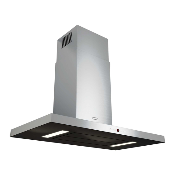
  • Seite 1 Instructions for use and installation Cooker Hood Istruzioni per l’uso e l’installazione Cappa Mode d’emploi et installation Hotte de Cuisine Bedienungsanleitung und Einrichtung Dunstabzugshaube Kullanım ve montaj talimatları Davlumbaz FGB 906 IS AC...
  • Seite 2: Inhaltsverzeichnis

    INDEX RECOMMENDATIONS AND SUGGESTIONS ........................3 CHARACTERISTICS ................................4 INSTALLATION..................................6 USE ...................................... 10 MAINTENANCE ................................... 12 INDICE CONSIGLI E SUGGERIMENTI............................14 CARATTERISTICHE................................15 INSTALLAZIONE ................................. 17 USO...................................... 21 MANUTENZIONE ................................23 SOMMAIRE CONSEILS ET SUGGESTIONS............................25 CARACTERISTIQUES................................. 26 INSTALLATION..................................28 UTILISATION ..................................
  • Seite 3: Recommendations And Suggestions

    RECOMMENDATIONS AND SUGGESTIONS The Instructions for Use apply to several versions of this appliance. Accordingly, you may find descriptions of individual features that do not apply to your specific appliance. INSTALLATION • The manufacturer will not be held liable for any damages resulting from incorrect or improper installation.
  • Seite 4 CHARACTERISTICS Dimensions...
  • Seite 5 Components Ref. Q.ty Product Components Hood Canopy complete with: Controls, Light, Filters Telescopic chimney, made up of: Upper chimney Lower chimney Telescopic frame complete with Suction fan, made up 7.1a Upper frame 7.1b Lower frame Reduction flange ø 150-120 mm 14.1 Air Outlet Connector Extension Air Outlet Connector...
  • Seite 6 INSTALLATION Drilling the Ceiling/shelf and fixing the frame DRILLING THE CEILING/SHELF • Use a plumb line to mark the centre of the hob on the ceiling/support shelf. • Place the drilling template 21 provided on the ceiling/support shelf, making sure that the template is in the correct position by lining up the axes of the template with those of the hob.
  • Seite 7 Fixing the frame • Loosen the two screws fastening the lower chimney and re- move this from the lower frame. • Loosen the two screws fastening the upper chimney and re- move this from the upper frame. If you wish to adjust the height of the frame, proceed as follows: •...
  • Seite 8 Connections DUCTED VERSION AIR EXHAUST SYSTEM ø 150 ø 120 When installing the ducted version, connect the hood to the chimney using either a flexible or rigid pipe ø 150 or 120 mm, the choice of which is left to the installer. •...
  • Seite 9: Electrical Connection

    Flue assembly - Mounting the hood body • Position the upper chimney section and fix the upper part to the frame using the 2 screws 12c (2,9 x 6,5) provided. • Similarly, position the lower chimney section and fix the lower part to the frame using the 2 screws 12c (2,9 x 6,5) pro- vided.
  • Seite 10: Control Panel

    Control panel Button Function Display Turns the suction motor on and off at speed one. Displays the set speed Decreases the working speed. Displays the set speed Increases the working speed. Displays the set speed Activates Intensive speed from any other speed, Displays HI and the time remaining alternately, once a including motor off.
  • Seite 11: Remote Control Panel

    REMOTE CONTROL (OPTIONAL) The appliance can be controlled using a remote control powered by a 1.5 V carbon-zinc alkaline batteries of the standard LR03-AAA type (not included). • Do not place the remote control near to heat sources. • Used batteries must be disposed of in the proper manner.
  • Seite 12 MAINTENANCE Opening Panel • Open the Panel by pulling it. • Clean the outside with a damp cloth and neutral detergent. • Clean the inside using a damp cloth and neutral detergent; do not use wet cloths or sponges, or jets of water; do not use abrasive substances.
  • Seite 13 Activated Charcoal Filter (Recirculation Version) It cannot be washed or regenerated, and must be changed when the FC symbol on the display appears, or at least once every 4 months. The Alarm signal, if it has been activated, only appears when the Suction motor is turned on. Activating the alarm signal •...
  • Seite 14: Consigli E Suggerimenti

    CONSIGLI E SUGGERIMENTI Questo libretto di istruzioni per l' u so è previsto per più versioni dell' apparecchio. É possibile che siano descritti singoli particolari della dotazione, che non riguardano il Vostro apparecchio. INSTALLAZIONE • Il produttore declina qualsiasi responsabilità per danni dovuti ad installazione non corretta o non conforme alle regole dell’arte.
  • Seite 15: Caratteristiche

    CARATTERISTICHE Ingombro 1 15...
  • Seite 16 Componenti Rif. Q.tà Componenti di Prodotto Corpo Cappa completo di: Comandi, Luce, Filtri Camino telescopico formato da: Camino superiore Camino inferiore Traliccio telescopico completo di Aspiratore, formato 7.1a Traliccio superiore 7.1b Traliccio inferiore Flangia di riduzione ø 150-120 mm 14.1 Prolunga Raccordo Uscita Aria Raccordo Uscita Aria Fascette stringitubo (non incluse)
  • Seite 17 INSTALLAZIONE Foratura Soffitto/Mensola e Fissaggio Traliccio FORATURA SOFFITTO/MENSOLA • Con l’ausilio di un Filo a piombo riportare sul Soffitto/Mensola di supporto il centro del Piano di Cottura. • Appoggiare al Soffitto/Mensola la Dima di Foratura 21 in dotazione, facendo coincidere il suo centro al centro proiettato e allineando gli assi della Dima agli assi del Piano di Cottura.
  • Seite 18 Fissaggio Traliccio • Svitare le due viti che fissano il camino inferiore e sfilarlo dal traliccio (dalla parte inferiore). • Svitare le due viti che fissano il camino superiore e sfilarlo dal traliccio (dalla parte superiore). Nel caso in cui si voglia regolare l’altezza del traliccio procedere come segue: •...
  • Seite 19 Connessioni USCITA ARIA VERSIONE ASPIRANTE ø 150 Per installazione in Versione Aspirante collegare la Cappa alla ø 120 tubazione di uscita per mezzo di un tubo rigido o flessibile di ø150 o 120 mm, la cui scelta è lasciata all'installatore. •...
  • Seite 20: Connessione Elettrica

    Montaggio Camino e Fissaggio Corpo Cappa • Posizionare il Camino superiore e fissare nella parte superiore al Traliccio con 2 Viti 12c (2,9 x 6,5) in dotazione. • Analogamente posizionare il Camino inferiore e fissare nella parte inferiore al Traliccio con 2 Viti 12c (2,9 x 6,5) in dota- zione.
  • Seite 21: Quadro Comandi

    Quadro comandi Tasto Funzione Display Accende e spegne il motore di aspirazione alla prima Visualizza la velocità impostata velocità. Decrementa la velocità di esercizio. Visualizza la velocità impostata Incrementa la velocità di esercizio. Visualizza la velocità impostata Attiva la velocità Intensiva da qualsiasi velocità Visualizza alternamente HI e il tempo rimanente una anche da motore spento, tale velocità...
  • Seite 22: Telecomando (Opzionale)

    TELECOMANDO (OPZIONALE) Questo apparecchio può essere comandato per mezzo di un telecomando, alimentato con pile alcaline zinco- carbone da 1,5 V del tipo standard LR03-AAA (non incluse). • Non riporre il telecomando in prossimità di fonti di calore. • Non disperdere le pile nell’ambiente, depositarle ne- gli appositi contenitori.
  • Seite 23: Pulizia Filtri

    MANUTENZIONE Apertura Pannello • Aprire il Pannello tirandolo. • Pulirlo esternamente con un panno umido e detersivo liquido neutro. • Pulirlo anche internamente utilizzando un panno umido e de- tergente neutro; non utilizzare panni o spugne bagnate, né getti d’acqua; non utilizzare sostanze abrasive. Filtri antigrasso metallici Sono lavabili anche in lavastoviglie, e necessitano di essere lavati quando sul display appare FG o almeno ogni 2 mesi circa di uti-...
  • Seite 24 Filtri antiodore al Carbone attivo (Versione Filtrante) Non è lavabile e non è rigenerabile, va sostituito quando sul display appare FC o almeno ogni 4 mesi. La segnalazione di Allarme, se preventivamente attivata, si verifica solo quando è a- zionato il Motore di aspirazione. Attivazione del segnale di allarme •...
  • Seite 25: Conseils Et Suggestions

    CONSEILS ET SUGGESTIONS La présente notice d' e mploi vaut pour plusieurs versions de l' a ppareil. Elle peut contenir des descriptions d' a c- cessoires ne figurant pas dans votre appareil. INSTALLATION • Le fabricant décline toute responsabilité en cas de dommage dû à une installation non correcte ou non conforme aux règles de l’art.
  • Seite 26: Caracteristiques

    CARACTERISTIQUES Encombrement 2 26...
  • Seite 27 Composants Réf. Q.té Composants de Produit Corps Hotte équipé de: Comandes, Lumière, Filtres Cheminée Télescopique formée de : Cheminée Supérieure Cheminée Inférieure Treillis télescopique avec Aspirateur, formé par: 7.1a Treillis supérieur 7.1b Treillis inférieur Flasque de Réduction ø 150-120 mm 14.1 Rallonge Raccord Sortie Air Raccord Sortie Air...
  • Seite 28: Installation

    INSTALLATION Perçage Plafond/Étagère et Fixation Treillis PERÇAGE PLAFOND/ETAGERE • À l’aide d’un Fil à plomb, reporter sur le Plafond/Étagère de support le centre du Plan de Cuisson. • Poser contre le Plafond/Étagère le Gabarit de Perçage 21 fourni avec l’appareil, en faisant coïncider son centre avec le centre projeté...
  • Seite 29 FiXATION TREILLIS • Dévisser les deux vis qui fixent la cheminée inférieure et sortir cette dernière du treillis (depuis la partie inférieure). • Dévisser les deux vis qui fixent la cheminée supérieure et sortir cette dernière du treillis (depuis la partie supérieure). Si l’on souhaite régler la hauteur du treillis, effectuer les opéra- tions suivantes: •...
  • Seite 30 Branchements SORTIE AIR VERSION ASPIRANTE ø 150 En cas d’installation en version aspirante, brancher la hotte à la ø 120 tuyauterie de sortie via un tube rigide ou flexible de ø 150 ou 120 mm, au choix de l’installateur. • En cas de branchement avec un tube de ø120 mm, insérer le flasque de réduction 9 sur la sortie du corps de la hotte.
  • Seite 31: Branchement Electrique

    Montage Cheminée - Montage Corps Hotte • Positionner la Cheminée supérieure et fixer cette dernière dans la partie supérieure du Treillis à l’aide de 2 Vis 12c (2,9 x 6,5) fournies avec l’appareil. • De la même façon, positionner la Cheminée inférieure et fixer cette dernière dans la partie inférieure du Treillis à...
  • Seite 32: Utilisation

    UTILISATION Tableau commandes Touche Fonction Affichage Branche et débranche le moteur d’aspiration à la première Affiche la vitesse paramétrée vitesse. Diminue la vitesse d’exercice. Affiche la vitesse paramétrée Augmente la vitesse d’exercice. Affiche la vitesse paramétrée Active la vitesse Intensive depuis n’importe quelle vitesse, Affiche alternativement HI et le temps restant une fois par même à...
  • Seite 33 TELECOMMANDE (FOURNIE SUR DEMANDE) Il est possible de commander cet appareil au moyen d’une télécommande, alimentée avec des piles alcalines zinc-charbon 1,5 V du type standard LR03-AAA (non compris). • Ne pas ranger la télécommande à proximité de sour- ces de chaleur. •...
  • Seite 34: Entretien

    ENTRETIEN Ouverture panneau • Ouvrir le panneau en le tirant. • Le nettoyer à l’extérieur avec un chiffon humide et un détergent liquide neutre. • Le nettoyer également à l’intérieur avec un chiffon humide et un détergent neutre ; ne jamais utiliser des chiffons ou des éponges mouillés, ni des jets d’eau ;...
  • Seite 35 Filtres anti-odeur au charbon actif (version filtrante) Non lavable et non régénérable, il doit être remplacé à l’affichage de FC ou au moins tous les 4 mois. Le signal d’alarme, si préalablement activé, a lieu seulement lorsque le moteur d’aspiration est en marche. Activation du signal d’alarme •...
  • Seite 36: Empfehlungen Und Hinweise

    EMPFEHLUNGEN UND HINWEISE Di e se Gebrauchsanl e i t ung gi l t für mehrere Geräte-Ausführungen. Es i s t mögl i c h, dass ei n zel n e Ausstattungsmerk- mal e beschri e ben si n d, di e ni c ht auf Ihr Gerät zutreffen. MONTAGE •...
  • Seite 37: Charakteristiken

    CHARAKTERISTIKEN Platzbedarf 3 37...
  • Seite 38 Komponenten Pos. Produktkomponenten Haubenkörper mit Schaltern, Teleskopkamin bestehend aus: oberer Kaminteil unterer Kaminteil Teleskopgerüst komplett mit Gebläse, bestehend aus: 7.1a oberer Gerüstteil 7.1b unterer Gerüstteil Reduzierflansch ø 150-120 mm 14.1 Verlängerung Luftaustritt-Anschlussstück Luftaustritt-Anschlussstück Rohrschellen (nicht enthalten) Pos. Montagekomponenten Bügel für Anschlusshalter Bügel ø...
  • Seite 39: Montage

    MONTAGE Bohren der Decke/Trägerplatte und Montage des Teleskopgerüsts Achtung: Bitte beachten Sie bei der Montage das Gewicht der kompletten Haube. Die Tragfä- higkeit der Decke oder alternativ der Trägerplatte für diese Zugbelastung muss vor der Mon- tage geprüft und gegebenenfalls durch die Anbringung von geeigneten Befestigungs- oder Stabilisierungselementen hergestellt werden.
  • Seite 40 Montage des Teleskopgerüsts • Die beiden Schrauben lösen, die den unteren Gerüstteil fixieren und diesen aus dem Gerüst ziehen (an der Unterseite) • Die beiden Schrauben lösen, die den oberen Gerüstteil fixieren und diesen aus dem Gerüst ziehen (an der Oberseite). Für eine eventuelle Regulierung der Gerüsthöhe folgendermaßen vorgehen: •...
  • Seite 41 Anschluss der Abluftversion Bei Abluftbetrieb kann die Haube vom Installateur wahlweise ø 150 ø 120 mittels Rohr oder Schlauch (ø 150 oder 120 mm) an die Außen- rohrleitung angeschlossen werden. • Bei Verwendung eines Anschlussrohres ø 120 den Reduzier- flansch 9 am Haubenaustritt anbringen. •...
  • Seite 42: Elektroanschluss

    Kaminmontage und Montage des Haubenkörpers • Den oberen Kaminteil positionieren und beim oberen Gerüst- teil mit Hilfe der 2 mitgelieferten Schrauben 12c (2,9 x 6,5) fi- xieren. • Gleichermaßen den unteren Kaminteil positionieren und beim unteren Gerüstteil mit Hilfe der 2 mitgelieferten Schrauben 12c (2,9 x 6,5) fixieren.
  • Seite 43: Bedienung

    BEDIENUNG Schalttafel Taste Funktion Display Schaltet den Gebläsemotor in Stufe 1 EIN/AUS Zeigt die eingestellte Stufe an Reduziert die Betriebsstufe Zeigt die eingestellte Stufe an Erhöht die Betriebsstufe Zeigt die eingestellte Stufe an Aktiviert von jeder Betriebsstufe und auch bei abge- Macht einmal pro Sekunde abwechselnd HI und die stelltem Motor die Intensivstufe, die auf 6 Minuten Restzeit sichtbar.
  • Seite 44: Fernbedienung (Option)

    FERNBEDIENUNG (OPTION) Dieses Gerät kann mit einer Fernbedienung gesteuert werden, welche mit alkalischen Zink-Kohle-Batterien 1,5 V des Standardtyps LR03-AAA versorgt wird (nicht mitgeliefert). • Die Fernbedienung nicht in die Nähe von Hitzequel- len legen. • Batterien müssen vorschriftsmäßig entsorgt werden. Bedienfeld der Fernbedienung Motor Motor EIN/AUS.
  • Seite 45: Wartung

    WARTUNG Öffnen des Paneels • Das Paneel herausziehen. • Die Außenflächen mit einem feuchten Lappen und einem neutralen Flüssigreiniger säubern. • Auch Innen mit einem feuchten Lappen und einem neutralen Reinigungsmittel säubern; keine nassen Tücher oder Schwämme, oder gar Wasser verwenden, und keine schleifenden Mittel einsetzen.
  • Seite 46: Auswechseln Des Aktivkohle-Geruchsfilters

    Aktivkohle-Geruchsfilter (Filterversion) Der Aktivkohlefilter ist nicht waschbar oder regenerierbar und muss ausgewechselt werden, sobald am Display die Aufschrift FC erscheint, oder nach mindestens 4 Monaten. Die Alarmmeldung, wenn zuvor aktiviert, erfolgt nur, wenn der Absaugmotor zugeschaltet ist. Aktivierung des Alarmsignals •...
  • Seite 47: Tavsiyeler Ve Öneriler

    TAVSIYELER VE ÖNERILER Bu kullanma talimatι birden fazla cihaz modeli için geçerlidir. Cihazιnιza uymayan bazι donanιm özellikleri tarif edilmiş olabilir. MONTAJ • Yalnιş veya eksik montajdan doğan herhangi bir zararιn sorumluluğu üreticiye ait değildir. • Davlumbaz ile pişirici cihazιn ocak kιsmι arasιndaki minimum güvenlik mesafesi 650 mm.dir (bazı...
  • Seite 48: Özellikler

    ÖZELLIKLER Boyutlar 4 48...
  • Seite 49 Parçalar Ref. Miktar Ürün Aksamı Davlumbaz Gövdesi şunlardan oluşur: Kumandalar, Işık ve Filtreler Aşağıda belirtilen unsurları ile birlikte teleskopik baca: Üst baca Alt baca Aspiratörlü teleskopik kafes aşağıdakilerden oluşur: 7.1a Üst kafes 7.1b Alt kafes Redüksiyon flanşı ø 150-120 mm 14.1 Hava Çıkış...
  • Seite 50: Montaj

    MONTAJ Tavan / Konsol delme işlemi ve Kafesin Sabitlenmesi TAVANIN YADA KONSOLUN DELİNMESİ • Bir şakül yardımıyla tavana ya da destek konsolüne pişirme tezgahının merkezini işaretleyi- niz. • Tavana veya konsola donanımla birlikte verilen delik delme şablonunu (21) dayayınız ve bunun merkeziyle işaretlenen merkezi birbirine çakıştırınız.
  • Seite 51 Kafesin Sabitlenmesi • Alt bacayı sabitleyen iki adet vidayı söküp kafesten çıkarınız (alt kısımdan). • Üst bacayı sabitleyen iki adet vidayı söküp kafesten çıkarınız (üst kısımdan). Kafesin yüksekliği ayarlanmak istenirse, şu şekilde hareket edil- melidir: • Kafesin iki yanında bulunan sütunları birleştiren adet metrik vidayı...
  • Seite 52 Bağlantılar ASPİRATÖRLÜ MODEL HAVA ÇIKIŞI ø 150 ø 120 Aspiratörlü modelin montajı için, davlumbaz, montörün seçeceği 150 yada 120 mm çapında sert veya esnek bir boru ile çıkış kana- lına bağlanmalıdır. • ø120 mm çapında boru ile bağlantı için, redüksiyon flanşını (9) davlumbaz gövdesi çıkışına yerleştiriniz.
  • Seite 53: Elektri̇k Bağlantisi

    Baca montajı ve davlumbaz gövdesinin sabitlenmesi • Üst Bacayı yerleştiriniz ve cihaz donanımındaki 2 adet vidayı 12c (2,9 x 6,5) kullanarak yukarı kısımdan Kafese sabitleyiniz. • Aynı şekilde alt Bacayı da yerleştiriniz ve cihaz donanımındaki 2 adet vidayı 12c (2,9 x 6,5) kullanarak aşağı kısımdan Kafese sabitleyiniz.
  • Seite 54: Kullanim

    KULLANIM Kumanda Tablosu Tuş Fonksiyon Gösterge Emme motorunu ilk hızda çalıştırır. Ayarlanan hızı görüntüler Çalışma hızını düşürür. Ayarlanan hızı görüntüler Çalışma hızını yükseltir. Ayarlanan hızı görüntüler Motor kapalıyken de herhangi bir hızdan Yoğun hıza HI ve sırayla kalan zamanı saniyede bir olarak geçer, bu hız 6 dakika zaman ayarlıdır, bu sürenin görüntüler.
  • Seite 55 TELEKUMANDA (OPSİYONEL) Bu cihaza bir telekumanda ile de komut verilebilir; bu kumanda 1,5 Voltluk çinko-karbonlu LR03-AAA tipi standart alkalin pillerle çalışır (dahil değildir). • Telekumandayı ısı kaynakları yakınında bırakmaynız. • Pilleri çevreye atmayınız, bunlara ayrılmış çöp top- lama kaplarına atınız. Uzaktan Kumanda Panosu Motor Motor Açık / Kapalı...
  • Seite 56: Bakim

    BAKIM Panelin açılması • Panoyu çekerek açın. • Dış taraftan nemli bir bez ve sıvı nötr deterjan ile temizleyiniz. • İç taraftan nötr deterjan ve nemli bez kullanmak sureti ile temizleyiniz; ıslak bez veya sünger kullanmayınız, su sıkmayınız, aşındırıcı maddeler kullanmayınız. Yağlanmaya karşı...
  • Seite 57: Filtrenin Değiştirilmesi

    Koku Emici Aktif Karbonlu Filtreler (Filtre Edici Sürüm) Yıkanamaz, yeniden kullanılamaz, ekranda FC görüntülendiğinde veya en az 4 ayda bir değiştirilir. Alarm sinyali, eğer önceden etkinleştirilmişse, sadece Aspirasyon Motoru çalıştırıldığı zaman çalışır. Alarmın devreye alınması • Filtre edici sürümlü Davlumbazlarda, Filtrelerin dolma alarmı sinyali, kurulum anında veya devamında devreye alınır.
  • Seite 60 Franke S.p.a. Via Pignolini,2 37019 Peschiera del Garda (VR) www.franke.it 991.0351.106_ver4...

Inhaltsverzeichnis