Seagate BARRACUDA 4 Installationsanleitung
Barracuda 4 family
Inhaltsverzeichnis
Quicklinks
○
○
○
○
○
○
○
○
○
○
○
○
BARRACUDA 4 Family
○
○
○
○
○
○
○
○
○
○
○
○
ST15150N/ND
○
○
○
○
○
○
○
○
○
○
○
○
ST15150W/WD
○
○
○
○
○
○
○
○
○
○
○
○
○
○
○
○
○
○
○
○
○
○
○
○
Installation Guide
○
○
○
○
○
○
○
○
○
○
○
○
○
○
○
○
○
○
○
○
○
○
○
○
○
○
○
○
○
○
○
○
○
○
○
○
○
○
○
○
○
○
○
○
○
○
○
○
○
○
○
○
○
○
○
○
○
○
○
○
○
○
○
○
○
○
○
○
○
○
○
○
○
○
○
○
○
○
○
○
○
○
○
○
○
○
○
○
○
○
○
○
○
○
○
○
○
○
○
○
○
○
○
○
○
○
○
○
○
○
○
○
○
○
○
○
○
○
○
○
○
○
○
○
○
○
○
○
○
○
○
○
○
○
○
○
○
○
○
○
○
○
○
○
○
○
○
○
○
○
○
○
○
○
○
○
Inhaltsverzeichnis

Verwandte Anleitungen für Seagate BARRACUDA 4


Inhaltszusammenfassung für Seagate BARRACUDA 4
- Seite 1 ○ ○ ○ ○ ○ ○ ○ ○ ○ ○ ○ ○ ○ ○ ○ ○ ○ ○ ○ BARRACUDA 4 Family ○ ○ ○ ○ ○ ○ ○ ○ ○ ○ ○ ○ ○ ○ ○ ○ ○ ○...
-
Seite 2: Inhaltsverzeichnis
General description ..........12 Initial setup information ........... 17 Kühlung des Systems .......... 34 Installation des Laufwerkes und Anschluß der Kabel ........37 © 1994 Seagate Technology, Inc. All rights reserved Publication Number: 83328870, Rev. B March 1994 Seagate ®... -
Seite 3: Preface
SCSI disc drives. It provides support services, performance specifications, and initial setup informa- tion. Additional information is available in the product manual (part number 83328880). Contact your Seagate sales representative if you need to order this publication. Electrostatic discharge protection Caution. -
Seite 4: Important Safety Information And Precautions
• Ground yourself to the drive whenever the drive elec- tronics are or will be exposed. Connect yourself to ground with a wrist strap (Seagate part number 12263496). Connection may be made to any grounded metal assembly. As a general rule, remember that you and the drive electronics must all be grounded to avoid potentially damaging static discharges. - Seite 5 ST15150N/ND/W/WD Installation Guide, Rev. B read and followed to minimize or eliminate the risk of personal injury. The warnings point out conditions or practices that may endanger you or others. The cautions point out conditions or practices that may damage the unit, possibly making it unsafe for use.
- Seite 6 As a component, this drive is designed to be installed and operated in accordance with UL1950, IEC950, EN60950, CSA C22.2 950, and VDE0806. Seagate takes all reasonable steps to ensure that its products are certifiable to currently accepted stan-...
-
Seite 7: Wichtige Sicherheitshinweise
This unit is a component assembly and as such is not meant to comply with FCC or similar national require- ments as a stand-alone unit. Engineering radiated emis- sions test results are available through the Seagate Safety Department to assist the subsystem designer. Wichtige Sicherheitshinweise Vorsicht. - Seite 8 ST15150N/ND/W/WD Installation Guide, Rev. B vorgenommen werden. Wir empfehlen die Verfahren in diesem Handbuch als effektive Methoden zur Wartung und Reparatur der Einheit. Einige Verfahren erfordern Spezialwerkzeuge; diese müssen zur sachgemäßen Ausführung der Wartungsarbeiten und aus Sicherheitsgründen den Empfehlungen entsprechend verwendet werden. Die Verfahren in diesem Handbuch und die Aufkleber auf dem Gerät enthalten Warn- und Vorsichtshinweise.
- Seite 9 ST15150N/ND/W/WD Installation Guide, Rev. B persönliche Sicherheit noch die Leistung der Einheit gefährdet. Beachten Sie in jedem Fall die folgenden Warn-und Vorsichtshinweise: • Führen Sie alle Wartungsarbeiten entsprechend den Anweisungen in diesem Handbuch aus. • Beachten Sie alle Warn- und Vorsichtshinweise in diesem Handbuch.
- Seite 10 Garantieanspruchs zur Folge. Als Teilkomponente ist dieses Laufwerk für die Installa- tion und den Betrieb in Übereinstimmung mit UL 1950, IEC950, EN60950, CSA C22.2 950 und VDE0806 vorgesehen. Seagate ist ständig bemüht, die Zulassungsfähigkeit von Seagate-Produkten im Rahmen der gegenwärtig...
- Seite 11 Versorgungsspannungen des Laufwerks. Dieses Gerät ist eine Baugruppe und unterliegt als solche nicht den Anforderungen der FCC oder ähnlicher nationaler Behörden für eigenständige Geräte. Technische Testergebnisse zu elektromagnetische Strahlung sind für Designer von Untersystemen auf Anfrage von der Seagate-Sicherheitsabteilung erhältlich.
-
Seite 12: Technical Support Services
Please contact your dealer for technical support and installation troubleshooting. Product technical support is available for all Seagate products by calling the SeaFAX™, SeaFONE™, SeaTDD™, or SeaBOARD™ services. These are toll calls if you dial from outside of the number’s local dialing area. - Seite 13 (8N1). All BBS numbers operate at 9600 baud max. With this service you can access: • Specifications and jumper configurations for all Seagate products • Reprints of Seagate documentation • A directory of information and helpful utilities that you...
-
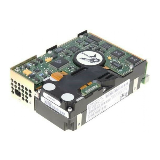
Seite 14: General Description
ST15150N/ND/W/WD Installation Guide, Rev. B General description Barracuda 4 SCSI disc drives are high-speed, random- access digital-data storage devices. ST15150N/ND drives are illustrated in Figure 1, and ST15150W/WD drives are illustrated in Figure 2. Specifications and DC power requirements for the drives are listed in tables following the figures. - Seite 15 ST15150N/ND/W/WD Installation Guide, Rev. B SCSI I/O Connector J4 J01 DC Power Connector Figure 1. Barracuda disc drive (N/ND) SCSI I/O Connector Pin 1 DC Power Connector Figure 2. Barracuda disc drive (W/WD)
- Seite 16 ST15150N/ND/W/WD Installation Guide, Rev. B Specifications Characteristics ST15150N/ND ST15150W/WD Interface SCSI-2 Fast Fast & Wide Multi-segmented cache Physical 1,024 Kbytes 1,024 Kbytes Available to users 960 Kbytes 960 Kbytes Capacity Unformatted 5,062 Mbytes 5,062 Mbytes Formatted 4,294 Mbytes 4,294 Mbytes Recording Cylinders (user accessible) 3,711 3,711...
- Seite 17 ST15150N/ND/W/WD Installation Guide, Rev. B DC power requirements for ST15150N/ND drives Single-ended Differential + + + + + 5V + + + + + 12V + + + + + 5V + + + + + 12V Voltage ± ± ± ± ± 5% ± ± ± ± ± 5% ±...
- Seite 18 See the +12V current profile in the Barracuda 4 Product Manual (publication number 83328880). This condition occurs when the Motor Start option is enabled and the drive has not yet received a Start Motor command.
-
Seite 19: Initial Setup Information
ST15150N/ND/W/WD Installation Guide, Rev. B continued from previous page Operating condition is a third-stroke seek at OD and Read One Track. The command is issued every 0.075 seconds. No terminator power. See Section 11.7.3.4 in the Barra- cuda 4 Product Manual. With all power-saving features enabled. - Seite 20 ST15150N/ND/W/WD Installation Guide, Rev. B Each option-jumper illustration identifies the original equipment manufacturer (OEM) default factory setting. These settings are the most common ones used but are not necessarily the ones set for your particular system. Write down the original jumper settings before you make any changes.
- Seite 21 ST15150N/ND/W/WD Installation Guide, Rev. B Most Barracuda disc drives are factory set with the SCSI ID set at 0. To change the SCSI ID, install jumpers on the appropriate pins as shown in the illustration provided for your model (N/ND or W/WD). If, after completing the installation process, the drive’s LED does not show on/off activity when the host is trying to communicate with the drive, a duplicate SCSI ID may...
- Seite 22 ST15150N/ND/W/WD Installation Guide, Rev. B SCSI Connector DC Power Connector Pin 1 Select SCSI ID by placing jumpers as shown below. SCSI ID = 0 (default) SCSI ID = 1 SCSI ID = 2 SCSI ID = 3 SCSI ID = 4 SCSI ID = 5 SCSI ID = 6 SCSI ID = 7...
- Seite 23 ST15150N/ND/W/WD Installation Guide, Rev. B SCSI I/O DC Power Connector Pin 1 Pin 1 Connector 3P 2P SCSI ID = 0 (default) SCSI ID = 1 SCSI ID = 2 SCSI ID = 3 SCSI ID = 4 SCSI ID = 5 SCSI ID = 6 SCSI ID = 7 SCSI ID = 8...
- Seite 24 ST15150N/ND/W/WD Installation Guide, Rev. B Terminating the drive If you are installing a Barracuda 4 drive in a system that has other SCSI devices installed, terminate only the end devices on the SCSI chain. A SCSI “device” is any disc drive, scanner, tape backup unit, or other piece of hardware connected to your system using the SCSI bus.
- Seite 25 ST15150N/ND/W/WD Installation Guide, Rev. B of the SCSI bus, remove the Enable Drive Terminator jumper (see Figure 6). Removing the jumper disables the permanently mounted IC terminators and there- fore removes internal termination from the drive. For ST15150N drives, the Enable Drive Terminator jumper is located on J01 pins 1 and 2.
- Seite 26 ST15150N/ND/W/WD Installation Guide, Rev. B Terminator power Single-ended Barracuda 4 drives may be configured in four different ways (see Figure 7 for ST15150N drives or Figure 9 for ST15150W drives). Configure ST15150ND drives as illustrated in Figure 8. Configure ST15150WD drives by connecting a jumper on J01 pins 1 and 3 as shown in Figure 9.
- Seite 27 ST15150N/ND/W/WD Installation Guide, Rev. B Power Connector Pin 1 Pin 3 Pin 1 Pin 2 Term. power to SCSI bus. (All other J01 jumper positions are invalid for ST15150ND drives.) Figure 8. Setting ST15150ND terminator power jumpers Power Connector Pin 1 Pin 3 Pin 1 Pin 2...
- Seite 28 ST15150N/ND/W/WD Installation Guide, Rev. B Changing other applicable jumper options Barracuda 4 drives are designed for use in a wide variety of systems. Some systems may require you to change one or more of the other jumpers to meet specific system requirements;...
- Seite 29 ST15150N/ND/W/WD Installation Guide, Rev. B SCSI Connector DC Power Connector Pin 1 Parity Check option (PAR) Enable parity check of SCSI bus data (default). Disable parity check. Motor Start option (MTR) Enable motor start (default). The drive waits for the Start unit command from the host before starting the spindle motor.
- Seite 30 ST15150N/ND/W/WD Installation Guide, Rev. B Pin 1 Power Connector Write Protect option (WP) Write Protect = On (disables writing). Write Protect = Off (enables writing – default). Reserved (RES) Reserved for future use. Pin 1 Remote LED Connector* Pin 9 (top pin) is negative (cathode), Pin 10 (bottom pin) is positive (anode).
- Seite 31 ST15150N/ND/W/WD Installation Guide, Rev. B Pin 1 Parity Check option (PAR) Enable parity check of SCSI bus data (default). Disable parity check. Motor Start option (MTR) Enable motor start (default). The drive waits for the Start unit command from the host before starting the spindle motor.
- Seite 32 ST15150N/ND/W/WD Installation Guide, Rev. B Synchronizing spindles in multiple drive configurations If you are installing two or more Barracuda drives, you may (optionally) want to synchronize their spindles to reduce the latency associated with switching from one drive to another. Spindle sync cables are used to connect the drives.
- Seite 33 ST15150N/ND/W/WD Installation Guide, Rev. B For W and WD drives, use pins 11 and 12 on the J5 connector to attach the spindle sync cable. Pin 11 provides the reference index signal (REFSIG+) and pin 12 provides ground (GND). See Figure 13. SCSI I/O DC Power Connector...
- Seite 34 ST15150N/ND/W/WD Installation Guide, Rev. B Figure 14 illustrates a typical synchronized spindle configuration. After connecting each drive with spindle sync cables, you must designate a master spindle sync reference source. This master source is normally a disc drive located on the same SCSI bus as the other drives you want to synchronize with.
- Seite 35 ST15150N/ND/W/WD Installation Guide, Rev. B Providing adequate cooling The enclosure design must ensure adequate cooling for the drive. The minimum ambient temperature is 5 C. The maximum ambient temperature is 50 The drive’s product manual (83328880) describes how to evaluate the air-flow design. The evaluation consists of ensuring that the case temperatures of certain critical components remain within acceptable limits during drive operation.
-
Seite 36: Kühlung Des Systems
Die Gehäusekonstruktion muß eine ausreichende Kühlung des Laufwerkes gewährleisten. Die Umgebungstemperatur darf maximal 50 C betragen. Die Produkthandbuch Barracuda 4 (Dokument 83328880) enthalten Anweisungen zur Beurteilung der Luftstromkonstruktion. Die Beurteilung muß sicherstellen, daß sich die Gehäusetemperatur bestimmter kritischer Komponenten bei Laufwerkbetrieb innerhalb zugelassener Grenzen hält. - Seite 37 ST15150N/ND/W/WD Installation Guide, Rev. B Above unit Über der Einheit Note. Air flows in the direction shown (back to front) or in reverse direction (front to back) Under unit Hinweis. Luftstrom in der angezeigten Richtung Unter der Einheit (von vorne nach hinten) oder in umgekehrter Richtung (von hinten nach vorne) Above unit Über der Einheit...
- Seite 38 ST15150N/ND/W/WD Installation Guide, Rev. B Mounting the drive and connecting cables Do not touch the connector pins or any components on the control board without observing static-discharge precautions. Always handle the drive by the frame only. The drive may be mounted in any orientation (horizon- tally, vertically, and any combination thereof);...
-
Seite 39: Installation Des Laufwerkes Und Anschluß Der Kabel
ST15150N/ND/W/WD Installation Guide, Rev. B Installation des Laufwerkes und Anschluß der Kabel Beachten Sie beim Handhaben und Anfassen der A n s c h l u ß s t i f t e u n d K o m p o n e n t e n d i e Vorsichtsmaßnahmen zur Verhinderung statischer Aufladung. - Seite 40 ST15150N/ND/W/WD Installation Guide, Rev. B Notes: Mounting holes two on each side, 6-32 UNC. Max screw length into side of drive is 0.15 in. (3.81 mm). Mounting holes four on bottom, 6-32 UNC. Max screw length into bottom of drive is 0.15 in. (3.81 mm). Power and interface connections.
- Seite 41 ST15150N/ND/W/WD Installation Guide, Rev. B Notes: Mounting holes two on each side, 6-32 UNC. Max screw length into side of drive is 0.15 in. (3.81 mm). Mounting holes four on bottom, 6-32 UNC. Max screw length into bottom of drive is 0.15 in. (3.81 mm). Power and interface connections.
- Seite 42 ST15150N/ND/W/WD Installation Guide, Rev. B 2. Verify that all connections between the drive and the host system are correctly installed. 2. Prüfen Sie, ob alle Verbindungen zwischen dem Laufwerk und dem Host-System korrekt hergestellt sind. 3. Verify that you have correctly installed SCSI ID jump- ers (see Figures 3 and 4).
- Seite 43 ST15150N/ND/W/WD Installation Guide, Rev. B den Luftstrom zur Kühlung des Systems nicht behindern. Das Laufwerk wird über einen 4-poligen, neben dem SCSI-Anschluß befestigten Steckverbinder mit Gleichstrom versorgt. Der Ausgang eines Netzteils muß SELV (safety extra low voltage) nach IEC 950 entsprechen.
- Seite 44 ST15150N/ND/W/WD Installation Guide, Rev. B mounts. Maximizing the conductive contact area between HDA ground and system ground may reduce radiated emissions. If you do not want the system chassis to be connected to the HDA/PCB ground, you must provide a nonconductive (elec- trically isolating) method of mounting the drive in the host system.
- Seite 45 ST15150N/ND/W/WD Installation Guide, Rev. B 5. Replace the host system’s cover. 5. Setzen Sie das Gehäuseoberteil des Host-Systems wieder auf. Formatting the drive Warning. Formatting a drive erases all user data. Be sure that you understand this principle before formatting any hard disc drive. It is not necessary to format a drive which has previously been used to store data, unless your intention is to erase all user data.
- Seite 48 Seagate Technology, Inc. 920 Disc Drive, Scotts Valley, CA 95066-4544, USA Publication Number: 83328870, Rev. B, Printed in USA...