3Com Baseline Switch 2250 Plus Installationsanleitung

Verwandte Anleitungen für 3Com Baseline Switch 2250 Plus


Inhaltszusammenfassung für 3Com Baseline Switch 2250 Plus
- Seite 1 Baseline Switch 2250 Plus User Guide Installationsanleitung 3C16476CS http://www.3com.com/ Part No. 10015237 Rev. AA Published August 2006...
- Seite 2 LICENSE.TXT or Reducing the waste generated by all operations. Ensuring that all waste !LICENSE.TXT. If you are unable to locate a copy, please contact 3Com and conforms to recognized environmental standards. Maximizing the a copy will be provided to you.
-
Seite 3: Inhaltsverzeichnis
Inserting an SFP Transceiver Removing an SFP Transceiver NTRODUCING THE ASELINE WITCH Performing Spot Checks Overview of the Baseline Switch 2250 Plus Features and Capabilities ONNECTING TO THE NTERFACE Autosensing of MDI/MDIX Connections Autonegotiating 10/100 Mbps Ports Requirements for Accessing the Web Interface... - Seite 4 Backup Configuration Forgotten Static IP Address Restore Configuration Solving LED Issues Firmware Upgrade If the Problem Persists Initialize Reboot BTAINING UPPORT FOR RODUCT System Access Register Your Product System Time Purchase Value-Added Services SNMP Troubleshoot Online Configuring VLANs Access Software Downloads VLAN Telephone Technical Support and Repair Forwarding Tagged/Untagged Frames...
-
Seite 5: About This Guide
Adobe Acrobat Reader Portable Document Format Return or Enter. Do not press Return or Enter (PDF) on the 3Com World Wide Web site: when an instruction simply says “type.” Words in italics Italics are used to: http://www.3com.com... -
Seite 6: Related Documentation
Related Documentation and questions about 3Com product documentation at this e-mail address. Questions related to technical In addition to this guide, each 3Com Baseline Switch support or sales should be directed in the first 2250 Plus documentation set includes the following: instance to your network supplier. -
Seite 7: Introducing The Baseline Switch
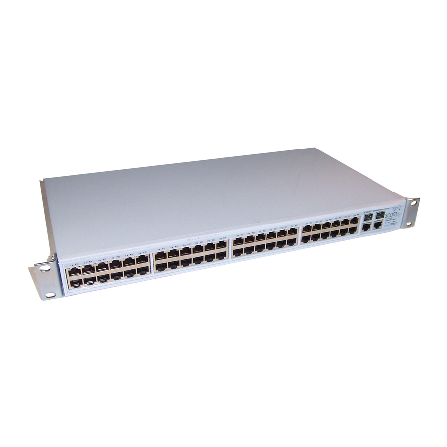
(MDI) and medium dependent Overview of the Baseline Switch 2250 Plus interface crossover (MDIX) connections. This allows The 3Com® Baseline Switch 2250 Plus is a versatile, you to connect network devices to each port using easy-to-use unmanaged switch. It is ideal for users... -
Seite 8: Sfp Ports
It differentiates traffic into topology across multiples switches, you can configure classes and prioritizes those classes automatically. 3Com Baseline Switch 2250 Plus to forward or to Traffic prioritization uses the multiple traffic queues block and discard bridge protocol data unit (BPDU) that are present in the hardware of the Switch to packets to another switch. -
Seite 9: Physical Features
Physical Features available communication paths between switches and to a traditional PBX or public telephone network. to determine the best available path and block less Only connect RJ-45 data connectors, network optimal paths. telephony systems, or network telephones to these sockets. - Seite 10 SFP transceiver is plugged in. In such a configuration, you may notice some (3) Link/Activity LEDs degradation of network performance. 3Com The following tables describe the LEDs visible on the recommends that you use devices that are capable of front of the Switch, and how to read their status autonegotiation (and that you ensure that according to color.
- Seite 11 Contact your 3Com network faulty. Contact your 3Com network supplier for further advice. supplier for further advice.
-
Seite 12: Rear Panel
Package Contents If the unit still does not operate, contact your ■ 3Com network supplier The 3Com Baseline Switch 2250 Plus package includes the following items: (6) Self-Adhesive Pads One 3Com Baseline Switch 2250 Plus unit ■ The unit is supplied with four self-adhesive rubber One power cord ■... -
Seite 13: Installing The Switch
(l'Appendice B) de ce guide. ■ unit. WARNHINWEIS: Sicherheitsinformationen. Bevor Air flow around the unit and through the vents in ■ Sie Komponenten aus dem Switch entfernen oder the side of the case is not restricted (3Com dem Switch hinzufuegen oder Instandhaltungsarbe-... -
Seite 14: Aufstellen Des Switch
HAPTER NSTALLING THE WITCH recommends that you provide a minimum of 25 3Com empfiehlt das Sie 25mm (1 Inch) mm or 1 in. clearance). Zwischenraum sicherstellen. The air is as free of dust as possible. Die Luft so frei wie möglich von Staub ist. -
Seite 15: Montagesatz Anweisungen
Rack-Mounting or Free-Standing To rack-mount the Switch: Montagesatz Anweisungen Der Switch wird mit zwei Halterungen und vier Place the unit the right way up on a hard, flat surface Schrauben geliefert. Diese werde für den Einbau in with the front facing towards you. einen Baugruppenträger benutzt. -
Seite 16: Placing Units On Top Of Each Other
3Com recommends that you install power con- When POST is complete, the Power LED turns green. ditioning, especially in areas prone to black outs, If the Power LED turns yellow after POST, it means power dips and electrical storms. -
Seite 17: Connecting A Network Device
10 or 100 Mbps link If these do not resolve the issue: Server on switched 1000 Mbps Check the 3Com Knowledgebase for a solution. To ■ connection visit the 3Com Knowledgebase Web site, start your Web browser, and then enter To connect a device to the Switch: http://knowledgebase.3com.com... -
Seite 18: Using Sfp Transceivers
3CSFP92 SFP (LX) ■ To access the latest list of approved SFP transceivers for the Switch on the 3Com Corporation World Wide Web site, enter this URL into your Internet browser: http://www.3com.com 3Com recommends using 3Com SFPs on the Switch. -
Seite 19: Removing An Sfp Transceiver
Remove the plastic protective cover, if fitted. attended to when there will be least effect on users. Connect the fiber cable. 3Com recommends periodically checking the items The transceiver connects to the network using a listed in Table duplex LC connector. - Seite 20 2: I HAPTER NSTALLING THE WITCH...
-
Seite 21: Connecting To The Web
The Discovery application, which is included on ■ If you only want the Switch to function as a basic 3Com Baseline Switch 2250 Plus CD-ROM that is layer 2 switch, you do not need to access the Web supplied with your Switch interface and configure the Switch. - Seite 22 Switch, and then click Next. Click Finish. If the computer has only one adapter, click Next. Discovery searches the network for 3Com devices. The logon dialog box for the Web interface appears. When detection is complete, the Discovered Devices screen displays detected network devices.
-
Seite 23: Logging On To The Web Interface
Logging On to the Web Interface Logging On to the Web Interface Navigating the Web Interface After the Web interface loads in your Web browser, The Web interface has been designed to enable you the first page that appears is the logon screen. On to easily perform advanced configuration tasks and this screen, you need to enter the administration user view information about the Switch. - Seite 24 3: C HAPTER ONNECTING TO THE NTERFACE Table 10 lists the available items on the menu. Menu Item Description SNMP Contains tabs that allow you to: Table 10 Available Menu Items Display SNMP summary information. Menu Item Description ■ Enable or disable SNMP. ■...
-
Seite 25: Buttons
Navigating the Web Interface Menu Item Description Menu Item Description Link Aggregation Contains tabs that allow you to: 802.1X Settings Contains tabs that allow you to: Display link aggregation summary. Display 802.1X information. ■ ■ Create an aggregation group. Display 802.1X detailed information per ■... -
Seite 26: Accessing The Interface Without Using Discovery
3: C HAPTER ONNECTING TO THE NTERFACE Manually Assigned (Static) IP Address Accessing the Interface Without Using If you assigned a static IP address to the Switch, you Discovery need to use that IP address to access the Web The Discovery application works by automatically interface the next time you want to configure the detecting the IP address that is assigned to the Switch. -
Seite 27: Onfiguring The
ONFIGURING THE WITCH This chapter provides information on how to Device Summary Information configure the Switch’s advanced features. Topics include: The Device Summary screen, which automatically loads after you log on to the Web interface, provides Device Summary Information ■ a snapshot of the Switch’s basic settings and versions Administration Settings ■... - Seite 28 Enter a 0 to disable polling. Color Key Description of the color coding. Figure 11 Color Key If you request for technical assistance from 3Com Support, you may be asked to print out the information on this screen. Polling Interval Enter the interval in seconds you would like the Switch to refresh.
-
Seite 29: Administration Settings
The Switch repeats step 2 until an unused IP address connect to the Web interface. is found. 3Com recommends using automatic IP configuration Automatic IP Configuration only for the initial setup. Once you gain access to the When you power on the Switch for the first time, it... -
Seite 30: Ip Setup
4: C HAPTER ONFIGURING THE WITCH IP Setup Backup Configuration To set the IP address for the Switch: To save the Switch configuration settings: Click Administration, then IP Setting on the menu. Click Administration, then Backup Configuration on The IP Settings screen appears. Follow the IP Setup the menu. -
Seite 31: Firmware Upgrade
Switch will restart. Although the upgrade process has been designed to preserve your Firmware Upgrade configuration settings, 3Com recommends that you The Upgrade facility allows you to install on the make a backup of the configuration beforehand, in... -
Seite 32: Reboot
To ensure that unauthorized users do not access the the Switch. Web interface, 3Com recommends that you set an admin password when you first configure the Switch. Reboot Even if you do not intend to actively manage the... - Seite 33 Administration Settings Create User Figure 18 Modify User Screen This page allows you to create a user and define the access level and password for that user. Figure 17 CreateUser Screen Remove User To remove a user from the Switch, click on the user name, then click Remove.
-
Seite 34: System Time
4: C HAPTER ONFIGURING THE WITCH System Time Summary Displays the list community access strings. Click Administration, then System Time on the menu. This screen allows you to set the system time. You can Figure 21 SNMP Summary Screen set the Year, Month, Day, Hours, Minutes, and Seconds. -
Seite 35: Configuring Vlans
Configuring VLANs Figure 23 SNMP Add Screen Configuring VLANs A virtual LAN (VLAN) is a collection of network nodes that share the same collision domain, regardless of their physical location or connection point in the network. A VLAN serves as a logical workgroup with no physical barriers, and allows users to share information and resources as though located on the same LAN. -
Seite 36: Vlan
4: C HAPTER ONFIGURING THE WITCH VLAN Available option on the Setup screen include: VLAN ID – ID of configured VLAN (1-4094, no ■ Click Device, then VLAN on the menu. A screen leading zeroes) appears with seven tabs that include: Setup For examples on setting up VLANs, refer to “Sample... - Seite 37 Configuring VLANs Modify Port Figure 26 Modify VLAN Screen Use the Modify Port screen to modify the VLAN membership of a port. Figure 27 Modify Port Screen Select a membership use. Available options for each port include (only one option can be associated with a Enter a set of VLANs or select all VLANs to configure, single port): then click Select.
- Seite 38 4: C HAPTER ONFIGURING THE WITCH Rename Remove Use the Rename screen to change the name of a Use the Remove screen to remove a VLAN. VLAN. Figure 29 Remove Screen Figure 28 Rename Screen Enter a set of VLANs or select all VLANs to add to the remove list, then click Select.
-
Seite 39: Forwarding Tagged/Untagged Frames
Configuring VLANs Port Detail Figure 31 VLAN Detail Screen Choose a port to display the tagged and untagged VLAN memberships it is associated with. Figure 30 Port Detail Screen VLAN Detail Forwarding Tagged/Untagged Frames Use this screen to display detailed VLAN information. Each port on the Switch is capable of passing tagged or untagged frames. -
Seite 40: Sample Vlan Configurations
VLAN 2 port on each Switch is set to Tagged, and that these Port 1 ports are connected. Port 3 Baseline Switch 2250 Baseline Switch 2250 Plus Port 26 Server Server in VLAN 2 in VLAN 1 If you want to add ports 1, 3, and 26 to VLAN2 (as... -
Seite 41: Spanning Tree
Configuring VLANs Connect the Tagged port on Switch 1 (in this Figure 33 Tagged VLAN Configuration example, port 16) to the Tagged port on Switch 2 (in this example, port 8). Those ports on Switch 1 that are members of VLAN2 can now communicate with those ports on Switch 2 that are members of VLAN2. -
Seite 42: Igmp Snooping
4: C HAPTER ONFIGURING THE WITCH After all the bridges on the network have determined to receive the multicast service. This procedure is the configuration of their ports, each bridge only called multicast filtering. forwards traffic between the Root Port and the ports The purpose of IP multicast filtering is to optimize a that are the Designated Bridge Ports for each network switched network’s performance, so multicast packets... -
Seite 43: Broadcast Storm
Configuring Port Settings Broadcast Storm current connection status of each port or shut down or disable ports. Use the Broadcast Storm page to set the Switch’s broadcast storm control and threshold limits. The Port menu includes five items: A broadcast storm is an incorrect packet sent out on a Administration ■... - Seite 44 4: C HAPTER ONFIGURING THE WITCH Figure 38 Port Administration Summary Screen Figure 39 Port Administration Detail Screen Setup Use the Setup tab to configure the port settings. The following options are available: Port State – Enables and disables the port. ■...
-
Seite 45: Speed/Duplex For 1000 Mbps Connections
Configuring Port Settings Duplex – Sets the duplex mode of the port. CAUTION: Before manually setting a port to ■ Available options include auto, half, and full. full-duplex, verify that the device connected to the port is also manually set to the same speed and If you modify any of these settings, click Apply to save duplex setting. - Seite 46 4: C HAPTER ONFIGURING THE WITCH Guidelines for Creating Trunks Figure 41 Link Aggregation Summary Screen Any port on the Switch can be used for creating a ■ trunk. This switch supports a maximum of four trunks. ■ Each trunk may contain up to four members. ■...
-
Seite 47: Spanning Tree Per Port
Configuring Port Settings Modify Figure 44 Link Aggregation Remove Screen Use the Modify tab reassign port members to a link aggregation group. Figure 43 Link Aggregation Modify Screen To remove a link aggregation group: From the link aggregation group list, select the aggregated group to remove. - Seite 48 4: C HAPTER ONFIGURING THE WITCH the Root Bridge generates BPDUs (Bridge Protocol Figure 45 Spanning Tree Summary Screen Data Units) on all ports at a regular interval known as the Hello Time. All other spanning tree-compliant devices on the network have a designated Root Port. This is the Port nearest the Root Bridge and it is used for receiving the BPDUs initiated by the Root Bridge.
-
Seite 49: Port Mirroring
Configuring Port Settings device with the lowest MAC address will then Figure 46 Spanning Tree Detail Screen become the root device. If you modify any of these settings, click Apply to save your changes. Figure 47 Spanning Tree Setup Screen Setup Use the Setup tab to configure the spanning tree settings for each port. -
Seite 50: Qos Voip Traffic Settings
4: C HAPTER ONFIGURING THE WITCH Figure 48 Port Mirroring Screen QoS VoIP Traffic Settings Using the Web interface, you can configure the Voice over Internet Protocol (VoIP) settings. The QoS VoIP Traffic Setting menu includes six tabs: Summary ■ Setup ■... - Seite 51 QoS VoIP Traffic Settings Setup To configure the Voice VLAN settings for the ports: Use the Setup tab to configure the global settings for Select Voice VLAN Mode and Security settings. Voice VLAN. The following options are available: Select the ports you would like to apply these settings Voice VLAN Status –...
- Seite 52 4: C HAPTER ONFIGURING THE WITCH OUI Modify Figure 52 QoS Port Detail Screen Use the OUI Modify tab to add to the list of Organizational Unique Identifier. The following options are available: Telephony OUI – Input a new company identifier to ■...
-
Seite 53: Security
Security Figure 55 RADIUS Client Detail Screen Security Using the Web interface, you can configure the RADIUS Client and 802.1X settings. The Security menu includes two items: RADIUS Client ■ 802.1X Settings ■ RADIUS Client Remote Authentication Dial-in User Service (RADIUS) is a logon authentication protocol that uses software running on a central server to control access to RADIUS-aware devices on the network. -
Seite 54: 802.1X Settings
4: C HAPTER ONFIGURING THE WITCH Figure 56 RADIUS Client Configure Screen Figure 57 802.1X Summary Screen 802.1X Settings Detail The IEEE 802.1X (dot1x) standard defines a Use the Detail tab to display detailed 802.1X port-based access control procedure that prevents authentication information for a port. - Seite 55 Security Setup Max Count – The maximum number of hosts that ■ can connect to a port when the Multi-Host Use the Setup tab to configure the 802.1X operation mode is selected. (Range: 1-1024; authenticaion settings. The following fields are Default: 5) available: Reauthentication Period –...
-
Seite 56: Monitoring
4: C HAPTER ONFIGURING THE WITCH Cable Diagnostics Monitoring The Switch provides cable diagnostic, which helps you Using the Web interface, you can display address detect and resolve issues with the attached cables. table information and cable diagnostics. The Cable Diagnostics menu includes two tabs: The Monitoring menu includes two items: Summary ■... - Seite 57 Monitoring Diagnostics Use the Diagnostics tab to display individual port information on Test Result, Cable Fault Distance, and Last Update. Figure 62 Cable Diagnostic Screen...
- Seite 58 4: C HAPTER ONFIGURING THE WITCH...
-
Seite 59: Troubleshooting
RESET button on the Initialize tab of the Administration menu. After you click RESET, If you encounter an issue that is not listed here and a confirmation message appears. Click OK to con- you cannot solve it, check the 3Com Knowledgebase firm. before contacting http://knowledgebase.3com.com your local technical support representative. -
Seite 60: Forgotten Static Ip Address
The SFP module is correctly inserted. ■ This section lists some issues that are related to the A 3Com SFP module is being used. Refer to ■ LEDs on the front panel of the Switch. For “Approved SFP Transceivers” on page 18 information on basic LED checks, refer to the details. -
Seite 61: If The Problem Persists
If the problem persists and the unit still does not The ports are configured for half-duplex operation ■ operate successfully, contact your 3Com network supplier with the following information before All ports appear to show continual activity. returning the unit: There may be broadcast storms on the network. - Seite 62 5: T HAPTER ROUBLESHOOTING...
-
Seite 63: A Obtaining Support For
Register your product at http://eSupport.3com.com/. 3Com eSupport Troubleshoot Online services are based on accounts that you create or You will find support tools posted on the 3Com web have authorization to access. First time users must site at http://www.3com.com/... -
Seite 64: Telephone Technical Support And Repair
A: O PPENDIX BTAINING UPPORT FOR RODUCT , or under the To send a product directly to 3Com for repair, you http://eSupport.3com.com/ Product Support heading at must first obtain a return authorization number http://www.3com.com/ (RMA). Products sent to 3Com, without authorization... - Seite 65 Taiwan 00801 611 261 You can also obtain support in this region using the following Thailand 001 800 611 2000 URL: http://emea.3com.com/support/email.html You can also obtain support in this region using the following e-mail: apr_technical_support@3com.com Country Telephone Number Or request a repair authorization number (RMA) by fax using...
- Seite 66 Country Telephone Number Antigua 1 800 988 2112 You can also obtain support in this region using the follow- Argentina 0 810 444 3COM ing: Aruba 1 800 998 2112 Spanish speakers, enter the URL: Bahamas 1 800 998 2112 http://lat.3com.com/lat/support/form.html...
-
Seite 67: B Safety Information
AFETY NFORMATION Important Safety Information You can find the 3Com Switch Family Safety and Please refer to the safety information found in the Regulatory Information manual on the product 3Com Switch Family Safety and Regulatory Informa- CD-ROM that was included with your switch. You can tion manual included with this product. - Seite 68 B: S PPENDIX AFETY NFORMATION...
-
Seite 69: C Technical Information
ECHNICAL NFORMATION Physical Related Standards Width 440 mm (17.3 in.) The 3Com Baseline Switch 2250 Plus has been Depth 215 mm (8.5 in.) designed to the following standards: Height 41 mm (1.6 in.) or 1U Functional ISO 8802-3, IEEE 802.3 (Ethernet), Weight 3.1 kgs (6.83 lbs) - Seite 70 C: T PPENDIX ECHNICAL NFORMATION...
-
Seite 71: Glossary
LOSSARY 10BASE-T the IEEE 802.3 standard for Ethernet and is an operation that takes place in a few milliseconds. The IEEE specification for 10 Mbps Ethernet over Autonegotiation must be enabled for the Category 3, 4 or 5 twisted pair cable. 1000BASE-T ports to operate at 1000 Mbps, full-duplex. - Seite 72 LOSSARY category 5e cables Ethernet address One of five grades of Twisted Pair (TP) cabling defined See MAC address. by the EIA/TIA-568 standard. Category 5e can be Fast Ethernet used in Ethernet (10BASE-T), Fast Ethernet (100BASE-TX) and Gigabit Ethernet (1000BASE-T) An Ethernet system that is designed to operate at 100 networks, and can transmit data at speeds of up to Mbps.
- Seite 73 LOSSARY standard way for VLANs to communicate across IP Address switched networks. Internet Protocol Address. A unique identifier for a device attached to a network using TCP/IP. The IEEE 802.1p address is written as four octets separated with An IEEE standard for providing quality of service (QoS) periods (full-stops), and is made up of a network in Ethernet networks.
- Seite 74 LOSSARY Most devices that connect to a LAN have a MAC address assigned to them as they are used to identify Small Form Factor Pluggable (SFP) Connectors are other devices on a network. MAC addresses are 6 based on an open standard that enables hot bytes long.
- Seite 75 LOSSARY developed for the interconnection of networks. Originally a UNIX standard, TCP/IP is now supported on almost all platforms, and is the protocol of the Internet. TCP relates to the content of the data travelling through a network — ensuring that the information sent arrives in one piece when it reaches its destination.
- Seite 76 LOSSARY...
-
Seite 77: Index
NDEX Numbers 1000BASE-LX 71 Ethernet 72 LAN defined 73 1000BASE-SX 71 LED issues 60 1000BASE-T 71 LEDs 100BASE-TX 71 Link/Activity 10 10BASE-T 71 Module Active 11 Fast Ethernet 72 Power 12 forgotten IP address 59 link aggregation 45 forgotten password 59 local area network 73 free-standing 14 auto IP configuration 29... - Seite 78 NDEX changing 32, 34 troubleshooting 59 default (blank) 32 forgotten IP address 59 setting 28 forgotten password 59 physical features 9 LED-related issues 60 port settings POST failed 17 configuring 43, 50, 53 trunking See link aggregation ports RJ-45 11 SFP 8, 10 positioning 13 user name...
-
Seite 79: Regulatory Notices
EGULATORY OTICES FCC S VCCI S TATEMENT TATEMENT This equipment has been tested and found to comply with the limits for a Class A digital device, pursuant to part 15 of the FCC rules. These limits are designed to provide reasonable protection against harmful interference when the equipment is operated in a commercial environment.