Inhaltsverzeichnis
Werbung
Verfügbare Sprachen
Verfügbare Sprachen
Quicklinks
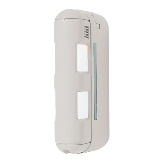
S145-22X
notice d'installation - p. 2
a
Détecteur de mouvement IP55 sepio radio,
façades, spécial animaux, 2 x 12 m
manuale di installazione - p. 15
y
Rivelatore speciale animali esterno 2 direzioni x 12 m
Montageanleitung - S. 28
e
IR-Bewegungsmelder außen 2 x 12 m
manual de instalacion - p. 41
r
Detector Movimiento IP55,radio, fachada inmune
mascotas
installatiegids - p. 54
i
Bewegingsdetector IP55 LS radio, gevel special
voor huisderen
Installation manual - p. 67
z
Outdoor motion detector 2 x 12 m
804863/F
Werbung
Kapitel
Inhaltsverzeichnis

Verwandte Anleitungen für hager S145-22X

Inhaltszusammenfassung für hager S145-22X
- Seite 1 S145-22X notice d’installation - p. 2 Détecteur de mouvement IP55 sepio radio, façades, spécial animaux, 2 x 12 m manuale di installazione - p. 15 Rivelatore speciale animali esterno 2 direzioni x 12 m Montageanleitung - S. 28 IR-Bewegungsmelder außen 2 x 12 m manual de instalacion - p.
-
Seite 2: Inhaltsverzeichnis
Sommaire Recommandations 1. Présentation Tout accès aux composants internes peut 1. Présentation ............2 Le détecteur de mouvement pour façades, endommager l’appareil par déchar ges spécial animaux 2 x 12 m est spécialement 2. Préparation............4 électro statiques. conçu pour détecter l’intrus avant même 2.1 Ouverture ............4 Lors d’une intervention sur l’appareil prendre 2.2 Alimentation...........4... - Seite 3 Réceptacle arrière Module de détection Capot Boîtier radio Voyant LED Ensemble de faisceaux de détection Micro-interrupteur supérieur de sélection de la sensibilité Micro-interrupteur des options de fonctionnement Ensemble de faisceaux de détection inférieur Vis de fermeture Autoprotection Vis de fermeture x 2 Module de détection avec boitier radio ouvert Carte radio Connecteur...
-
Seite 4: Préparation
2. Préparation 2.1 Ouverture 2.2 Alimentation Connecter la pile. 1. Retirer le capot. 2. Enlever le réceptacle arrière. 3. Ouvrir le boîtier radio. A la mise sous tension, le détecteur effectue un autotest. Si l’autotest est : • correct, le voyant s’éclaire 2 s, •... -
Seite 5: Apprentissage
3. Apprentissage 2. Réaliser l’apprentissage en composant la séquence ci-dessous : ATTENTION : lors de l’apprentissage, il est inutile de placer le produit à apprendre à ATTENTION : le n° du détecteur est attribué automatiquement par la centrale lors de proximité... -
Seite 6: Paramétrage
4. Paramétrage En configuration usine, le détecteur de Séquence de N° du paramètre Niveau d’alarme Valeur du paramètre mouvement est configuré en préalarme paramétrage Intrusion Préalarme faible (pour les réactions du système cf. Dissuasion 3 (paramétrage usine) Guide d’installation de votre centrale). Il est Avertissement possible de modifier le niveau d’alarme à... -
Seite 7: Précaution De Pose
5. Précautions de pose ATTENTION : respecter une distance d’au moins 2 mètres entre chaque produit, excepté entre deux détecteurs. • de manière à ce que les faisceaux de • en direction d’objet en mouvement Le détecteur doit être placé : •... -
Seite 8: Installation
6. Installation 6.1 Test de la liaison radio 6.2 Fixation 1. Avant de fixer les détecteurs, les disposer 1. Percer les trous de fixation en vous 2. Fixer le réceptacle à proximité du point de fixation et vérifier aidant du gabarit de perçage présent arrière sur le mur les liaisons radio avec la centrale. -
Seite 9: Configuration Et Réglages De La Détection
7. Configuration et réglages de la détection 7.1 Portée de détection Le faisceau supérieur reste toujours parallèle au sol. Etant donné que les faisceaux (inférieur et supérieur) doivent être coupés simultanément pour déclencher une alarme, la portée du détecteur est limitée à la portée du faisceau inférieur. Détection : les faisceaux inférieurs et supérieurs Pas de détection : seul le faisceau inférieur Pas de détection : seul le faisceau supérieur... - Seite 10 Le faisceau inférieur est ajusté en fonction de la position de la lentille comme le montrent les figures ci-dessous. Pour régler la portée de détection : 1. Séparer le support de lentille 2. Ajuster séparément les portées de détection en faisant glisser 3.
-
Seite 11: Ajustement Horizontal De L'angle De Détection
7.2 Ajustement horizontal de l’angle de détection En cas d’obstacle gênant les faisceaux de Pour ajuster l’angle de détection : détection, il est possible de les décaler 1. Séparer le support de lentille et le capot (cf. étape 1. Portée de détection). horizontalement de 3°. -
Seite 12: Réglage De La Sensibilité
7.3 Réglage de la sensibilité 7.4 Réglage des options de fonctionnement Ce réglage permet d'ajuster le niveau de Le réglage des options se fait par 3 micro-interrupteurs situés à l’intérieur du détecteur. sensibilité du détecteur. Pour des conditions d’environnement : Détecteur en mode test Les voyants LED s’allument lors de chaque •... -
Seite 13: Test De Fonctionnement
8.1 Test de la zone de détection 8.2 Essai réel 9.1 Signalisation des anomalies 9.2 Changement de l’alimentation 1. Mettre le micro-interrupteur 1 1. Passer la centrale en mode La centrale prend en compte ATTENTION : les paramétrages sur ON. utilisation en composant : l’anomalie tension, l’anomalie du détecteur sont sauvegardés... -
Seite 14: Entretien
Détecteur de mouvement IP55 sepio radio, code installateur façades, spécial animaux, 2 x 12 m 5. Refaire un test de fonctionnement S145-22X (cf. § Test de fonctionnement). Principe de détection infrarouge passif Il est impératif de remplacer la pile lithium Couverture 2 ensembles de faisceaux réglables de 2 à... -
Seite 15: Presentazione
Sommario Raccomandazioni 1. Presentazione Una scarica elettrostatica proveniente dalle 1. Presentazione ..........15 Il rivelatore di movimento esterno 2 x 12 m dita o da altri conduttori elettrostaticamente è ideato in particolare per rilevare la presenza 2. Preparazione ..........17 carichi può... - Seite 16 Involucro posteriore Modulo di relevazione Copertura Scatola radio Spia Luminosa LED Gruppo fasci di rilevazione superiore Microinterruttore di selezione sensibilità Microinterruttore modalità di funzionamento Gruppo fasci di rilevazione inferiore Vite di Autoprotezione chiusura Vite di chiusura x 2 Modulo di relevazione con Scatola radio aperta Scheda radio Connettore...
-
Seite 17: Preparazione
2. Preparazione 2.1 Apertura 2.2 Alimentazione Collegate la pila. 1. Levate la 2. Togliete l’involucro posteriore. 3. Aprite la scatola radio. Al momento dell’alimentazione, il rivelatore copertura. effettua un autotest: • se l’autotest è corretto, la spia rossa si accende fissa per 2 sec., •... -
Seite 18: Apprendimento
3. Apprendimento 2. Effettuate la procedura descritta di seguito: ATTENZIONE: al momento del collegamento, è inutile posizionate il prodotto da collegare ATTENZIONE: il numero del rivelatore viene attribuito automaticamente dalla centrale durante vicino alla centrale, al contrario, l’apprendimento. è raccomandabile allontanarlo un po’ (posizionare il prodotto ad almeno 2 metri dalla centrale). -
Seite 19: Programmazione
4. Programmazione Di fabbrica, il rilevatore di movimento Procedura di N° parametro Livello d’allarme Valore del parametro è configurato per un livello di preallarme programmazione Intrusione Preallarme debole (per le reazioni del sistema, vedi Dissuasione 3 (programmazione di fabbrica) la Guida d’installazione della centrale). Avviso E’... -
Seite 20: Precauzioni Per L'installazione
5. Precauzioni per l’installazione ATTENZIONE: E’ necessario mantenere una distanza di almeno due metri tra ogni apparecchiatura del sistema, tranne che tra due rivelatori. • in modo che i fasci di rilevazione siano • in direzione di oggetti in movimento (rami, Il rivelatore deve essere installato: •... -
Seite 21: Installazione
6. Installazione 6.1 Test del collegamento radio 6.2 Fissaggio 1. Prima di fissare le apparecchiature, 1. Effettuate i fori di fissaggio servendovi 2. Fissate l’involucro posizionatele in prossimità dei punti di del modello di foratura presente sulla posteriore del installazione definitiva, e verificate i scatola di imballaggio. -
Seite 22: Configurazione E Regolazioni Della Rilevazione
7. Configurazione e regolazioni della rilevazione 7.1 Portata di rilevazione Il fascio superiore è sempre parallelo al terreno. Dato che i fasci (inferiore e superiore) devono essere interrotti contemporaneamente per attivare l’allarme, la portata del rilevatore è limitata a quella del fascio inferiore. Rilevazione: i fasci inferiore e superiore sono Nessuna rilevazione: solo il fascio inferiore Nessuna rilevazione: solo il fascio superiore... - Seite 23 Il fascio inferiore viene regolato in base alla posizione della lente, come indicato nelle seguenti figure. Per regolare la portata di rilevazione: 1. Separate il supporto della 2. Regolate separatamente le portate di rilevazione facendo scorrere 3. Se desiderate regolare lente dalla copertura come verticalmente le lenti sulle posizioni A, B, C o D.
-
Seite 24: Regolazione Orizzontale Dell'angolo Di Rilevazione
7.2 Regolazione orizzontale dell’angolo di rilevazione Nel caso ci fosse un ostacolo che disturba Per regolare l’angolo di rilevazione: i fasci di rilevazione, è possibile spostarli 1. Separate il supporto della lente e il coperchio (v. 1. Portata di rilevazione). orizzontalmente di 3°. -
Seite 25: Regolazione Della Sensibilità
7.3 Regolazione della sensibilità 7.4 Regolazione delle modalitàdi funzionamento Questa regolazione permette di calibrare il La regolazione delle modalità si effettua tramite 3 microinterruttori che si trovano all’interno livello di sensibilità del rilevatore. del rilevatore. Per condizioni ambientali: Rilevatore in modo test: •... -
Seite 26: Test Di Funzionamento
8.1 Test della zona di rilevazione 8.2 Prova reale 9.1 Segnalazione di anomalie 9.2 Cambio della pila 1. Portate il microinterruttore 1 1. Riportate la centrale in modo La centrale rileva l’anomalia ATTENZIONE: la programmazione su posizione ON. uso digitando: tensione, l’anomalia effettuata sul rivelatore viene 2. -
Seite 27: Manutenzione
La pila deve tassativamente essere sostituita 2 direzioni x 12 m esclusivamente con una dello stesso tipo (BatLi05 - 3,6 V). Gettate poi S145-22X la pila scarica in uno degli appositi contenitori previsti per questo scopo. Principio di rilevazione infrarosso passivo... -
Seite 28: Beschreibung
Inhalt Wir empfehlen 1. Beschreibung Jeder Zugriff auf das Geräteinnere kann das 1. Beschreibung..........28 Der IR-Bewegungsmelder für außen mit einer Gerät durch elektrostatische Entladungen Reichweite von 2 x 12 m wurde speziell zur 2. Vorbereitung............ 30 beschädigen. Detektion eines Eindringlings vor dem 2.1 Öffnen ............30 Daher sind hierfür folgende 2.2 Stromversorgung.........30... - Seite 29 Hintere Bodenplatte Detektionsmodul Deckel Gehäuse des Funkteils Obere Detektionszone Dipschalter zur Wahl der Empfindlichkeit Dipschalter für Betriebsartenwahl Untere Detektionszone Sabotageschutz Deckelschraube Deckelschraube x 2 Detektionsmodul mit geöffnetem Funkgehäuse Funk-Leiterplatte Batteriestecker Batterie Programmier-LED Halterung Test-Taste für Linse Deckel...
-
Seite 30: Vorbereitung
2. Vorbereitung 2.1 Öffnen 2.2 Stromversorgung Die Batterie anschließen. 1. Den Deckel 2. Die hintere Bodenplatte 3. Gehäuse des Funkteils Bei Spannungslegung führt der Melder einen abnehmen. abnehmen. öffnen. Selbsttest durch. Dieser ist: • korrekt, wenn die LED 2 Sek. lang leuchtet •... -
Seite 31: Einlernen
3. Einlernen 2. Den Einlernvorgang wie unten gezeigt durchführen: ACHTUNG: beim Einlernen muss das einzulernende Gerät nicht in der Nähe der ACHTUNG: Die Meldernummer wird automatisch beim Einlernen durch die Zentrale vergeben. Zentrale platziert werden. Wir empfehlen hingegen, dieses etwas von der Zentrale zu entfernen (mindestens 2 m Abstand halten). -
Seite 32: Programmieren
4. Programmieren Werkseitig ist der Melder auf leisen Voralarm Programmierung: Funktions-Nr. Lautstärke des Alarms Einstellung (Wert) eingestellt (Details zu den Reaktionen der Einbruch Voralarm Anlage finden Sie in der Montageanleitung Warnstufe 2 3 (Voreinstellung) der Zentrale). Diese Einstellung kann auf Warnstufe 1 Wunsch geändert werden: Programmier... -
Seite 33: Projektierung
5. Projektierung ACHTUNG: Mindestens 2 m Abstand zwischen jedem Gerät einhalten; Ausnahme: Melder. • Die Detektionsbereiche parallel zur Wand • Auf sich vom Wind bewegende Gegen - Den Melder wie folgt platzieren: • In 0,80 bis 1,20 m Höhe ausrichten stände gerichtet (Zweige, Büsche, Fahnen) •... -
Seite 34: Montage
6. Montage 6.1 Testen der Funkverbindung 6.2 Montage 1. Vor der Endmontage den Melder an den 1. Befestigungslöcher mit Hilfe der 2. Die hintere vorgesehenen Montageort halten und Bohrschablone auf der Verpackung Bodenplatte mit einen Funktest zur Zentrale durch-führen. bohren. den Dübeln und Bei korrekter Funkverbin dung nennt die geeigneten... -
Seite 35: Konfiguration Und Detektionseinstellungen
7. Konfiguration und Detektionseinstellungen 7.1 Detektionsreichweite Die oberen Detektionszonen verlaufen immer parallel zum Boden. Dadurch dass die Detektionszonen (oben und unten) gleichzeitig eine Bewegung erkennen müssen, damit ein Alarm ausgelöst wird, entspricht die Reichweite des Melders der der unteren Detektionszonen. Detektion: Die unteren und oberen Zonen Keine Detektion: Nur die unteren Detektionszonen Keine Detektion: Nur die oberen Detektionszonen... - Seite 36 Die untere Detektionszone wird abhängig von der Einstellung der Linse gemäß den folgenden Abbildungen ausgerichtet. Zum Einstellen der Detektionsreichweite: 1. Den Deckel wie 2. Die Detektionsreichweiten durch senkrechtes Verschieben der 3. Wenn Sie den nebenstehend gezeigt vom Linsen auf die Markierungen A, B, C oder D getrennt einstellen. Detektionswinkel in Linsenträger abnehmen.
-
Seite 37: Waagerechtes Ausrichten Des Detektionswinkels
7.2 Waagerechtes Ausrichten des Detektionswinkels Falls Hindernisse die Detektionsbereiche Zum Einstellen des Detektionswinkels: beeinträchtigen, können diese um 3° in 1. Den Deckel vom Linsenträger abnehmen (siehe Schritt 1. „Detektionsreichweite“). waagerechter Richtung verschoben werden. 2. Die Detektionswinkel durch ein Verschieben der Linsen in waagerechter Richtung getrennt einstellen. -
Seite 38: Empfindlichkeit Einstellen
7.3 Empfindlichkeit einstellen 7.4 Betriebsarten wählen Hierdurch kann die Empfindlichkeit des Die gewünschten Betriebsarten werden über die 3 Dipschalter im Melder eingestellt. Melders an die jeweiligen Umgebungs - bedingungen angeglichen werden: Melder im Testbetrieb • schwierige Bedingungen (Wind, starke Die LED’s leuchten bei jeder Detektion auf. Lichteinstrahlung,etc.): Empfindlichkeit Melder im Normalbetrieb reduzieren (Position L) -
Seite 39: Funktionstest
8.1 Austesten des Detektionsbereichs 8.2 Test unter realen Bedingungen 9.1 Anzeige von Störungen 9.2 Batteriewechsel 1. Den Dipschalter 1 auf ON 1. Die Zentrale in den Die Zentrale registriert eine ACHTUNG: Die Einstellungen stellen. Normalbetrieb schalten: Batterie störung, Sabotage und des Melders bleiben 2. -
Seite 40: Pflege
4. Die Zentrale wieder in den Normal-betrieb schalten: Technische Daten IR-Bewegungsmelder außen 2 x 12 m 5. Funktionstest wiederholen (siehe Funktionstest). S145-22X Detektionsart Passiv-Infrarot Verwenden Sie nur den mitgelieferten Batterietyp (BatLi05, 3,6 V). Überwachungsbereich 2 Detektionszonen jeweils einstellbar von 2 bis 12 m... -
Seite 41: Presentación
Sumario Recomendaciones 1. Presentación Todo acceso a los componentes internos 1. Presentación ........... 41 El detector de movimiento exterior 2 x 12 m puede ocasionar una descarga de fue diseñado especialmente para detectar al 2. Preparación............. 43 electricidad estática procedente de los intruso incluso antes de que fuerce el 2.1 Apertura ............43 dedos o de otro conducto electroestático,... - Seite 42 Receptáculo trasero Módulo de detección Carcasa Caja de radio Visor LED Conjunto de haces de detección Micro-interruptor superior de selección de sensibilidad Micro-interruptor de opciones de funcionamiento Conjunto de haces de detección inferior Tornillo de cierre Autoprotección Tornillo de cierre x 2 Módulo de detección con caja de radio abierta Carta radio...
-
Seite 43: Preparación
2. Preparación 2.1 Apertura 2.2 Alimentación Conectar la pila. 1. Quitar la tapa. 2. Quitar el receptáculo trasero. 3. Abrir la caja de radio. A la conexión de la alimentación, el detector efectúa un autotest: • correcto: el visor se ilumina 2 seg., •... -
Seite 44: Programación
3. Programación 2. Realizar la parametrización componiendo la secuencia: ATENCIÓN: durante la programación, es inútil colocar el producto a programar cerca de la ATENCIÓN: el nº de detector es atribuido por la central con la parametrización. central, al contrario, le aconsejamos colocar el producto a programar a cierta distancia (colocar el producto a al menos 2 metros de la “bip, detector X... -
Seite 45: Parametrizaciones
4. Parametrizaciones En configuración fábrica, el detector de Secuencia de N° de parámetro Nivel de alarma Valor del parámetro movimiento está configurado en prealarma parametrización Intrusión Pre-alarma débil (para las reaccione del sistema). Es Disuasión 3 (parámetro de fábrica) posible modificar el nivel de alarma con Advertencia ayuda de la secuencia de parametrización siguiente:... -
Seite 46: Precauciones En La Instalación
5. Precauciones en la instalación ATENCIÓN: respetar la distancia de al menos 2 metros entre cada producto, excepto entre dos detectores. • ubicado de tal modo que los haces de • en dirección del objeto en movimiento El detector infrarrojo tiene que estar: •... -
Seite 47: Instalación
6. Instalación 6.1 Test de enlace radio 6.2 Fijación 1. Antes de fijar los aparatos, colocar los 1. Para perforar los orificios de fijación, 2. Fijar el receptáculo aparatos próximos al punto de fijación y utilizar la plantilla de perforado que trasero a la pared verificar la cobertura radio con la central. -
Seite 48: Configuración Y Regulación De La Detección
7. Configuración y regulación de la detección 7.1 Alcance de la detección El haz superior queda siempre paralelo al suelo. Teniendo en cuenta que los haces (inferior y superior) deben ser cortados simultáneamente para disparar una alarma, el alcance del detector está limitado al alcance del haz inferior. Detección: los haces inferiores y superiores están Sin detección: solo el haz inferior está... - Seite 49 El haz inferior es ajustado en función de la posición del lente como lo muestran las figuras. Para regular el alcance de detección: 1. Separar el soporte de la 2. Ajustar por separado el alcance de detección deslizando 3. Si se desea ajustar lente y la tapa como se verticalmente las lentes hacia las posiciones A, B, C o D.
-
Seite 50: Ajuste Horizontal Del Ángulo De Detección
7.2 Ajuste horizontal del ángulo de detección Si algún obstáculo obstruye los haces de Para ajustar el ángulo de detección: detección, es posible desfasarlos 1. Separar el soporte de la lente y la tapa (ver. 1. Alcance de detección). horizontalment 3°. 2. -
Seite 51: Regulación De La Sensibilidad
7.3 Regulación de la sensibilidad 7.4 Regulación de las opciones de funcionamiento Esta regulación permite ajustar el nivel de La regulación de las opciones se hace mediante 3 micro-interruptores situados en el interior sensibilidadde detector. del detector. Para las condiciones de ubicación: Detector en modo test, •... -
Seite 52: Test De Funcionamiento
8.1 Test de la zona de detección 8.2 Prueba real 9.1 Señalización de anomalías 9.2 Cambio de la alimentación 1. Colocar el micro-interruptor 1 1. Posicionar la central en modo La central toma en cuenta la ATENCIÓN: la programación en ON. utilización, componer: anomalía tensión, anomalía del detector está... -
Seite 53: Mantenimiento
4. Repasar la central a modo utilización, componer: Características técnicas Detector de exterior 2 x 12 m código instalador S145-22X 5. Volver a realizar una prueba de Detección infrarrojo funcionamiento (ver. Test de funcionamiento). Cobertura 2 conjuntos de haces regulables de 2 a 12 m... -
Seite 54: Voorstelling
Inhoudsopgave Aanbevelingen 1. Voorstelling BÍ elke toegang tot de interne elementen kan 1. Voorstelling............54 De externe bewegingsdetector 2 x 12 m het toestel beschadigd worden door zorgt voor de buitenbeveiliging van de 2. Voorbereiding..........56 elektrostatische ontladingen. beveiligde zone en is speciaal ontwikkeld om 2.1 Opening ............ - Seite 55 Achterbehuizing Detectiemodule Voorbehuizing Radiodoosje controlelampje De bundels van de bovendetectie Microschakelaar voor het instellen van de gevoeligheid Microschakelaar voor de werkingsopties De bundels van de benedendetectie Zelfbeveiliging Sluitingsschroef Sluitingsschroef x 2 Detectiemodule met open radiodoosje Radiokaart Aansluitklem voor lithiumbatterij Lithiumbatterij Controlelampje van de programmering Lenshouder...
-
Seite 56: Voorbereiding
2. Voorbereiding 2.1 Opening 2.2 Voeding Sluit de batterÍ aan. 1. Neem de voor - 2. Neem de achterbehuizing 3. Open het radio-doosje. Wanneer de batterÍ wordt aangesloten, zal behuizing eraf. weg. de detector een autotest uitvoeren. Is deze autotest: •... -
Seite 57: Aanleren
3. Aanleren 2. Voer het aanleren als volgt door: OPGELET: Tijdens het aanleren is het zinloos het toestel dicht bij de centrale te plaatsen. OPGELET: tijdens het aanleren geeft de centrale automatisch een nummer aan de We raden u in tegendeel aan een beetje bewegingsdetector. -
Seite 58: Parameterring
4. Parameterring BÍ fabrieksconfiguratie wordt de Parameterring Parameternummer Alarmniveau Parameterwaarde bewegingsdetector ingesteld met een zwak Inbraak Vooralarm vooralarm (voor de reacties van het systeem, Afschrikking 3 (fabrieksconfiguratie) zie de installatiegids van uw centrale). Men Waarschuwing kan het alarmniveau aanpassen via de volgende parameterring: Controlelampe van de... -
Seite 59: Voorzorgen Bij Het Plaatsen
5. Voorzorgen bij het plaatsen OPGELET: respecteer tussen elk toestel een afstand van ten minste 2 meter, behalve tussen 2 detectors. • zodanig dat de detectiebundels parallel • in de richting van een bewegend voorwerp Plaats de detector: • op een hoogte H tussen 0,8 en 1,2 m, met de muur lopen. -
Seite 60: Installatie
6. Installatie 6.1 Radioverbindingstest 6.2 Bevestiging 1. Alvorens de detectors te bevestigen, 1. Gebruik het boorprofiel op de 2. Bevestig de plaats ze dicht bÍ hun bevestigingsplaats verpakkingsdoos om de achterbehuizing en verifieer de radioverbindingen met de bevestigingsgaten te boren. op de muur met centrale. -
Seite 61: Configuratie En Instelling Van De Detectie
7. Configuratie en instelling van de detectie 7.1 Detectiebereik De bundels van de bovendetectie moeten steeds parallel met de grond lopen. Aangezien de bundels (beneden en boven) gelÍktÍdig moeten doorkruist worden om een alarm in te schakelen, wordt het detectorbereik bepaald door het bereik van de bundel van de benedendetectie. Detectie: de bundels van de beneden- en Geen detectie: enkel de bundel van de Geen detectie: enkel de bundel van de... - Seite 62 De bundel van de benedendetectie wordt aangepast in functie van de lenspositie, zoals aangegeven op de tekeningen hier onder. Om het detectiebereik in te stellen: 1. VerwÍder de lenshouder van 2. Pas het detectiebereik afzonderlÍk aan door de lenzen verticaal 3.
-
Seite 63: Horizontaal Aanpassen Van De Detectiehoek
7.2 Horizontaal aanpassen van de detectiehoek In geval van een storend obstakel voor de Om de detectiehoek aan te passen: detectiebundels, kan men de bundels 1. Haal de lenshouder uit de voorbehuizing (zie stap 1. “Detectiebereik”). horizontaal met 3° verschuiven. 2. -
Seite 64: Instellen Van De Gevoeligheid
7.3 Instellen van de gevoeligheid 7.4 Instellen van de werkingsopties Hierdoor kan men het gevoeligheidsniveau Het instellen van de opties gebeurt met behulp van de 3 microschakelaars aan de binnenkant van de detector aanpassen. van de detector. • Voor moeilÍke omgevingsomstandigheden (wind, sterk licht…): verminder de Detector in testmodus De LED controlelampjes branden bij elke... -
Seite 65: Werkingstest
8.1 Test van de detectiezone 8.2 Reële test 9.1 Weergave van de storingen 9.2 BatterÍvervanging 1. Zet de microschakelaar op ON. 1. Zet de centrale op De centrale houdt rekening met OPGELET: de programmeringen 2. Sluit de behuizing. gebruiksmodus door het de spanningsstoringen, de van de detector blijven bewaard 3. -
Seite 66: Onderhoud
4. Zet de centrale terug in gebruiksmodus door het volgende te drukken: Spécifications techniques Externe bewegingsdetector 2 x 12 m installateurscode 5. Herbegin de werkingstest S145-22X (zie § Werkingstest). Detectieprincipe passief infrarood Het is belangrijk de bijgeleverde Bereik 2 instelbare bundels van 2 tot 12 m... -
Seite 67: Introduction
Summary Recommendations 1. Introduction When the product is opened its internal 1. Introduction............. 67 The 2 x 12 m external motion detector has components may be damaged by been specially designed to detect intruders 2. Preparation............69 electrostatic discharge. before they have a chance to break in by 2.1 Opening the detector ......... - Seite 68 Back box Detector module Cover Radio box Led Indicator Top pyro sensor Switch for sensitivity options Range detection switch Bottom pyro sensor Anti-tamper Locking screw Locking screw x 2 mechanism Detection unit with radio box open Radio board Lithium battery connector Lithium battery Indicator lamp...
-
Seite 69: Preparation
2. Preparation 2.1 Opening 2.2 Power supply Connect the battery. 1. Remove the 2. Remove the back box. 3. Open the radio box. When switched on, the detector runs a self- cover. test. If the self-test is: • correct, the LED indicator lamp lights up for 2 sec., •... -
Seite 70: Programming
3. Programming 2. Programme the detector as follows: CAUTION: during recognition programming, the product to be programmed for use with CAUTION: the detector number is automatically allocated by the control panel during the control panel does not need programming. to be placed next to it. In fact, we recommend you place the product at a short distance from the control panel (at least 2 m away). -
Seite 71: Configuration
4. Configuration In factory configuration, the movement Sequence of Parameter n° Alarm level Parameter value detector is configured in Discrete pre-alert parameter setting Intrusion Prealarm (for the reactions of the system see the Deterrence 3 (factory setting) control panel installation guide). Warning It is possible to modify the level of alarm using the following sequence of... -
Seite 72: Installation Precautions
5. Installation precautions CAUTION: Make sure there is a distance of at least 2 meters between each product, except between two detectors. • so that the detection beams are parallel to • facing moving objects (branches, bushes, The motion detector must be placed: •... -
Seite 73: Installation
6. Installation 6.1 Testing the radio link 6.2 Fixing 1. Before fixing the detector, place them 1. Drill the fixing holes using the drilling 2. To fix the back close to the fixing point and check the template provided in the packing box. box on the wall radio link with the control panel. -
Seite 74: Configuration And Adjustments Of Detection
7. Configuration and adjustments of detection 7.1 Range of detection The higher beam remains always parallel on the ground. Being given that the beams (higher and lower) must be broken simultaneously to set off an alarm, the range of the detector is limited to the range of the lower beam. Detection: the lower and higher beams are broken No detection: only the lower beam is broken No detection: only the higher beam is broken... - Seite 75 The lower beam is adjusted according to the position of the lens as the figures show it below. To adjust the range of detection: 1. Separate the support from 2. Adjust the detection ranges separately by sliding the lenses 3. If you wish to adjust the lens and the cover as vertically to marks A, B, C or D.
-
Seite 76: Horizontal Adjustment Of The Detection Angle
7.2 Horizontal adjustment of the detection angle If there is an obstacle in the way of the To adjust the detection angle: detection beams, they can be horizontally 1. Separate the support from lens and the cover (see 1. Range of detection). offset by 3°. -
Seite 77: Adjustment Of The Sensitivity
7.3 Adjustment of the sensitivity 7.4 Adjustment of the operational This adjustment makes it possible to adjust The adjustment of the options is done by 3 DIP switches located inside the detector. the sensitivity level of the detector. For environmental conditions: Detector in TEST mode, •... -
Seite 78: Operating Test
8.1 Detection zone test 8.2 Real test 9.1 Fault indication 9.2 Changing the battery 1. Put DIP switch 1 in the ON 1. Switch the control panel to The control panel takes battery CAUTION: the detector’s position. user mode: faults, anti-tamper faults and configuration is saved when the 2. -
Seite 79: Maintenance
4. Switch the control panel back to user mode, press: Specifications Outdoor motion detector 2 x 12 m engineer installer code S145-22X 5. Perform another operating test (see § Operating test). Detection infrared Coverage 2 x 2 to 12 m adjustable beam assemblies... - Seite 80 Par la présente, Hager Security SAS déclare que l’équipement Con la presente, Hager Security SAS dichiara che l’apparecchiatura radioélectrique, référence S145-22X est conforme aux exigences de la radioelettrica con codice S145-22X è conforme ai requisiti essenziali directive RE-D 2014/53/EU. della direttiva RE-D 2014/53/EU.
- Seite 81 Por la presente, Hager Security SAS declara que el equipo radioeléctrico Hager Security SAS hereby declares that the radioelectric equipment, con referencia S145-22X es conforme a las exigencias de la Directiva reference S145-22X, complies with the requirements of the RE-D 2014/53/EU.
- Seite 84 Hager SAS 132 Boulevard d’Europe BP 78 F-67212 OBERNAI CEDEX Tél. +333 88 49 50 50 www.hager.com Hager 06.18 804863/F...