Werbung
Quicklinks
25620 - 25615 - 25614
25809 - 25805 - 25800
Notice d'instruction
A
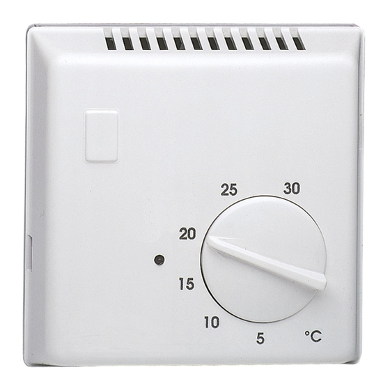
Présentation du produit
réf. 25614 : avec contact inverseur et entrée
horloge pour abaissement de tem-
pérature (réglable de -3K à – 7K à
l'aide du potentiomètre situé en
haut à gauche, préréglage – 3K)
réf. 25615 : avec contact à ouverture et inter-
rupteur marche/arrêt
réf. 25620 : avec contact inverseur
réf. 25800 : avec contact à ouverture et voyant
réf. 25805 : idem 25614 mais avec réglage de
la consigne de température sous le
couvercle
réf. 25809 : avec contact à ouverture
Socle
1
Disque
2
Ergot de limitation d'échelle à détacher du
3
socle du thermostat (sauf 25800 et 25809).
Ils se trouvent dans les trous de fixation
Bouton
4
Couvercle
5
Emplacements pour ergots de limitation
6
d'échelle
Installation
le thermostat d'ambiance doit être monté à
environ 1,5 mètre du sol, sur un mur intérieur,
à l'abri du rayonnement solaire direct et de
toute perturbation thermique telle que lampe
d'éclairage, téléviseur, tuyau de chauffage,
cheminée, télévision, courant d'air etc.
Schéma de raccordement
Veuillez respecter le schéma de raccordement
qui se trouve à l'intérieur du couvercle
Ajustement de l'échelle
de température
Deux jours environ après l'installation, relevez la
température ambiante à l'aide d'un thermomètre
de référence placé au centre de la pièce. Retirez
le bouton
puis repositionnez-le de manière à
4
ce que la flèche indique la même température
que celle indiquée par le thermomètre.
OK
1,50 m
1
a Thermostats d'ambiance bi-métal
z Bimetallic room thermostats
e Bimetall-Raumthermostate
User instructions
Z
Product presentation
ref. 25800 : with normally-closed contact and hea-
ting indicator
ref. 25615 : with normally-closed contact and ON/
OFF switch.
ref. 25620 : with changeover contact
ref. 25614 : with changeover contact and program-
mable setpoint reduction by means of a
separate timer (variable from – 3K to –
7K, works setting : – 3K)
ref. 25805 : same as 25614 but temperature
adjustement under the cover.
ref. 25809 : with normally-closed contact
Base
1
Disk
2
Lock pins (except 25800 and 25809). The lock
3
pins for the scale limitation are to be detached
from the base. They are located on the fixing
holes.
Knob
4
Cover
5
Site for the lock pins
6
.
5
(
25800/25809)
Installation
The room thermostat must be installed at approxi-
mately 1,5 metre up from floor upon an interior wall,
away from direct solar radiation and any heat
source such as television, lighting and air draught
etc.
Connection
Connect all leads as shown in circuit diagram in
cover
.
5
Temperature's range limitation
After two days from the installation, measure the
room temperature with a reference thermometer.
Draw back the knob
same value of the reference thermometer.
sauf/except/außer
and locate it to reach the
4
I
0
Bedienungsanleitung
E
Produktbeschreibung
Art. Nr. 25614 : mit Wechsel-Kontakt und
Schaltuhren Eingang für
Temperaturabsenkung,
(regelbar von – 3K bis – 7K
durch Potentiometer oben links,
Werkeinstellung – 3K)
Art. Nr. 25615 : mit Öffner-Kontakt und Ein-Aus
Schalter
Art. Nr. 25620 : mit Wechsel-Kontakt
Art. Nr. 25800 : mit Öffner-Kontakt und Kontrol-
lampe
Art. Nr. 25805 : wie 25614 aber mit
Temperatureinstellung unter
dem Gehäusedeckel.
Art. Nr. 25809 : mit Öffner-Kontakt
Sockel
1
Scheibe
2
Bereichseinstellungsstifte müssen vom Sockel
3
gelöst werden (außer 25800 und 25809).
Sie befinden sich in den Befestigungslöchern
Knopf
4
Deckel
5
Löcher für Bereichseinstellungsstifte
6
Installation
Das Raumtemperaturthermostat sollte in 1,5
m. Höhe über Boden an einer Innenwand,
geschützt vor direkter Sonneneinstrahlung und
Wärmequellen aller Art wie Lampe, Fernseher,
Heizkörper sowie vor störendem Luftzug usw.
eingebaut werden.
Anschluß
Schliessen Sie alle Leitungen genau nach dem
Schaltbild im Gehäusedeckel
5
Einstellung der Temperaturskala
Um eine präzise Einstellung der Skala zu
erhalten, wird empfohlen, ca zwei Tage nach
dem Einbau die Raumtemperatur mit einem
Thermometer zu messen. Den Knopf
ziehen und ihn neu positionieren damit der Pfeil
die gleiche Temperatur wie das Thermometer
anzeigt.
∞
3 0
2 5
2 0
° C
1 5
1 0
5
an.
zurück-
4
6LE000438B
Werbung

Verwandte Anleitungen für hager flash 25620


Inhaltszusammenfassung für hager flash 25620
- Seite 1 a Thermostats d’ambiance bi-métal z Bimetallic room thermostats e Bimetall-Raumthermostate ° C 25620 - 25615 - 25614 25809 - 25805 - 25800 Notice d’instruction User instructions Bedienungsanleitung Présentation du produit Product presentation Produktbeschreibung réf. 25614 : avec contact inverseur et entrée ref.
- Seite 2 Verwendbar in ganz Europa M und in der Schweiz Hager SAS - 132 bld d’Europe - BP 78 - 67 212 Obernai cedex (FRANCE) - Tél. +333 88 49 50 50 - www.hager- Hager Controls S.A.S., 33 rue Saint-Nicolas, B.P. 10140, 67703 SAVERNE CEDEX, France - www.hager.com Hager 09.2017 - 6LE000438B...