Velleman KSR6 Bedienungsanleitung
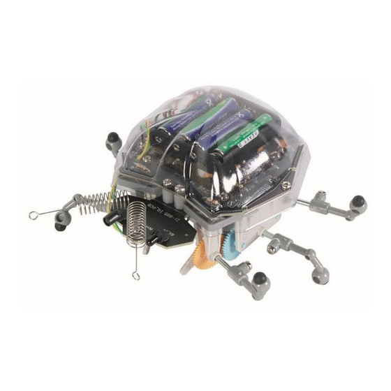
"ladybug" robot kit

Verwandte Anleitungen für Velleman KSR6


Inhaltszusammenfassung für Velleman KSR6
- Seite 1 KSR6 "LADYBUG" ROBOT KIT NEDERLANDS FRANÇAIS ESPAÑOL DEUTSCH PORTUGUÊS POLSKI USER MANUAL GEBRUIKERSHANDLEIDING MODE D’EMPLOI MANUAL DEL USUARIO BEDIENUNGSANLEITUNG INSTRUKCJA OBSŁUGI MANUAL DO UTILIZADOR...
-
Seite 2: General Guidelines
The KSR6 uses infrared emitting diodes as "eyes" to avoid obstacles in its path. The Ladybug automatically makes a left turn when it detects an object. It continues to move forward as long as there's no detection. -
Seite 3: Mechanical Parts List
KSR6 Mechanical Parts List 1. 2x screw 3x6mm (P13) 2. 9x screw 3x6mm (P14) 3. 3x nut M3 (P15) 4. 4x hex post 10mm (P16) 5. 1x body (P17) 6. 2x antenna (P18) Fig. 2 Assembly PCB Assembly Start the assembly by mounting the resistors. The names of all components have been printed on the PCB:... -
Seite 4: Gearbox Assembly
KSR6 Mount the IR emitting diode, the photo transistor and the female header (fig. 3a and 3b). Part ID Description Quantity TX_IR IR emitting diode (fig. 1 #4) RX_IR photo transistor (fig. 1 #5) From Main_Board female header (fig. 1 #9) Gearbox Assembly Parts (fig. - Seite 5 KSR6 Assembly V. 02 – 09/02/2018 ©Velleman nv...
-
Seite 6: Mechanical Assembly
KSR6 Mechanical Assembly 1. Mount the wires and the ceramic capacitors type 104 on the motors and fix the antennae on the small PCB. The colour code used for the wires is: 1=green, 2=yellow, 3=orange, 4=blue (fig. 6 and 7). - Seite 7 KSR6 4. Connect the wires to the pins on the M-terminals (fig. 10): 5. Mount the body to the rest of the KSR6 (fig. 11). Wiring Diagram (fig. 12) V. 02 – 09/02/2018 ©Velleman nv...
-
Seite 8: Operation
3. The sensitivity may be affected by fading battery power. Adjust the variable resistor to improve the range. 4. Apply a little bit of machine oil to the axles of the gears if the KSR6 isn't running smoothly. Use this device with original accessories only. Velleman nv cannot be held responsible in the event of damage or injury resulting from (incorrect) use of this device. -
Seite 9: Gebruikershandleiding
De KSR6 maakt gebruik van infrarood-diodes als 'ogen' om obstakels op zijn weg te omzeilen. De Ladybug draait automatisch naar links wanneer het een voorwerp detecteert. Het blijft vooruit bewegen zolang er geen detectie is. -
Seite 10: Montage
KSR6 Lijst van mechanische onderdelen (zie fig. 2) 1. 2 x schroef 3 x 6mm (P13) 2. 9x schroef 3 x 6mm (P14) 3. 2 x moer M3 (P15) 4. 2 x hexag. afstandsbus 10mm (P16) 5. 2 x behuizing (P17) 6. - Seite 11 KSR6 To IR_PCB pinheader (fig. 1 #8) Monteer de IR diode, de fototransistor en de vrouwelijke pinheader: (zie figuren 3a en 3b op blz. 2) Part ID Beschrijving Hoev. TX_IR IR diode (fig. 1 #4) RX_IR fototransistor (fig. 1 #5) From Main_Board vrouwelijke pinheader (fig.
-
Seite 12: Mechanische Montage
4. Smeer wat fijne machineolie op de assen van de tandwielen als de KSR6 niet soepel loopt. Gebruik dit toestel enkel met originele accessoires. Velleman nv is niet aansprakelijk voor schade of kwetsuren bij (verkeerd) gebruik van dit toestel. -
Seite 13: Directives Générales
Si l’appareil a été endommagé pendant le transport, ne pas l’installer et consulter votre revendeur. Le KSR6 a des 'yeux' diodes IR lui permettant de contourner des obstacles dans sa route. Le Ladybug tourne automatiquement à gauche quand il détecte un objet. Il continue en avant tant qu'il n'y a pas de détection. - Seite 14 KSR6 4. 4x entretoise hexagonale 10mm (P16) 5. 1x boîtier (P17) 6. 2x antenne (P18) Montage Montage du CI Montez d'abord les résistances. Les noms des composants sont imprimés sur le CI. Pièce Description Couleur Qté. 10Ω brun/noir/noir/doré R12/17 15Ω...
-
Seite 15: Montage Mécanique
1. Mettez l'interrupteur dans la position “ON”. 2. Mettez le KSR6 sur le sol ; il commencera à bouger en avant. 3. Quand il détecte un obstacle, il tourne automatiquement à gauche. S'il n'y a pas d'obstacle, il continue tout droit. -
Seite 16: Problèmes Et Solutions
3. La sensibilité peut diminuer quand les piles deviennent faibles. Augmentez la portée avec la résistance variable. 4. Lubrifiez les axes des pignons avec un peu d'huile de graissage fine si votre KSR6 ne bouge pas aisément. N’employer cet appareil qu’avec des accessoires d’origine. La SA Velleman ne peut, dans la mesure conforme au droit applicable être tenue responsable des dommages ou lésions (directs ou indirects) -
Seite 17: Manual Del Usuario
Si el aparato ha sufrido algún daño en el transporte no lo instale y póngase en contacto con su distribuidor. El KSR6 utiliza diodos de emisión IR como "ojos" para evitar obstáculos. El "Ladybug" gira automáticamente a la izquierda al detectar un obstáculo. Avanza siempre en línea recta mientras no haya obstáculo. -
Seite 18: Montaje
KSR6 Lista de piezas mecánicas (véase fig. 2) 1. 2x tornillo 3 x 6mm (P13) 2. 9x tornillo 3 x 6mm (P14) 3. 3x tornillo M3 (P15) 4. 4x separador hexagonal 10mm (P16) 5. 1x caja (P17) 6. 2x antena (P18) - Seite 19 KSR6 To IR_PCB conector (fig. 1 #8) Monte el diodo IR, el fototransistor y el conector hembra: (véase figuras 3a y 3b) Pieza Descripción Cantidad TX_IR diodo IR (fig.1 #4) RX_IR fototransistor (fig.1 #5) From Main_Board conector hembra (fig.1 #9) Montaje de la caja de engranajes Partes (véase fig.
-
Seite 20: Solución De Problemas
3. La sensibilidad puede disminuir si las pilas se debilitan. Aumente el alcance con la resistencia variable. 4. Lubrique los ejes de los piñones con un poco de aceite fino de máquina si el KSR6 no se mueve de forma flexible. -
Seite 21: Allgemeine Richtlinien
Überprüfen Sie, ob Transportschäden vorliegen. Sollte dies der Fall sein, verwenden Sie das Gerät nicht und wenden Sie sich an Ihren Händler. Der KSR6 verwendet Infrarot-Dioden als 'Augen' um Hindernisse zu umgehen. Der 'Ladybug' dreht automatisch nach links wenn er ein Objekt detektiert. Er geht immer geradeaus solange er nichts detektiert. -
Seite 22: Liste Der Mechanischen Teile (Siehe Abb. 2)
KSR6 Liste der mechanischen Teile (siehe Abb. 2) 1. 2 x Schraube 3 x 6mm (P13) 2. 9x Schraube 3 x 6mm (P14) 3. 2 x Mutter M3 (P15) 4. 2 x hexag. Abstandbuchse 10mm (P16) 5. 2 x Gehäuse (P17) 6. - Seite 23 KSR6 To IR_PCB Stiftleiste (Abb. 1 #8) Montieren Sie die IR-Diode, den Fototransistor und die Buchsenleiste: (siehe Abb. 3a und 3b). Teil Beschreibung Menge TX_IR IR-Diode (Abb. 1 #4) RX_IR Fototransistor (Abb. 1 #5) From Main_Board Buchsenleiste (Abb. 1 #9) Montage Zahnradkasten Teile (siehe Abb.
-
Seite 24: Probleme Und Lösungen
3. Die Empfindlichkeit kann durch schwächere Batterien beeinflusst werden. Stimmen Sie den regelbaren Widerstand ab um die Empfindlichkeit zu vergrößern. 4. Schmieren Sie die Achsen der Zahnräder mit feinem Maschinenöl wenn der KSR6 nicht störungsfrei läuft. Verwenden Sie dieses Gerät nur mit originellen Zubehörteilen. Velleman NV übernimmt keine Haftung für Schaden oder Verletzungen bei (falscher) Anwendung dieses Gerätes. -
Seite 25: Instrukcja Obsługi
W razie wątpliwości należy skontaktować się z lokalnym organem odpowiedzialnym za utylizację odpadów. Dziękujemy za zakup produktu Velleman! Prosimy o dokładne zapoznanie się z instrukcją obsługi przed użyciem urządzenia. Nie montować ani nie używać urządzenia, jeśli zostało uszkodzone podczas transportu - należy skontaktować... - Seite 26 KSR6 Lista części mechanicznych (rys. 2) 1. 2x śruba 3x6mm (P13) 2. 9x śruba 3x6mm (P14) 3. 3x nakrętka M3 (P15) 4. 4x tulejka dystansowa 6-kątna 10 mm (P15) 5. 1x obudowa (P17) 6. 2x czułek (P18) Montaż Montaż płytki drukowanej Montaż...
- Seite 27 KSR6 Zmontować diodę emitującą podczerwień, fototranzystor i listwę żeńską (rys. 3a i 3b). ID części Opis Ilość TX_IR dioda emitująca podczerwień IR (rys. 1, nr RX_IR fototrazystor (rys. 1, nr 5) From Main_Board listwa żeńska (rys. 1, nr 9) Montaż przekładni Części (rys.
-
Seite 28: Wykrywanie I Usuwanie Usterek
3. Na czułość może mieć wpływ spadek mocy baterii. Wyregulować reostat, aby poprawić zasięg. 4. Jeśli KSR6 nie porusza się płynnie, należy nałożyć odrobinę oleju maszynowego na osie kół zębatych. Należy używać wyłącznie oryginalnych akcesoriów. Firma Velleman nv nie ponosi odpowiedzialności za uszkodzenia lub urazy wynikające z (niewłaściwego) korzystania z niniejszego urządzenia. -
Seite 29: Manual Do Utilizador
Caso o aparelho tenha sofrido algum dano durante o transporte não o instale e entre em contacto com o seu distribuidor. O KSR6 utiliza diodos emissores de infravermelhos como "olhos" para evitar os obstáculos que se atravessam no seu caminho. O Ladybug (Joaninha) vira automaticamente à esquerda assim que detecta um objecto. - Seite 30 KSR6 Lista das Peças Mecânicas (fig. 2) 1. 2x parafuso 3x6mm (P13) 2. 9x parafuso 3x6mm (P14) 3. 3x porca M3 (P15) 4. 4x poste hexagonal 10mm (P16) 5. 1x corpo (P17) 6. 2x antena (P18) Montagem Montagem da Placa de Circuitos Internos (PCB) Inicie a montagem começando por instalar os resistores.
- Seite 31 KSR6 Conector Berg (fig. 1 #8) para IR_PCB Monte o diodo emissor de infravermelhos (IR), o fototransistor e o conector Berg fêmea (fig. 3a e 3b). ID da peça descrição quantidade TX_IR diodo emissor de infravermelhos (IR) (fig. 1 #4) RX_IR fototransistor (fig.
-
Seite 32: Resolução De Problemas
3. A sensibildiade pode ser afectada pela falta de potência da bateria. Regule o resistor variável para aumentar o alcance. 4. Aplique um pouco de lubrificante nos eixos das engrenagens caso o KSR6 não esteja a funcionar perfeitamente. Utilize este aparelho apenas com acessórios originais. A Velleman NV não será responsável por quaisquer danos ou lesões causados pelo uso (indevido) do aparelho. - Seite 33 Velleman®; worden. - se calcula gastos de transporte de y a Velleman® si el aparato ya no está • Bij reparaties buiten de waarborgperiode zullen transportkosten aangerekend cubierto por la garantía.
- Seite 34 Velleman® Service- und Qualitätsgarantie wymienione wyżej warunki są bez uszczerbku dla wszystkich komercyjnych gwarancji. Seit der Gründung in 1972 hat Velleman® sehr viel Erfahrung als Verteiler in der Powyższe postanowienia mogą podlegać modyfikacji w zależności od Elektronikwelt in über 85 Ländern aufgebaut.