Inhaltsverzeichnis
Werbung
Verfügbare Sprachen
Verfügbare Sprachen
Werbung
Inhaltsverzeichnis

Verwandte Anleitungen für Rizzoli RI


Inhaltszusammenfassung für Rizzoli RI
- Seite 1 Istruzioni d’uso • Gebrauchsanweisung Instructions • Manuel d’utilisation...
- Seite 3 ITALIANO Disposizioni Installazione Manutenzione Cosa fare se... Dati tecnici Garanzia DEUTSCH Anweisungen Montage Gebrauch Wartung Was tun, wenn... Technische daten Garantie ENGLISH Instructions Installation Maintenance What to do if... Technical data Warranty FRANÇAIS Dispositions Installation Utilisation Entretien Que faire si... Donnees techniques Garantie...
-
Seite 4: Disposizioni Generali
La Vostra scelta è caduta su una cucina Rizzoli frutto di sempre senza perdere di vista l’eleganza, la bellezza e la una tradizione che ha origine nel lontano 1912 quando funzionalità... -
Seite 5: Combustibile Raccomandato
COMBUSTIBILE RACCOMANDATO Le cucine a legna sono espressamente costruite rifica nominale ed evita la produzione eccessiva per la combustione di legna da ardere di qualsiasi di residui carboniosi e fuliggine. Per evitare pos- tipo. Si consiglia di utilizzare legna di buona qua- sibili deformazioni o danneggiamenti della cucina lità, secca e ben stagionata;... - Seite 6 17 Piastra 6 Battifiamma 12 Leva di apertura porta 18 Disco o cerchi ACCESSORI In dotazione alle cucine a legna Rizzoli sono pre- zione, la manutenzione e l’uso quotidiano. senti alcuni accessori che semplificano l’installa- • Cassetto cenere • Griglia per il forno (modelli con forno) •...
- Seite 7 INSTALLAZIONE AVVERTENZE Le cucine a legna Rizzoli sono di facile installazio- del camino e la possibilità di effettuare gli allaccia- ne; vanno comunque osservate alcune precauzioni menti necessari. Per lo spostamento della cucina per evitare danneggiamenti dovuti a imperizia. Pri- evitate di trascinarla, ma spostatela sempre stac- ma dell’installazione raccomandiamo di verificare...
- Seite 8 Figura 3 – Distanze minime di sicurezza in abbinamento ad appositi distanziali per l’inserimento ad incasso delle cucine serie RE - RVE in prossimità di materiale infiammabile. DISTANZE DI SICUREZZA (RI – RVI) Le cucine a legna serie RI - RVI sono state studia- Si devono comunque rispettare le distanze minime te appositamente per l’inserimento ad incasso tra i sia per la dilatazione termica dei materiali (1-2 mm) mobili.
- Seite 9 CAMINO Il camino è di vitale importanza per il corretto fun- funzionamento della cucina. Per la costruzione del zionamento di una cucina a legna. Le cucine a legna camino è obbligatorio l’utilizzo di materiali adatti sono studiate per garantire il massimo rendimento, a resistere ad alta temperatura e rispondenti alle però...
- Seite 10 Più è alto il camino e maggio- scorretta realizzazione del camino. re è il tiraggio, se l’altezza del camino è inferiore a RE - RVE RE - RVE Modello RI - RVI RI - RVI senza forno con forno 130 mm 130 mm ø...
- Seite 11 RACCORDO O CANALE DA FUMO Il raccordo di collegamento tra la cucina e la canna non deve entrare all’interno della canna fumaria. fumaria, detto anche canale da fumo, deve essere Per rendere più sicuro il raccordo si consiglia di il più corto possibile e non deve presentare tratti installare sul muro un rosone accertandosi che il orizzontali o scarsamente inclinati.
- Seite 12 SERIE RE - RVE con forno Figura 9 – Cucina multifumo con forno, predisposizione dell’uscita fumi corretta. 2.11 CORRETTO ALLACCIAMENTO AL CAMINO Se la canna fumaria parte dal piano inferiore ri- inserito e quindi girato in modo da restare bloc- spetto al punto di collegamento della cucina può cato. Questo connettore permette una tolleranza essere necessario chiudere la canna fumaria al di di circa 1 cm in modo da facilitare l’installazione.
- Seite 13 2.12 USCITA FUMI POSTERIORE REGOLABILE (CUCINE SENZA FORNO) Su tutti i modelli senza forno è possibile modificare richiesta Rizzoli è in grado di fornire una lamiera l’uscita fumi da destra a sinistra e viceversa. Inoltre aggiuntiva per poter utilizzare l’uscita fumi nelle è possibile anche variare la posizione in orizzontale posizioni intermedie della lamiera (vedi fig.
- Seite 14 Lo spostamento si sviluppa do la lamiera (vedi fig. 14b). Su richiesta Rizzoli è in sia orizzontalmente sia verticalmente, in modo da grado di fornire una lamiera aggiuntiva per poter potersi meglio adattare all’installazione del tubo...
- Seite 15 LAMIERA STANDARD Modello standard RE 60 - RVE 60 RE 80 - RVE 80 RE 90 - RVE 90 RI 70 - RVI 70 RI 90 - RVI 90 RI 100 - RVI 100 Tabella 3a – Distanza minima e massima del centro foro dell’uscita fumi. Non tiene in considerazione la Figura 14a – Vista posteriore della cucina tolleranza dovuta all’attacco a baionetta...
- Seite 16 Per fare questo è necessario predisporre un con- La presa d’aria del locale deve avere una superficie dotto collegato direttamente con l’esterno dell’a- minima di 80 cm². Su richiesta Rizzoli può fornire bitazione e effettuarne il collegamento diretto con delle valvole studiate appositamente per permet- la presa d’aria della cucina.
- Seite 17 RE 60 - RVE 60 RE 80 - RVE 80 Ingresso aria esterna RE 90 - RVE 90 RE 100 - RVE 100 RI 60 - RVI 60 Figura 17 – Vista posteriore dello zoccolo della cuci- na a legna e specifiche per il collegamen- RI 70 - RVI 70 to con la presa d’aria esterna. RI 90 - RVI 90...
-
Seite 18: Collegamenti Elettrici
2.15 COLLEGAMENTI ELETTRICI Il collegamento elettrico delle cucine serve per collegare un cavo elettrico alla morsettiera posta azionare le ventole sui fianchi e, nei modelli con nel retro della cucina. Devono essere effettuati i forno, anche per l’alimentazione della lampadina corretti collegamenti di linea, neutro e terra come del forno. - Seite 19 2.16 ESTRAZIONE CASSA PORTA LEGNA Per la rimozione della cassa porta legna occorre re ed estrarre. Per rimettere in posizione la cassa estrarre la cassa fino a fine corsa, togliere le due porta legna ripetete le operazioni in senso inverso, viti a galletto che la tengono fissata alle strade prestando attenzione ad inserire correttamente la scorrevoli.
- Seite 20 Figura 22 – Regolazione della rientranza dello zoccolo rispetto al corpo della cucina. 2.18 REGOLAZIONE DELLO ZOCCOLO TELESCOPICO Le cucine a legna possono essere dotate su ri- maggiorata integrata nello zoccolo. In questo caso chiesta di una speciale cassa porta legna di misura è comunque possibile la regolazione dell’altezza 10 mm...
-
Seite 21: Prima Accensione
dello zoccolo, ma non la regolazione della rien- da coprire la parte scoperta: per fare questo si de- tranza che, in questo caso, è fissa a 70 mm. Misure vono togliere le 2 viti come in figura 23A e 23B. diverse sono possibili, ma vanno preventivamente Successivamente si deve regolare anche l’altezza concordate in fase di ordine. - Seite 22 FUNZIONAMENTO DELLA CUCINA A LEGNA Durante il funzionamento, all’interno della cucina ga in più punti diversi per ottenere la massima effi- avviene una reazione di combustione tra il combu- cienza. In particolare è presente una alimentazione stibile (la legna inserita nella camera di combustio- di aria primaria, che affluisce nella parte inferiore ne) e il comburente (l’ossigeno presente nell’aria della camera di combustione attraverso la griglia,...
-
Seite 23: Regolazione Dell'aria
in questo modo si ottiene un miglioramento del teorologiche. Non appena il fuoco ha preso vigore tiraggio. si deve richiudere la chiave in modo da forzare Per accendere il fuoco potete utilizzare come com- il fumo a riscaldare tutte le parti della cucina. La bustibile legna ben secca, spaccata molto sottile, cucina è... - Seite 24 Figura 25 – Regolazione della leva della presa d’aria. Figura 26 – Regolazione dell’aria primaria e secon- La valvola è aperta in corrispondenza daria. Il regolatore si apre ruotando la della posizione indicata con la lettera “A”, manopola in senso orario. mentre è chiusa nella posizione indicata con la lettera “B”. ATTENZIONE! Nel caricare la legna si raccomanda di mantenere una distanza di alcuni centimetri tra il vetro della porta fuoco e il combustibile, in modo da non esporre il vetro a temperature eccessive che lo potrebbero danneggiare. COTTURA SULLA PIASTRA La piastra radiante in acciaio è espressamente stu- cibi caldi. Per ottenere la massima velocità nella diata per permettere di cucinare in modo sempli- cottura occorre utilizzare legna spaccata sottile ed ce e rapido.
-
Seite 25: Illuminazione Del Forno
VALVOLA PER L’ECCESSO DI VAPORE La cottura di pietanze in taluni casi può compor- tare la formazione di un eccesso di vapore all’in- terno del forno di cottura. Sui modelli con forno è presente una valvola per eliminare l’eccesso di vapore. - Seite 26 VENTOLE Le cucine sono dotate di serie di ventilazione for- zata sui fianchi. Questi modelli sono in grado di produrre una parte di calore per convezione. Con questo dispositivo viene prelevata aria fredda dal- lo zoccolo della cucina, viene fatta scorrere forza- tamente attraverso i fianchi e nella parte superiore e posteriore della cucina, infine viene espulsa dai fori disposti sul piano e su altre parti della cuci-...
- Seite 27 3.11 TEGLIA CON GUIDE SCORREVOLI Su tutte le cucine con forno è in dotazione un si- una sola posizione all’interno del forno, ma questa stema a guida scorrevole di supporto per la teglia. può essere modificata, portandola nella posizione In questo modo è possibile estrarre completamen- più...
- Seite 28 3.12 PORTATEGLIA In dotazione alla cucina è presente un dispositivo utilizzare delle presine o degli stracci. Il portate- portateglia che permette di estrarre la teglia dal glia va agganciato al bordo della teglia e utilizzato forno caldo in tutta sicurezza senza la necessità di a due mani.
- Seite 29 Asciugate con un lizia approfondita farà tornare tutto come nuovo. panno morbido, muovendolo nel senso della sa- Su richiesta Rizzoli fornisce degli specifici prodotti tinatura. Per le parti smaltate o verniciate evitate per la pulizia dell’acciaio inox. Si raccomanda an- l’uso di abrasivi e di detersivi aggressivi o acidi.
-
Seite 30: Pulizia Del Forno
ISPEZIONE GIROFUMI Nelle cucine con forno i fumi di combustione sono forzati a girare completamente attorno al forno. Per questo motivo le cucine con forno sono dotate di una apertura di ispezione per effettuare la pu- lizia del percorso girofumi. La pulizia deve essere effettuata almeno una volta ogni sei mesi di uso normale della cucina come per la pulizia del cami- no, a seconda dell’uso potrebbe essere necessaria... - Seite 31 PULIZIA DEL CAMINO La pulizia del camino va effettuata da parte di per- Tutte le parti del camino devono essere pulite. In sonale specializzato almeno una volta ogni sei mesi concomitanza con la pulitura del camino procede- di uso normale della cucina. La pulizia deve essere te anche alla pulizia interna della cucina asportan- fatta comunque ogni qualvolta si renda necessario do la piastra e pulendo la parte superiore del forno...
-
Seite 32: Manutenzione Straordinaria
In questo caso può essere sostituita con del vetro coprilampada della lampadina del forno. una lampadina con le stesse caratteristiche tecni- Per fare questo dovete svitare il coprilampada, ri- che (lampadina alogena 25W 230V 300 °C attacco muovere i depositi esterni dovuti ai fumi di cottu- G9). - Seite 33 COSA FARE SE... Problemi Effetti Possibili rimedi • Verificare che tutte le regolazioni dell’aria siano nella loro posizione di massima apertura • Ve- rificare che cenere e residui non ostruiscano la griglia • Verificare che la griglia non sia montata alla rovescia (la parte piana va rivolta verso l’alto) •...
- Seite 34 DATI TECNICI DATI TECNICI SERIE RE - RVE SENZA FORNO RE 40 RE 45 RE 50 Modello RVE 40 RVE 45 RVE 50 Peso 120 kg 140 kg 150 kg Potenza nominale 7,4 kW 7,4 kW 7,4 kW Rendimento 80,8 % 80,8 % 80,8 % Emissioni CO (13% O2)
-
Seite 35: Distanze Di Sicurezza
EMISSIONI SECONDO BIMSCHV RE 40 RE 45 RE 50 Modello BImSchV RVE 40 RVE 45 RVE 50 Potenza nominale 7,4 kW 7,4 kW 7,4 kW Rendimento 80,8 % 80,8 % 80,8 % > 70 % Emissioni CO (13% O2) 845 mg/m3 845 mg/m3 845 mg/m3 <... - Seite 36 DATI TECNICI SERIE RE - RVE CON FORNO RE 60 RE 80 RE 90 RE 100 Modello RVE 60 RVE 80 RVE 90 RVE 100 Peso 165 kg 180 kg 209 kg 230 kg Potenza nominale 7,5 kW 8,0 kW 8,0 kW 8,0 kW Rendimento 74,3 %...
- Seite 37 EMISSIONI SECONDO BIMSCHV RE 60 RE 80 RE 90 RE 100 BImSchV Modello RVE 60 RVE 80 RVE 90 RVE 100 Potenza nominale 7,5 kW 8,0 kW 8,0 kW 8,0 kW Rendimento 74,3 % 86,4 % 86,4 % 86,4 % > 70 % Emissioni CO (13% O2) 1413 mg/m3 631 mg/m3...
- Seite 38 6.11 DATI TECNICI SERIE RI - RVI RI 60 RI 70 RI 90 RI 100 Modello RVI 60 RVI 70 RVI 90 RVI 100 Peso 170 kg 177 kg 207 kg 217 kg Potenza nominale 7,4 kW 7,5 kW 8,0 kW...
- Seite 39 Distanze di sicurezza da materiale infiammabile o sensibile al calore in assenza di sistemi di isolamento aggiuntivi. Modello Lateralmente Dietro Davanti Sopra RI 60 - RVI 60 0,1 cm 45 cm 100 cm 60 cm RI 70 - RVI 70 0,1 cm...
-
Seite 40: Parti Non Incluse In Garanzia
La ditta Rizzoli, a proprio insindacabile giudizio Per le riparazioni presso i Centri di Assistenza della deciderà se la prestazione di garanzia debba essere ditta Rizzoli il cliente è tenuto a versare le spese fatta in loco oppure presso i propri stabilimenti. di trasporto. - Seite 41 TRIBUNALE COMPETENTE Per qualsiasi controversia o contestazione sarà com- petente sempre e solo il foro di Bolzano. Avvertenza Rizzoli S.r.l. è costantemente impegnata nel migliorare i propri prodotti, per questo il contenuto del presente libretto di istruzioni può cambiare senza preavviso.
-
Seite 42: Dichiarazione Di Prestazione
Usi previsti del prodotto conformemente Riscaldamento e cottura alla relativa specifica tecnica armonizzata uso domestico Nome o marchio registrato del fabbricante (art. 11-5) Rizzoli s.r.l. Nome e indirizzo del mandatario Sistema di valutazione e verifica della costanza System 3 della prestazione (allegato 5) Laboratorio notificato ACTECO S.r.l. - Seite 43 Usi previsti del prodotto conformemente Riscaldamento e cottura alla relativa specifica tecnica armonizzata uso domestico Nome o marchio registrato del fabbricante (art. 11-5) Rizzoli s.r.l. Nome e indirizzo del mandatario Sistema di valutazione e verifica della costanza System 3 della prestazione (allegato 5) Laboratorio notificato Kiwa Italia s.p.a.
- Seite 44 Usi previsti del prodotto conformemente Riscaldamento e cottura alla relativa specifica tecnica armonizzata uso domestico Nome o marchio registrato del fabbricante (art. 11-5) Rizzoli s.r.l. Nome e indirizzo del mandatario Sistema di valutazione e verifica della costanza System 3 della prestazione (allegato 5) Laboratorio notificato ACTECO S.r.l.
- Seite 45 Ai sensi dei regolamenti prodotti da costruzione n. 305/2011 N.92 Codice di identificazione unico del Prodotto-tipo RE 50 Modello e/o n. serie (art. 11-4) RI 60 - RVI 60 Usi previsti del prodotto conformemente Riscaldamento e cottura alla relativa specifica tecnica armonizzata uso domestico Nome o marchio registrato del fabbricante (art. 11-5) Rizzoli s.r.l.
- Seite 46 Ai sensi dei regolamenti prodotti da costruzione n. 305/2011 N.93 Codice di identificazione unico del Prodotto-tipo RA 60 CF Modello e/o n. serie (art. 11-4) RI 70 - RVI 70 Usi previsti del prodotto conformemente Riscaldamento e cottura alla relativa specifica tecnica armonizzata uso domestico Nome o marchio registrato del fabbricante (art. 11-5) Rizzoli s.r.l.
- Seite 47 Ai sensi dei regolamenti prodotti da costruzione n. 305/2011 N.94 Codice di identificazione unico del Prodotto-tipo RVE 80 Modello e/o n. serie (art. 11-4) RI 90 - RI 100 RVI 90 - RVI 100 Usi previsti del prodotto conformemente Riscaldamento e cottura alla relativa specifica tecnica armonizzata uso domestico Nome o marchio registrato del fabbricante (art.
- Seite 48 Accessori pag. INSTALLAZIONE pag. Avvertenze pag. Accorgimenti per l’installazione pag. Distanze di sicurezza (RE - RVE) pag. Distanze di sicurezza (RI - RVI) pag. Camino pag. Dimensioni e forme corrette del camino pag. Canna fumaria pag. Comignolo pag. Raccordo o canale da fumo pag.
- Seite 49 Emissioni secondo 15a B-VG pag. Emissioni secondo BImSchV pag. Distanze di sicurezza pag. 6.10 Regolazioni alla potenza nominale pag. 6.11 Dati tecnici Serie RI - RVI pag. 6.12 Emissioni secondo 15a B-VG pag. 6.13 Emissioni secondo BImSchV pag. 6.14 Distanze di sicurezza pag.
- Seite 50 INDICE Modalità di garanzia pag. Vizi o errori nei materiali pag. Parti non incluse in garanzia pag. Prestazioni fuori garanzia pag. Responsabilità pag. Tribunale competente pag. Dichiarazione di prestazione n. 82 pag. Dichiarazione di prestazione n. 91 pag. Dichiarazione di prestazione n. 83 pag.
-
Seite 52: Anweisungen
Die Verwendung ökonomischer und umweltfreundlicher Jahr 1912 zurückgeht, als Carlo Rizzoli mit der Her- Brennstoffe, die behagliche Wärme des natürlichen stellung von Holzherden im typischen Stil der Dolomi- Feuers und der angenehme Duft des aus unseren Wäldern tentäler begann. Mit der Zeit hat Rizzoli seine Produkte... -
Seite 53: Empfohlener Brennstoff
EMPFOHLENER BRENNSTOFF Rizzoli-Holzherde sind ausdrücklich zur Verwen- gleichzeitig die Bildung von Kohlenstoffrückstän- dung von Brennholz bestimmt. Es wird empfohlen, den und Ruß. Um eventuelle Verformungen oder qualitativ gutes, luftgetrocknetes, nach Möglich- Beschädigungen des Herdes zu vermeiden, sollte keit gespaltenes Kleinholz zu verwenden. Die Ver- auf keinen Fall übermäßig viel Brennholz aufgelegt... -
Seite 54: Zubehör
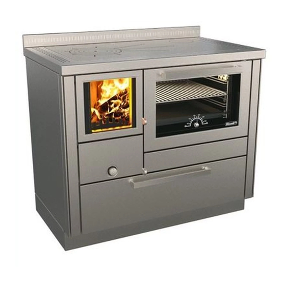
11 Holzlade 17 Herdplatte 6 Flammenschutz 12 Türöffnungshebel 18 Einlegeplatte oder Ringe ZUBEHÖR Im Lieferumfang der Rizzoli-Holzherde sind einige und den täglichen Gebrauch des Herdes erleich- Zubehörteile enthalten, die die Montage, Wartung tern. • Aschekasten • Backofenrost (Modelle mit Backofen) • Schutzhandschuh (Modelle RVE - RVI) •... -
Seite 55: Montage
MONTAGE ANWEISUNGEN Rizzoli-Holzherde sind problemlos und einfach zu rechte Ausführung des Schornsteins und die Mög- montieren. Folgende Vorsichtsmaßnahmen zur lichkeit zur Vornahme der nötigen Anschlüsse. Bei Vermeidung eventueller Schäden aufgrund von Standortveränderung den Herd nicht verschieben, Unerfahrenheit sind zu beachten: Kontrollieren Sie sondern anheben und verstellen. -
Seite 56: Sicherheitsabstände (Re - Rve)
60 cm Abb. 3 - Mindestsicherheitsabstände für den Einbau, mit eigens dazu bestimmten Abstandsverbindungen zum Einbau der Holzherde Serie RE - RVE neben hitzeempfindlichen Materialien. SICHERHEITSABSTÄNDE (RI - RVI) Holzherde der Serie RI - RVI wurde eigens zum Einbau von 1-2 mm eingehalten werden, um die Wärmeaus- zwischen Möbeln entwickelt. Sie sind mit einem integ- dehnung der Materialien bei Temperaturschwankun- rierten Isoliersystem ausgestattet, welches zusammen gen zu ermöglichen und um eine absolute Sicherheit... -
Seite 57: Schornstein
Betrieb des tung für den einwandfreien Betrieb eines Holzher- Holzherdes nicht garantiert werden. Für den Bau des. Rizzoli-Holzherde sind auf höchste Leistung des Schornsteins sind hochtemperaturbeständige ausgelegt, wobei diese jedoch stark vom Verhal- Baumaterialien, die den Brandschutzvorschriften ten des Schornsteins beeinflusst werden. -
Seite 58: Rauchabzug
Abb. 6 zeigt einige Beispiele für die richtige und fal- besser ist der Rauchzug. Bei einer Schornsteinhö- sche Ausführung des Rauchabzugs. RE - RVE RE - RVE Modell RI - RVI RI - RVI ohne Backofen mit Backofen ø Rauchausgang 130 mm 130 mm ø... -
Seite 59: Anschluss- Oder Rauchrohrstutzen
ANSCHLUSS- ODER RAUCHROHRSTUTZEN Der Anschlussstutzen zwischen Holzherd und werden, dass er nicht in den freien Querschnitt hi- Rauchabzug, auch Rauchrohrstutzen genannt, neinragt. Zur höheren Sicherheit empfiehlt es sich, muss so kurz wie möglich gehalten werden und eine Rohrmanschette anzubringen; dabei muss si- darf keine waagrechten oder leicht geneigten chergestellt werden, dass der Anschluss zwischen Abschnitte aufweisen. -
Seite 60: Richtiger Anschluss An Den Rauchabzug
SERIE RE - RVE mit Backofen Abb. 9 - Mehrfachanschluss mit Backofen, korrekte Vorbereitung für den Anschluss. 2.11 RICHTIGER ANSCHLUSS AN DEN RAUCHABZUG Falls das Rauchabzugsrohr unter der Anschlussstelle schlussstutzen mit Bajonettverschluss verwendet des Holzherdes beginnt, kann es erforderlich sein, werden. Um den Anschlussstutzen in der richtigen ihn unterhalb des Rauchrohrstutzens mit feuerfes- Position zu fixieren, wird er eingeführt und bis zum tem Material zu verschließen. -
Seite 61: Regulierbarer Rauchausgang Auf Der Rückseite (Modelle Ohne Backofen)
Bei allen Modellen ohne Backofen kann der Rauch- hen und wieder zu befestigen. Auf Anfrage kann ausgang von rechts nach links und umgekehrt ge- Rizzoli eine zusätzliche Anschlussplatte mit Rauch- ändert werden. Außerdem ist es möglich, die ho- ausgang in den mittleren Positionen liefern (siehe rizontale und vertikale Position zu verstellen, um Abb. -
Seite 62: Regulierbarer Rauchausgang Auf Der Rückseite
Installation abgenommen und gedreht werden kann (siehe Abb. des Anschlussstutzens an den Rauchabzug anzu- 14b). Auf Anfrage kann Rizzoli eine zusätzliche passen. Für die horizontale Regulierung, müssen die Anschlussplatte mit Rauchausgang in den mitt- 8 Schrauben der Anschlussplatte gelockert werden leren Positionen liefern. - Seite 63 Modell mit Backofen die Min- STANDARD-ANSCHLUSSPLATTE Modell Standard RE 60 - RVE 60 RE 80 - RVE 80 RE 90 - RVE 90 RI 70 - RVI 70 RI 90 - RVI 90 RI 100 - RVI 100 Tabelle 3a - Mindest- und Maximalabstand ab Rauchausgang Mitte ohne Berücksichtigung der Toleranz des Abb. 14a - Rückansicht des Holzherdes und Anschlussstutzens mit Bajonettverschluss.
-
Seite 64: Frischluftzufuhr
Die Lüftungsklappe dann beim Herd die nötigen Anschlussarbeiten des Raumes muss eine Mindestfläche von 80 cm² vorzunehmen. Die Luftzufuhr des Holzherdes be- aufweisen. Auf Anfrage liefert Rizzoli eigens hierzu findet sich im Inneren des Sockels auf der Seite der Abb. 15 - Installation des Herdes mit Luftzufuhr aus dem Aufstellungsraum und Installation mit externer Frischluftzufuhr, direkter Anschluss am Holzherd. - Seite 65 Um den Anschluss zu erleichtern, empfiehlt es Abb. 17), vorzunehmen. Weitere Anschlusslösun- sich, die externe Frischluftzufuhr entweder über gen sind nach vorheriger Absprache mit Rizzoli den Boden oder an der Rückwand des Herdes, in möglich. Sockelhöhe, je nach Modell (siehe Tabelle 4 und ACHTUNG! Dunstabzugshauben oder Lüftungsanlagen im Aufstellungsraum können...
-
Seite 66: Elektrische Anschlüsse
2.15 ELEKTRISCHE ANSCHLÜSSE Der elektrische Anschluss der Holzherde dient Klemmbrett auf der Herdrückseite angeschlossen zur Betätigung der seitlichen Ventilatoren und bei werden. Alle Anschlüsse an die Stromversorgung Modellen mit Backofen zur Stromversorgung der (Phase, Neutralleiter und Schutzleiter) müssen, Backofenlampe. Der Anschluss an die Stromver- wie in der Abb. -
Seite 67: Entfernung Der Holzlade
2.16 ENTFERNUNG DER HOLZLADE Zur Entfernung der Holzlade ist es notwendig, ausgehängt werden. Um die Holzlade wieder ein- diese bis zum Anschlag herauszuziehen und die zuführen, geht man in umgekehrter Reihenfolge beiden Flügelschrauben mit denen sie an den vor und stellt sicher, dass sie wieder korrekt in die Schienen befestigt ist, zu entfernen. -
Seite 68: Einstellung Des Teleskop-Sockels
Zur Regulierung des Sockeleinzugs müssen die vorderen Schrauben gelockert werden, mit denen der Sockel am Herd befestigt ist. Die Schrauben sind von unten nach oben eingeführt. Sobald der Sockeleinzug in der gewünschten Position ist, wer- den die Schrauben wieder angezogen. Hierzu ist ein Schraubenschlüssel N. -
Seite 69: Regulierung Der Ventilatoren
leinzug kann jedoch nicht reguliert werden, dieser sen die 2 Schrauben laut Abb. 23A und 23B ent- ist fix und 70 mm. Andere Maße sind zwar möglich, fernt werden. Nun kann auch die Höhe des inte- müssen allerdings bereits in der Bestellphase defi- grierten Sockels der Holzlade eingestellt werden. -
Seite 70: Gebrauch
GEBRAUCH BETRIEB DES HOLZHERDES Während des Betriebs erfolgt im Herd ein Verbren- erreichen. Zu diesem Zweck wird sowohl Primär- nungsprozess zwischen dem Brennstoff (im Feuer- luft, die in den unteren Teil des Feuerraums durch raum geladenes Holz) und dem Sauerstoffträger (in den mit Holz belegten Feuerrost strömt, wie auch der Luft des Aufstellungsraums enthaltener Sauer- an einer oder mehreren Stellen Sekundärluft, die in... -
Seite 71: Luftregulierung
mer und Rauchabzug hergestellt, wodurch der Zug bedingungen ab. Sobald das Feuer lebhaft brennt, des Holzherdes verbessert wird. Verwenden Sie als muss man die Anheizklappe schließen, damit sich Brennstoff gut getrocknetes, sehr dünnes Scheit- die Wärme auf alle Teile des Herdes verteilt. Der holz zusammen mit den im Handel erhältlichen Herd ist für den Betrieb mit geschlossener Anheiz- speziellen Zündhilfen. -
Seite 72: Kochen Auf Der Herdplatte
Abb. 25 - Einstellung der Frischluftzufuhr-Regulierung. Abb. 26 - Einstellung der Primär- und Sekundärluft. Wenn sich der Hebel auf der Position “A“ Durch das Drehen im Uhrzeigersinn, öffnet befindet, ist die Luftzufuhr offen. Auf der sich die Regulierung. Position “B“ ist die Luftzufuhr geschlossen. ACHTUNG! Achten Sie darauf, dass beim Holz einlegen ein Abstand von einigen cm zwischen Innenscheibe der Feuerraumtür und Brennstoff bleibt, um das Glas nicht zu hohen Temperaturen auszusetzen, die es beschädigen könnten. KOCHEN AUF DER HERDPLATTE Die Stahl-Herdplatte ist eigens für schnelles und empfiehlt sich die Verwendung von klein gespal- einfaches Kochen gedacht. -
Seite 73: Dampfableitungsventil
cken; dann herausnehmen, komplett drehen, wieder backen. Zum Schluss Backblech herausnehmen und in der Mitte einschieben und für weitere 5 Minuten die Kekse abkühlen lassen. DAMPFABLEITUNGSVENTIL Beim Backen oder Braten gewisser Speisen kann es manchmal zu übermäßiger Dampfbildung im Inneren des Backofens kommen. Deshalb sind die Herde mit Backofen mit einem Dampfableitungs- ventil ausgestattet. -
Seite 74: Ventilatoren
VENTILATOREN Die Holzherde sind an den Seitenwänden se- rienmäßig mit Ventilatoren zur Zwangslüftung ausgestattet. Diese Modelle sind in der Lage, ei- nen Teil der Wärme durch Wärmeübertragung zu erzeugen. Mit dieser Vorrichtung wird kalte Luft aus dem Sockelbereich entnommen und über die Seitenwände und an der Rückseite des Herdes zwangsgeleitet und schließlich über die Belüf- tungsschlitze auf dem Herdrahmen und an ande-... -
Seite 75: Backbleck Auf Teleskopschienen
3.11 BACKBLECK AUF TELESKOPSCHIENEN Alle Holzherde mit Backofen sind mit einem Tele- zum Bearbeiten und Entnehmen der Speisen sind. skopschienensystem für den sicheren und festen In allen Herden der Serie R ist der Teleskopauszug Halt des Backbleches ausgestattet. Auf diese Wei- nur in einer Ebene im Inneren des Backofens ein- se lässt sich das Backblech auf den kippsicheren gesteckt, er kann jedoch bequem in die untere,... -
Seite 76: Schutz Der Feuerraumtür (Optional)
3.12 BACKBLECHHALTER Im Lieferumfang des Holzherdes steht ein Back- ofen genommen werden kann. Der Halter wird blechhalter zur Verfügung, anhand dessen - ohne einfach am Rand des Backblechs angebracht und Einsatz von Topflappen oder Tüchern, das Back- mit beiden Händen verwendet. blech sicher und problemlos aus dem heißen Back- Abb. 32 - Backblechalter. -
Seite 77: Wartung
Sie die Oberfläche (stets in Richtung der Bürstung) diesen Fällen wird durch eine gründliche Reinigung mit einem weichen Tuch trocken. Zur Reinigung alles wieder wie neu. Auf Anfrage liefert Rizzoli von emaillierten oder lackierten Teile niemals spezielle Edelstahlreiniger. Verwenden Sie auf kei- Schleifmittel, scheuernde, aggressive oder säure-... -
Seite 78: Reinigung Der Rauchgaszüge
REINIGUNG DER RAUCHGASZÜGE Die Rauchgaszüge in den Holzherden werden voll- ständig rund um den Backofen zwangsgeführt. Aus diesem Grund sind Holzherde mit einer eigens da- für vorgesehenen Öffnung zur Kontrolle und Reini- gung der Rauchgaszüge ausgestattet. Bei norma- lem Herdbetrieb muss die Reinigung mindestens alle sechs Monate, ebenso wie jene des Schorn- steins, durchgeführt werden. -
Seite 79: Reinigung Des Schornsteins
REINIGUNG DES SCHORNSTEINS Die Reinigung des Schornsteins muss bei norma- Schornsteins müssen gereinigt werden. Gleichzei- lem Gebrauch des Holzherdes mindestens alle tig mit der Schornsteinreinigung sollte auch eine sechs Monate durch einen spezialisierten Tech- Innenreinigung des Herdes vorgenommen wer- niker vorgenommen werden. Die Häufigkeit der den. -
Seite 80: Wartung Der Backofenbeleuchtung
„10 grüne Regeln“ angeführte Seriennum- sind schneller und preiswerter, wenn der entspre- mer des Herdes an. Diese finden Sie auch seitlich chende Herdbauteil direkt oder über einen Wie- der Holzlade auf dem Typenschild. derverkäufer an die Firma Rizzoli retourniert wird. -
Seite 81: Mögliche Lösungen
WAS TUN, WENN... Probleme Anzeichen Mögliche Lösungen • Kontrollieren, ob alle Luftregulierungen auf der höchsten Öffnungsstufe eingestellt sind • Kontrollieren, ob keine Asche und Verbren- nungsrückstände den Feuerrost verstopfen • Kontrollieren, ob der Feuerrost korrekt eingelegt wurde (der flache Teil gehört nach oben) • Kon- trollieren, ob der Aufstellungsraum ausreichend belüftet wird und dass keine Dunstabzugshauben Unregelmäßige Verbrennung. -
Seite 82: Technische Daten
TECHNISCHE DATEN TECHNISCHE DATEN SERIE RE - RVE OHNE BACKOFEN RE 40 RE 45 RE 50 Modell RVE 40 RVE 45 RVE 50 Gewicht 120 kg 140 kg 150 kg Nennwärmeleistung 7,4 kW 7,4 kW 7,4 kW Wirkungsgrad 80,8 % 80,8 % 80,8 % CO-Emission (13% O2) -
Seite 83: Einstellungen Nennwärmeleistung
EMISSIONEN LAUT BIMSCHV RE 40 RE 45 RE 50 Modell BImSchV RVE 40 RVE 45 RVE 50 Nennwärmeleistung 7,4 kW 7,4 kW 7,4 kW Wirkungsgrad 80,8 % 80,8 % 80,8 % > 70 % CO-Emission (13% O2) 845 mg/m3 845 mg/m3 845 mg/m3 <... -
Seite 84: Technische Daten Serie Re - Rve Mit Backofen
TECHNISCHE DATEN SERIE RE - RVE MIT BACKOFEN RE 60 RE 80 RE 90 RE 100 Modell RVE 60 RVE 80 RVE 90 RVE 100 Gewicht 165 kg 180 kg 209 kg 230 kg Nennwärmeleistung 7,5 kW 8,0 kW 8,0 kW 8,0 kW Wirkungsgrad 74,3 %... - Seite 85 EMISSIONEN LAUT BIMSCHV RE 60 RE 80 RE 90 RE 100 BImSchV Modell RVE 60 RVE 80 RVE 90 RVE 100 Nennwärmeleistung 7,5 kW 8,0 kW 8,0 kW 8,0 kW Wirkungsgrad 74,3 % 86,4 % 86,4 % 86,4 % > 70 % CO-Emission (13% O2) 1413 mg/m3 631 mg/m3...
- Seite 86 6.11 TECHNISCHE DATEN SERIE RI - RVI RI 60 RI 70 RI 90 RI 100 Modell RVI 60 RVI 70 RVI 90 RVI 100 Gewicht 170 kg 177 kg 207 kg 217 kg Nennwärmeleistung 7,4 kW 7,5 kW 8,0 kW...
- Seite 87 SICHERHEITSABSTÄNDE Sicherheitsabstände zu leicht entflammbaren oder temperaturempfindlichen Materialien ohne zusätzli- che Isoliersysteme. Seitlich Hinten Vorne Oben Modell RI 60 - RVI 60 0,1 cm 45 cm 100 cm 60 cm RI 70 - RVI 70 0,1 cm 45 cm 100 cm...
-
Seite 88: Erklärung Zur Fachgerechten Konstruktion
GARANTIE ERKLÄRUNG ZUR FACHGERECHTEN KONSTRUKTION Die Firma Rizzoli garantiert, dass das Gerät alle in- ler ist. Das Gerät ist das Ergebnis jahrzehntelanger ternen Kontrollen und Abnahmen bestanden hat, Erfahrung der Firma Rizzoli, die hiermit dessen dass es in einem einwandfrei funktionierendem fachgerechte Konstruktion und Ausführung ga-... - Seite 89 Firma Rizzoli gen Gerichtsstand auszuwählen. das Recht vor, auch einen anderen Gerichtsstand Hinweis Die Firma Rizzoli GmbH ist stets um die Verbesserung seiner Erzeugnisse bemüht und behält sich deshalb das Recht vor, eventuelle Änderungen dieser Gebrauchsanweisung ohne Vorankündigung vorzunehmen.
-
Seite 90: Leistungserklärung
Vorgesehene Verwendung des Produkts Kochen von Speisen in Übereinstimmung mit der geltenden, Raumheizer harmonisierten technischen Spezifikation Name oder registriertes Warenzeichen Rizzoli GmbH des Herstellers (Art. 11-5) Name und Adresse des Auftragnehmers System zur Bewertung und Überprüfung System 3 der Leistungsbeständigkeit (Anlage 5) Benanntes Labor ACTECO S.r.l. - Seite 91 Vorgesehene Verwendung des Produkts Kochen von Speisen in Übereinstimmung mit der geltenden, Raumheizer harmonisierten technischen Spezifikation Name oder registriertes Warenzeichen Rizzoli GmbH des Herstellers (Art. 11-5) Name und Adresse des Auftragnehmers System zur Bewertung und Überprüfung System 3 der Leistungsbeständigkeit (Anlage 5) Benanntes Labor Kiwa Italia s.p.a.
- Seite 92 Vorgesehene Verwendung des Produkts Kochen von Speisen in Übereinstimmung mit der geltenden, Raumheizer harmonisierten technischen Spezifikation Name oder registriertes Warenzeichen Rizzoli GmbH des Herstellers (Art. 11-5) Name und Adresse des Auftragnehmers System zur Bewertung und Überprüfung System 3 der Leistungsbeständigkeit (Anlage 5) Benanntes Labor ACTECO S.r.l.
- Seite 93 LEISTUNGSERKLÄRUNG Gemäß der Bauproduktverordnung Nr. 305/2011 N.92 Eindeutiger Identifikationscode des Produkttyps RE 50 Modell und/oder Seriennr. (Art. 11-4) RI 60 - RVI 60 Vorgesehene Verwendung des Produkts Kochen von Speisen in Übereinstimmung mit der geltenden, Raumheizer harmonisierten technischen Spezifikation Name oder registriertes Warenzeichen Rizzoli GmbH des Herstellers (Art.
- Seite 94 LEISTUNGSERKLÄRUNG Gemäß der Bauproduktverordnung Nr. 305/2011 N.93 Eindeutiger Identifikationscode des Produkttyps RA 60 CF Modell und/oder Seriennr. (Art. 11-4) RI 70 - RVI 70 Vorgesehene Verwendung des Produkts Kochen von Speisen in Übereinstimmung mit der geltenden, Raumheizer harmonisierten technischen Spezifikation Name oder registriertes Warenzeichen Rizzoli GmbH des Herstellers (Art.
- Seite 95 LEISTUNGSERKLÄRUNG Gemäß der Bauproduktverordnung Nr. 305/2011 N.94 Eindeutiger Identifikationscode des Produkttyps RVE 80 Modell und/oder Seriennr. (Art. 11-4) RI 90 - RI 100 RVI 90 - RVI 100 Vorgesehene Verwendung des Produkts Kochen von Speisen in Übereinstimmung mit der geltenden, Raumheizer harmonisierten technischen Spezifikation...
-
Seite 96: Inhaltsverzeichnis
Allgemeine Anweisungen Sicherheitshinweise Empfohlener Brennstoff Andere Brennstoffe Herdbestandteile Zubehör MONTAGE Anweisungen Installationshinweise Sicherheitsabstände (RE - RVE) Sicherheitsabstände (RI - RVI) Schornstein Richtige Abmessungen und Formen des Schornsteins Rauchabzug Schornsteinaufsatz Anschluss- oder Rauchrohrstutzen 2.10 Rauchausgänge 2.11 Richtiger Anschluss an den Rauchabzug 2.12... - Seite 97 Einstellungen Nennwärmeleistung Technische Daten RE - RVE mit Backofen Emissionen laut 15a B-VG Emissionen laut BImSchV Sicherheitsabstände 6.10 Einstellungen Nennwärmeleistung 6.11 Technische Daten Serie RI - RVI 6.12 Emissionen laut 15a B-VG 6.13 Emissionen laut BImSchV 6.14 Sicherheitsabstände 6.15 Einstellungen Nennwärmeleistung GARANTIE Erklärung zur fachgerechte Konstruktion...
- Seite 98 INHALTSVERZEICHNIS Garantiebestimmungen Materialfehler Vom Garantieanspruch ausgeschlossene Teile Leistungen nach Ablauf der Garantie Haftung Gerichtsstand Leistungserklärung Nr. 82 Leistungserklärung Nr. 91 Leistungserklärung Nr. 83 Leistungserklärung Nr. 92 Leistungserklärung Nr. 93 Leistungserklärung Nr. 94...
-
Seite 100: General Instructions
Your choice fell upon a Rizzoli cooker, result of a tradition the functionality of the original product. started in 1912 when Carlo Rizzoli began the production... - Seite 101 RECOMMENDED COMBUSTIBLES Wood fired cookers are built to use wood for burn- uals and soot. ing. We recommend to use good quality wood, dry, To avoid dissipation of energy and eventual de- seasoned and possibly broken. forming and damaging processes you must not use Using good quality wood is warranty of good heat- excessive combustible.
-
Seite 102: Accessories
RI - RVI RANGE Picture 2 1 Riser 7 Plinth 13 Dashboard 2 Frame 8 Primary air regulator 14 Oven door 3 Isolated Side 9 Air intake lever 15 Oven door glass 4 Fire door 10 Ash door 16 Starting lever 5 Fire door glass 11 Woodbox 17 Plate 6 Flame keeper 12 Door opening lever 18 Disc or circles ACCESSORIES Together with the wood fired cookers you will find maintenance and the daily use of the device. - Seite 103 Rizzoli is specialized in the production of (for example you can use a plate to distribute the aspiring hoods to be used together with the wood load).
- Seite 104 Picture 3 - Minimum safety distances when using suited spacers for the installation into furniture of the coo- kers RE – RVE range in presence of inflammable materials. SAFETY DISTANCES (RI – RVI) Wood fired cookers RI – RVI range are designed The minimum safety distances must be kept any- to be installed into furniture. They are endowed way for both the thermal dilatation of the materi-...
- Seite 105 CHIMNEY Chimney has a main importance for the correct build the chimney you must use suitable materials, working of a wood fired cooker. Wood fired cook- made to work with high temperatures and accord- ers are built to insure the maximum efficiency, ing to fireproof laws: it is not important the kind of anyway the performances of the cooker are deep- material, on condition that it is right and that the...
-
Seite 106: Chimney Pot
4 metres, the correct tion. RE - RVE RE - RVE RI - RVI RI - RVI Model without oven with oven ø entrance... - Seite 107 CONJUNCTION The conjunction of the cooker to the flue must be the flue. To increase the safety of the conjunction, as short as possible and must not have horizontal we suggest to install a washer on the wall being or not much inclined parts. The counterslope parts sure that the connection between the washer and are forbidden and must be absolutely avoided.
- Seite 108 RE - RVE range with oven Picture 9 - Multiflue cooker with oven, predisposition of the correct flue outlet. 2.11 CORRECT CONJUNCTION TO THE CHIMNEY If the conduct of the chimney starts from a lower inserted and turned so that it can remain blocked. floor than the connection point of the cooker, it This connector has a tolerance of about 1 cm to may be necessary to close the conduct under the make the installation easier.
- Seite 109 2.12 ADJUSTABLE REAR FLUE OUTLET (COOKERS WITHOUT OVEN) On each model without oven it is possible to then fix it. On demand, Rizzoli can provide an extra change the position of the flue outlet from right to sheet to be used in the intermediate positions of left and vice versa.
- Seite 110 (see picture 14b). the position of the rear flue outlet. The move- On demand, Rizzoli can provide an extra sheet to ment can be done both horizontally and vertical- be used in the intermediate positions of the sheet.
- Seite 111 STANDARD SHEET Model standard RE 60 - RVE 60 RE 80 - RVE 80 RE 90 - RVE 90 RI 70 - RVI 70 RI 90 - RVI 90 RI 100 - RVI 100 Table 3a – Minimum and maximum distances from the centre of the hole of the flue outlet. It is not considered the Picture 14a – Rear sight of the cooker and tolerance generated by the bayonet fitting.
-
Seite 112: Air Intake
The air intake in the room must have a minimum connected directly with the external part of the surface of 80 cm2. On demand, Rizzoli can give house and make a direct connection with the air specific valves which can allow the automatic intake of the cooker. - Seite 113 RE 60 - RVE 60 RE 80 - RVE 80 External air entry RE 90 - RVE 90 RE 100 - RVE 100 RI 60 - RVI 60 Picture 17 - Rear sight of the plinth of the wood fired cooker and specifies for the con- RI 70 - RVI 70 nection with the air intake. RI 90 - RVI 90...
-
Seite 114: Electric Connections
2.15 ELECTRIC CONNECTIONS The electric connection of the cookers allows the the terminal board placed in the rear side of the working of the fans placed on the sides and the cooker. Must be done the correct connections of lighting of the oven lamp for the models with oven. line, neutral and earth as described in the picture. - Seite 115 2.16 WOODBOX EXTRACTION To remove the woodbox it is necessary to extract ed. To reinsert the woodbox repeat the operations the woodbox to limit switch, remove the two in the opposite sense paying attention to insert thumbscrews that keep it fixed to the sliding rails. correctly the woodbox in the sliding rails.
- Seite 116 To regulate the plinth recess to the front release the bolt that keep fixed the plinth to the cooker: the bolts are screwed vertically from the bottom to the top. Then scroll the plinth in the chosen position and close the bolts. For this operation it is necessary an hex key size 8 (see picture 22).
-
Seite 117: First Lighting
tion of the recess that is fixed to 70 mm. Different picture 23A and 23B. Then, it is necessary to reg- recesses are possible but must be agreed with Riz- ulate also the height of the plinth integrated in the zoli during the order phase. - Seite 118 WORKING OF THE COOKER During the working, inside the cooker happens inside the combustion chamber happens in differ- a combustive reaction of combustible (the wood ent points to obtain the maximum efficiency. In inserted in the combustion chamber) and burn- particular, it is present a primary air feeding that ing (the oxygen present in the air of the room in flows in the lower part of the combustion chamber...
-
Seite 119: Air Regulation
better draught. To light the fire, you can use well comes powerful you must turn off the key in order dried wood, very subtly cut, together with the spe- to force the fume to heat the other parts of the cific products you can find in commerce. -
Seite 120: Oven Cooking
Picture 25 – Regulation of the air intake lever. The Picture 26 – Regulation of primary and secondary air. valve is open in correspondence of the The regulator opens rolling the hand grip position indicated by letter “A” while it clockwise. is closed in the position indicated with letter “B”. WARNING! When loading wood, it is recommended to keep a distance of some centime- tres between the fire door and the combustible, in order to not expose the glass to high temperatures that could damage it. PLATE COOKING The radiant plate is designed to allow a fast and have to use broken and thin wood and make the... -
Seite 121: Oven Light
STEAM EXCESS VALVE Cooking meals sometimes may generate a steam excess inside the oven. For this reason on mod- els with oven there is a valve that allow to eject the steam in excess. The valve is placed inside the oven on the lateral side towards external and when necessary it shall be regulated to open the air in- takes. -
Seite 122: Glove Box
FANS The cookers are endowed with forced ventilation on both sides. These models can generate a part of heating by convection. With this device, the holes in the plinth absorb cold air that is forced to flow on the sides and in the rear part of the cooker and finally is turned out by the holes on the plate and in other parts of the cooker. - Seite 123 3.11 TELESCOPIC PULLOUT FOR BAKING PAN All the wood fired cookers with oven have a tel- out is placed in a single position inside the oven escopic pullout for endowed baking pan system. but this can be changed by moving it in the lowest In this way, it is possible to extract the baking pan part or in the middle-upper and upper position.
- Seite 124 3.12 BAKING-PAN HOLDER The baking-pan holder allows to extract the bak- hot pads. The baking-pan holder must be hooked ing-pan in a safe way, with no need to use rags or to the baking-pan edge and used with two hands. Picture 32 - Baking-pan holder. 3.13 WATER BASIN (RE 100 - RVE 100 COOKERS) On RE 100 –...
- Seite 125 Do On request Rizzoli gives specific products to clean not use at all abrasive sponges that may scratch stainless steel. For enamelled or painted parts, do the surface.
-
Seite 126: Oven Cleaning
FUME-CIRCUIT INSPECTION In the cookers with oven the combustion fumes are forced to turn completely around the oven. For this reason, the cookers with oven are endowed with an inspection door to clean the fume-circuit. The cleaning must be done at least every six months of normal use, like for the chimney sweeping: accord- ing to use, you could have to make the cleaning more often. -
Seite 127: Glass Cleaning
CHIMNEY CLEANING The cleaning of the chimney must be done by ex- ney must be cleaned. Together with the cleaning of perienced technicians at least every six months of the chimney, make also the internal cleaning of the normal use of the cooker. Anyway, cleaning must cooker, removing the plate and cleaning the upper be done every time it becomes necessary accord- part of the oven and the fume-circuits. -
Seite 128: Extraordinary Maintenance
4.10 MAINTENANCE OF THE LIGHT WARNING! Before starting any maintenance operation for the light, you must disconnect it from AC power and be sure that the cooker is not powered. Verify also if the cooker is cold and if the light was turned on in the previous minutes. Oven lamp suffers high temperatures. - Seite 129 WHAT TO DO IF… Problems Effects Possible solutions • Verify that all air regulations are at their ma- ximum opening • Verify that ash or other resi- duals do not obstruct the grill • Verify that the grill is not inserted correctly (the flat part is up) •...
- Seite 130 TECHNICAL DATA TECHNICAL DATA RE - RVE RANGE WITHOUT OVEN RE 40 RE 45 RE 50 Model RVE 40 RVE 45 RVE 50 Weight 120 kg 140 kg 150 kg Nominal power 7,4 kW 7,4 kW 7,4 kW Efficiency 80,8 % 80,8 % 80,8 % Emissions CO (13% O2)
-
Seite 131: Safety Distances
EMISSIONS ACCORDING TO BIMSCHV RE 40 RE 45 RE 50 Model BImSchV RVE 40 RVE 45 RVE 50 Nominal power 7,4 kW 7,4 kW 7,4 kW Efficiency 80,8 % 80,8 % 80,8 % > 70 % Emissions CO (13% O2) 845 mg/m3 845 mg/m3 845 mg/m3 <... - Seite 132 TECHNICAL DATA RE-RVE RANGE WITH OVEN RE 60 RE 80 RE 90 RE 100 Model RVE 60 RVE 80 RVE 90 RVE 100 Weight 165 kg 180 kg 209 kg 230 kg Nominal power 7,5 kW 8,0 kW 8,0 kW 8,0 kW Efficiency 74,3 % 86,4 %...
- Seite 133 EMISSIONS ACCORDING TO BIMSCHV RE 60 RE 80 RE 90 RE 100 BImSchV Model RVE 60 RVE 80 RVE 90 RVE 100 Nominal power 7,5 kW 8,0 kW 8,0 kW 8,0 kW Efficiency 74,3 % 86,4 % 86,4 % 86,4 % >...
- Seite 134 6.11 TECHNICAL DATA RI - RVI RANGE FOR INSTALLATION INTO FURNITURE RI 60 RI 70 RI 90 RI 100 Model RVI 60 RVI 70 RVI 90 RVI 100 Weight 170 kg 177 kg 207 kg 217 kg Nominal power 7,4 kW...
- Seite 135 SAFETY DISTANCES Safety distances from inflammable or sensible to heat materials in absence of other isolating systems. Model Laterally Behind From RI 60 - RVI 60 0,1 cm 45 cm 100 cm 60 cm RI 70 - RVI 70 0,1 cm...
-
Seite 136: Imperfections Or Defects In The Materials
WARRANTY DECLARATION OF PERFECTLY MADE PRODUCT Rizzoli warrants that the device has passed all the tions due to building or due to materials. This de- quality controls and internal tests. Rizzoli also war- vice is the result of the multi-decennial experience rants that the device is working, without imperfec- of Rizzoli, who warrants a perfectly made product. - Seite 137 COMPETENT LAW COURT In case of controversy will be competent the law- court of Bolzano only. Note Rizzoli S.r.l. is constantly working to improve its products, for this reason the contents of this booklet may vary without notice.
- Seite 138 Intended use of the product in accordance Domestic with the relative harmonized technical specification heating Name or regist. trademark of the manufact. (art. 11-5) Rizzoli s.r.l. Name and Address of the manufacturer System of assessment and verification of constancy System 3 of performance (Attachment 5) Notified laboratory ACTECO S.r.l.
- Seite 139 Intended use of the product in accordance Domestic with the relative harmonized technical specification heating Name or regist. trademark of the manufact. (art. 11-5) Rizzoli s.r.l. Name and Address of the manufacturer System of assessment and verification of constancy System 3 of performance (Attachment 5) Notified laboratory Kiwa Italia s.p.a.
- Seite 140 Intended use of the product in accordance Domestic with the relative harmonized technical specification heating Name or regist. trademark of the manufact. (art. 11-5) Rizzoli s.r.l. Name and Address of the manufacturer System of assessment and verification of constancy System 3 of performance (Attachment 5) Notified laboratory ACTECO S.r.l.
- Seite 141 In accordance with building products regulations n. 305/2011 N.92 Unique identification code of the Product-type RE 50 Model or serial number (Art. 11-4) RI 60 - RVI 60 Intended use of the product in accordance Domestic with the relative harmonized technical specification heating Name or regist. trademark of the manufact. (art. 11-5) Rizzoli s.r.l.
- Seite 142 In accordance with building products regulations n. 305/2011 N.93 Unique identification code of the Product-type RA 60 CF Model or serial number (Art. 11-4) RI 70 - RVI 70 Intended use of the product in accordance Domestic with the relative harmonized technical specification heating Name or regist. trademark of the manufact. (art. 11-5) Rizzoli s.r.l.
- Seite 143 In accordance with building products regulations n. 305/2011 N.94 Unique identification code of the Product-type RVE 80 Model or serial number (Art. 11-4) RI 90 - RI 100 RVI 90 - RVI 100 Intended use of the product in accordance Domestic with the relative harmonized technical specification heating Name or regist.
- Seite 144 INSTALLATION pag. 101 General notes pag. 101 Suggestions for installation pag. 101 Safety distances (RE - RVE) pag. 102 Safety distances (RI - RVI) pag. 102 Chimney pag. 103 Dimensions and correct forms of chimney pag. 103 Flue pag. 104 Chimney pot pag.
- Seite 145 131 Safety distances pag. 131 6.10 Regulations at nominal power pag. 131 6.11 Technical data RI - RVI Range for installation into furniture pag. 132 6.12 Emissions according to 15a B-VG pag. 132 6.13 Emissions according to BImSchV pag. 133 6.14...
- Seite 146 INDEX Warranty modalities pag. 134 Imperfections or defects in the materials pag. 134 Parts not included in warranty pag. 134 Operations made out of the warranty period pag. 134 Non-responsibility declaration pag. 135 Competent law court pag. 135 Declaration of performance n. 82 pag.
- Seite 148 L’emploi d’un combustible économique et écologique, la Carlo Rizzoli commença à produire ses cuisinières à bois douce chaleur du feu naturel, le parfum du bois de nos fo- dans le pur style des vallées Dolomitiques. Depuis, Rizzoli rêts, sont des valeurs qui rendent presque indispensable, a affiné...
- Seite 149 COMBUSTIBLE RECOMMANDE Les cuisinières à bois RIZZOLI sont expressément puissance calorifique nominale et évite la forma- construites pour la combustion de tous bois de tion de résidus carbonés et de suies. Pour prévenir chauffage. Nous conseillons de n’utiliser que des tout dommage ou déformation de tout ou partie...
- Seite 150 7 Plinthe 13 Trappe de visite ACCESSOIRES Pour faciliter toutes les opérations d’installation, nières à bois RIZZOLI sont dotées en standard des d’entretien et d’utilisation quotidienne, les cuisi- accessoires suivants: • Tiroir à cendres • Grille de four (pour modèles avec four) •...
-
Seite 151: Conseils Pour L'installation
INSTALLATION AVERTISSEMENT L’installation d’une cuisinière Rizzoli est des plus ment du conduit et de la possibilité d’effectuer simples. Quelques précautions sont cependant à tous les raccordements nécessaires. Evitez de faire observer pour éviter des dommages dus à l’impé- glisser la cuisinière sur des revêtements de sol dé- ritie. - Seite 152 60 cm Figure 3 – Distances minimales de sécurité combinées à des alèses pour cuisinières encastrables RE série - RVE à proximité de matières inflammables. DISTANCES DE SECURITE (RI-RVI) Les cuisinières à bois série RI - RVI sont spécia- Il faut toujours respecter les distances minimales lement conçues pour l’encastrement entre les tant pour la dilatation des matériaux (1-2 mm) que meubles. Elles sont équipées sur leurs parois laté- pour la sécurité...
- Seite 153 CHEMINEE La cheminée a une importance prépondérante du conduit de fumées, il est obligatoire d’utiliser pour le bon fonctionnement d’une cuisinière à des matériaux conformes à l’usage du feu de bois, bois. Nos cuisinières sont conçues pour garantir résistants à de hautes températures et répondant un rendement optimal;...
- Seite 154 La longueur du conduit doit être suf- correcte et incorrectes de raccordements. fisante pour garantir le tirage nécessaire au modèle RE - RVE RE - RVE Modèle RI - RVI RI - RVI sans four avec four ø buse 130 mm 130 mm ø...
- Seite 155 2.10 PRE EQUIPEMENT STANDARD DE LA SORTIE DE FUMEES Les cuisinières RIZZOLI sont pré équipées pour vérifier l’étanchéité de toutes les sorties non utili- des sorties de fumées dans diverses positions sées. A cet effet, utilisez les dispositifs fournis avec (dessus, arrière, ou latérale en option).
- Seite 156 SERIE RE - RVE avec four Figure 9 – Cuisinière multi sorties avec four, pré équipement correct de la sortie de fumées. 2.11 RACCORDEMENT CORRECT AU CONDUIT Si le conduit part de l’étage inférieur, il peut s’avé- à baïonnette. Ce dernière s’insère et se bloque rer nécessaire de condamner la partie inférieure par rotation. Ce connecteur permet une tolérance au moyen d’un matériau adéquat et ignifugé. Dans d’environ 1 cm pour faciliter l’installation.
- Seite 157 SORTIE DES FUMEES ARRIÈRES RÉGLABLES (CUISINIERES SANS FOUR) Sur tous les modèles sans four, vous pouvez chan- re- fixer. Sur demande, Rizzoli est en mesure de ger la sortie de fumée à l'arrière de droite à gauche fournir une Plaque supplémentaire, pour placer la et inversement.
- Seite 158 Le changement est possible à la fois horizontale- fumées en enlevant et en inversant la plaque (voir ment et verticalement, de sorte que l’installation Fig. 14b). Sur demande Rizzoli est en mesure de du tuyau puisse mieux s’adapter au raccordement fournir une plaque supplémentaire, pour pouvoir du conduit.
- Seite 159 PLAQUE STANDARD Modèle standard RE 60 - RVE 60 RE 80 - RVE 80 RE 90 - RVE 90 RI 70 - RVI 70 RI 90 - RVI 90 RI 100 - RVI 100 Tableau 3a – Distance minimale et maximale du centre du conduit de sortie des fumées. Elle ne prend pas en Figure 14a – Vue arrière de la cuisinière et compte la tolérance due à fermeture à baïonnette.
- Seite 160 La section libre d’entrée d’air frais doit avoir une Pour ce faire, il est nécessaire d’installer un conduit section d’au moins 100 cm². A la demande, Rizzoli relié directement à l’extérieur de l’habitation et de peut fournir un clapet spécialement conçu pour le brancher sur la buse de la cuisinière.
- Seite 161 D’autres solutions de raccordement sont envisa- l’encombrement du socle, soit par la paroi arrière geables selon accord préalable de Rizzoli. de la cuisinière selon un emplacement variable en ATTENTION! Une hotte aspirante ou tout autre système de ventilation mécanique d’ex- traction d’air peut être la cause d’un dysfonctionnement de la cuisinière en cas d’absence de prise d’air ou de prise d’air sous dimensionnée.
-
Seite 162: Raccordements Electriques
2.15 RACCORDEMENTS ELECTRIQUES Le raccordement électrique des cuisinières sert dement électrique est positionnée à l’arrière de la pour actionner les ventilateurs de flancs et aus- cuisinière. Le raccord de l’installation à une prise si, sur les modèles avec four pour l’alimentation de terre est obligatoire. - Seite 163 2.16 EXTRACTION DU TIROIR À BOIS Pour retirer le tiroir à bois, il faut tirer le tiroir mettre le tiroir, répéter les opérations dans l’ordre jusqu’à la butée, retirer les deux vis sur les coulis- inverse, en prenant soin d’insérer correctement le sants qui le maintiennent fixé. Lorsque le corps est tiroir dans les coulissants.
- Seite 164 Pour régler le retrait de la plinthe par rapport à la façade de la cuisnière, il faut retirer le tiroir à bois, desserrer ensuite les boulons qui maintiennent la plinthe sur le châssis de la cuisinière, les boulons sont placés verticalement de bas en haut. Faire ensuite coulisser la plinthe jusqu’à...
-
Seite 165: Premier Allumage
ment fixé à 70 mm est impossible. Diverses tailles vous devez enlever les 2 vis comme le montre la sont possibles mais elles doivent être étudiées lors Figure 23A et 23B. Ensuite, vous devez également de la prise de commande. régler la hauteur de la plinthe intégrée dans le tiroir Le réglage de la hauteur de la plinthe s’effectue à... - Seite 166 UTILISATION FONCTIONNEMENT DE LA CUISINIÈRE Lors du fonctionnement, intervient dans le foyer Pour une efficacité optimale, la combustion du une réaction de combustion entre le combustible bois requiert des arrivées d’air en plusieurs points. (le bois présent dans la chambre de combustion) et Les cuisinières sont alimentées en air primaire qui le comburant (l’oxygène présent dans l’air ambiant entre en partie inférieure de la chambre de com-...
- Seite 167 fumées entre la chambre de combustion et le pris force et vigueur, refermer le volet de manière conduit. On réchauffe ainsi rapidement le conduit à diriger les fumées dans le circuit et à réchauffer en améliorant le tirage. Pour allumer le feu, utilisez toutes les parties de la cuisinière.
-
Seite 168: Cuisson Au Four
Figure 25 – Réglage du levier de l’entrée d’air. L’entrée Figure 26 – Réglage du contrôle de l’air primaire et d’air est ouverte dans la position indiquée secondaire. Le régulateur est ouvert par la lettre ”A”, alors qu’elle est fermée en tournant le bouton dans le sens des dans la position indiquée par la lettre ”B”. aiguilles d’une montre. ATTENTION! Lors du chargement en bois, nous recommandons de maintenir un espace de quelques centimètres entre la vitre et le combustible afin de ne pas exposer le vitrage à des températures excessives qui pourraient l’endommager ou le briser. CUISSON SUR LA PLAQUE La plaque radiante en acier a été spécialement tempérées et plus indiquées pour mijoter ou main- conçue pour permettre de cuisiner rapidement et tenir les récipients au chaud. Afin d’obtenir l’allure facilement. -
Seite 169: Eclairage Du Four
SOUPAPE D’EXCES DE VAPEUR Dans certains cas, la cuisson des aliments peut provoquer la formation d’une grande quantité de vapeur à l’intérieur du four. Placée sur la paroi intérieure du four, côté extérieur, une soupape est présente pour évacuer cet excès de vapeur; il suffit de la manoeuvrer pour ouvrir les orifices d’aéra- tion. - Seite 170 VENTILATEURS Les cuisinières sont dotées de série d’un système de ventilation forcée des flancs. Ces modèles, en effet, sont conçus pour dissiper une partie des ca- lories par convexion. A l’aide de ce dispositif, l’air frais est prélevé au travers des orifices de la plin- the, puis forcé...
- Seite 171 3.11 LECHEFRITE SUR GLISSIERES TELESCOPIQUES Tous les fours des cuisinières sont équipés d’un placées en position standard à l’intérieur du four, système de glissières télescopiques de support mais celle-ci peut être modifiée en position plus de la lèchefrite permettant de l’extraire complète- basse ou en position intermédiaire ou haute.
-
Seite 172: Bouclier Thermique (En Option)
Figure 33 – Protection de la porte foyère. 3.15 COUVERCLE DE PLAQUE (EN OPTION) Toutes les cuisinières RIZZOLI peuvent, sur de- en place ce couvercle que sur une cuisinière rigou- mande, être livrées avec un couvercle de plaque en reusement froide. Vérifiez, avant sa mise en place, acier inox, conçu pour recouvrir intégralement la... - Seite 173 Un nettoyage soigneux ramènera tout à neuf. Sur Essuyez avec un chiffon doux, toujours dans le demande, Rizzoli peut fournir des produits spéci- sens du satinage. Pour les parties émaillées ou fiques pour l’entretien de l’inox. Nous recomman- vernies, évitez l’utilisation de matériels abrasifs,...
-
Seite 174: Nettoyage Du Four
INSPECTION DU CIRCUIT DES FUMEES Dans les cuisinières équipées d’un four, on obli- ge les gaz de combustion à contourner tout le four avant d’être évacuées dans le conduit. Pour inspecter et nettoyer le circuit des fumées, ces cuisinières sont dotées d’une trappe de visite. Le nettoyage doit être réalisé... -
Seite 175: Nettoyage Des Vitres
4.7 NETTOYAGE, RAMONAGE DU CONDUIT Le ramonage doit être effectué par un profession- toyées. Parallèlement, procédez au nettoyage nel qualifié tous les 6 mois d’utilisation normale complet de votre cuisinière. Retirez la sole et net- de la cuisinière. Cependant, un ramonage plus toyez le circuit de fumées autour du four. Une fois fréquent peut s’avérer nécessaire en fonction de ces opérations effectuées, veillez à... -
Seite 176: Entretien Extraordinaire
4.10 ENTRETIEN DE L’ECLAIRAGE DU FOUR ATTENTION! Avant de procéder à toute intervention sur le système d’éclairage, débran- chez impérativement l’alimentation électrique et assurez-vous qu’il n’y ait aucune ten- sion sur le circuit. Assurez-vous également que la cuisinière est éteinte, qu’elle est froide et que la lampe n’a pas été allumée dans les minutes précédentes. L’ampoule d’éclairage du four est soumise à de hublot, dévisser et retirer l’ampoule défectueuse, fortes températures. Bien que conçue spécia- visser l’ampoule neuve et, enfin, revisser le hublot. lement pour cet usage, elle peut cependant être De temps en temps, il est nécessaire de déposer sujette à... - Seite 177 QUE FAIRE SI... Problèmes Effets Solutions • Vérifier que tous les réglages de l’air sont en position d’ou- verture maximum • Vérifier que la grille foyère n’est pas ob- struée par un excès de cendres ou de résidus divers • Vérifier que la grille foyère n’est pas posée à...
-
Seite 178: Données Techniques
DONNÉES TECHNIQUES DONNEES TECHNIQUES SERIE RE - RVE SANS FOUR RE 40 RE 45 RE 50 Modèle RVE 40 RVE 45 RVE 50 Poids 120 kg 140 kg 150 kg Puissance nominale 7,4 kW 7,4 kW 7,4 kW Rendement 80,8 % 80,8 % 80,8 % Emissions CO (13% O2) - Seite 179 EMISSIONS SELON BIMSCHV RE 40 RE 45 RE 50 Modèle BImSchV RVE 40 RVE 45 RVE 50 Puissance nominale 7,4 kW 7,4 kW 7,4 kW Rendement 80,8 % 80,8 % 80,8 % > 70 % Emissions CO (13% O2) 845 mg/m3 845 mg/m3 845 mg/m3 <...
- Seite 180 DONNEES TECHNIQUES SERIE RE - RVE AVEC FOUR RE 60 RE 80 RE 90 RE 100 Modèle RVE 60 RVE 80 RVE 90 RVE 100 Poids 165 kg 180 kg 209 kg 230 kg Puissance nominale 7,5 kW 8,0 kW 8,0 kW 8,0 kW Rendement 74,3 %...
- Seite 181 EMISSIONS SELON BIMSCHV RE 60 RE 80 RE 90 RE 100 BImSchV Modèle RVE 60 RVE 80 RVE 90 RVE 100 Puissance nominale 7,5 kW 8,0 kW 8,0 kW 8,0 kW Rendement 74,3 % 86,4 % 86,4 % 86,4 % > 70 % Emissions CO (13% O2) 1413 mg/m3 631 mg/m3...
- Seite 182 6.11 DONNEES TECHNIQUES SERIE RI - RVI RI 60 RI 70 RI 90 RI 100 Modèle RVI 60 RVI 70 RVI 90 RVI 100 Poids 170 kg 177 kg 207 kg 217 kg Puissance nominale 7,4 kW 7,5 kW 8,0 kW...
- Seite 183 Distance de sécurité des materiaux inflammables ou sensibles à la chaleur en l'absence de systèmes d'isolation additifs. Modèle Latéralement A l'arrière A l'avant Au-dessus RI 60 - RVI 60 0,1 cm 45 cm 100 cm 60 cm RI 70 - RVI 70 0,1 cm...
- Seite 184 à charge du client, sauf si l’appel en ga- ments défectueux remplacés restent alors la pro- rantie intervient dans un délai de 3 mois suivant priété de la société Rizzoli. La société Rizzoli, de l’achat. Pour toute réparation au Centre d’Assis- manière non contestable, décidera si la prestation tance Technique de la société...
- Seite 185 Tribunal de Bolzano (Italie). Avis La société Rizzoli s’emploie en permanence à l’amélioration de sa production. Dans ce but, elle se ré- serve le droit de modifier sans préavis les caractéristiques de ses modèles et le contenu de ce manuel.
- Seite 186 Utilisation prévue du produit conformément aux Chauffage spécification techniques harmonisées correspondantes domestique Nom et marche déposée du fabricant (Art.11-5) Rizzoli s.r.l. Nom et adresse du mandataire Système d’évaluation et contrôle de la constance System 3 de performance (Annex 5) Laboratoire notifié...
- Seite 187 Utilisation prévue du produit conformément aux Chauffage spécification techniques harmonisées correspondantes domestique Nom et marche déposée du fabricant (Art.11-5) Rizzoli s.r.l. Nom et adresse du mandataire Système d’évaluation et contrôle de la constance System 3 de performance (Annex 5) Laboratoire notifié...
- Seite 188 Utilisation prévue du produit conformément aux Chauffage spécification techniques harmonisées correspondantes domestique Nom et marche déposée du fabricant (Art.11-5) Rizzoli s.r.l. Nom et adresse du mandataire Système d’évaluation et contrôle de la constance System 3 de performance (Annex 5) Laboratoire notifié...
- Seite 189 Conformement a la reglementation des produits de construction n° 305/2011 N.92 Code d’identification unique du produit-type RE 50 Modèle et/ou n. de série (Art. 11-4) RI 60 SF - RVI 60 SF Utilisation prévue du produit conformément aux Chauffage spécification techniques harmonisées correspondantes domestique Nom et marche déposée du fabricant (Art.11-5) Rizzoli s.r.l.
- Seite 190 Conformement a la reglementation des produits de construction n° 305/2011 N.93 Code d’identification unique du produit-type RA 60 CF Modèle et/ou n. de série (Art. 11-4) RI 70 - RVI 70 Utilisation prévue du produit conformément aux Chauffage spécification techniques harmonisées correspondantes domestique Nom et marche déposée du fabricant (Art.11-5) Rizzoli s.r.l.
- Seite 191 DECLARATION DE PRESTATION Conformement a la reglementation des produits de construction n° 305/2011 N.94 Code d’identification unique du produit-type RVE 80 Modèle et/ou n. de série (Art. 11-4) RI 90 - RI 100 RVI 90 - RVI 100 Utilisation prévue du produit conformément aux Chauffage spécification techniques harmonisées correspondantes domestique Nom et marche déposée du fabricant (Art.11-5)
- Seite 192 149 Avertissement page 149 Conseils pour l'installation page 149 Distances de sécurité (RE - RVE) page 150 Distances de sécurité (RI - RVI) page 150 Cheminée page 151 Dimensions et formes du conduit de fumées page 151 Conduit de fumées page 152 Souche de cheminée...
- Seite 193 Emissions selon BImSchV page 179 Distances de sécurité page 179 6.10 Réglages à la puissance nominale page 179 6.11 Données techniques Série RI - RVI page 180 6.12 Emissions selon 15a B-VG page 180 6.13 Emissions selon BImSchV page 181 6.14...
- Seite 194 INDICE Modalités d’application de la garantie page 182 Vices ou erreurs de matériaux page 182 Eléments exclus de la garantie page 182 Prestations hors garantie page 182 Responsabilité page 183 Tribunal compétent page 183 Déclaration de prestation n. 82 page 184 Déclaration de prestation n.
- Seite 196 Rizzoli s.r.l. Unica sede - Zona Artigianale 1, Frazione San Lugano 39040 Trodena nel Parco Naturale (BZ) - Italia Tel. +39 0471 887551 - Fax +39 0471 887552 info@rizzolicucine.it - www.rizzolicucine.it...