Herunterladen Inhalt Inhalt Diese Seite drucken
Inhaltsverzeichnis

Werbung

Verfügbare Sprachen
  • DE

Verfügbare Sprachen

  • DEUTSCH, seite 106
TEC Label/Tag Printer
B-852-TS12-QP
Owner's Manual
Mode d'emploi
Bedienungsanleitung
Manual de instrucciones
Gebruikershandleiding
Manuale Utente

Werbung

Inhaltsverzeichnis
loading

Inhaltszusammenfassung für TEC B-852-TS12-QP

  • Seite 1 TEC Label/Tag Printer B-852-TS12-QP Owner’s Manual Mode d’emploi Bedienungsanleitung Manual de instrucciones Gebruikershandleiding Manuale Utente...
  • Seite 2: Energy Star

    Centronics is a registered trademark of Centronics Data Computer Corp. Microsoft is a registered trademark of Microsoft Corporation. Windows is a trademark of Microsoft Corporation. ® As an NERGY Partner, TOSHIBA TEC has determined that this ® product meets the NERGY guidelines for energy efficiency. ®...
  • Seite 3 TEC Label/Tag Printer B-852-TS12-QP Owner's Manual...
  • Seite 4 Do not attempt to effect repairs or modifications to this equipment. If a fault occurs that cannot be rectified using the procedures described in this manual, turn off the power, unplug the machine, then contact your authorised TOSHIBA TEC representative for assistance. This symbol indicates warning items (including cautions).
  • Seite 5 Our preventive maintenance service performs the periodic checks and other work required to maintain the quality and performance of the machines, preventing accidents beforehand. For details, please consult your authorised TOSHIBA TEC representative for assistance. Using insecticides and other chemicals Do not expose the machines to insecticides or other volatile solvents.
  • Seite 6: Inhaltsverzeichnis

    ENGLISH VERSION EO1-33028 TABLE OF CONTENTS Page PRODUCT OVERVIEW......................E1-1 Introduction........................E1-1 Features ........................E1-1 Unpacking ........................E1-1 Accessories ........................ E1-2 Appearance ......................... E1-3 1.5.1 Dimensions........................E1-3 1.5.2 Front View ........................E1-3 1.5.3 Rear View ........................E1-3 1.5.4 Operation Panel ......................E1-4 1.5.5 Interior ..........................
  • Seite 7 CAUTION! 1. This manual may not be copied in whole or in part without prior written permission of TOSHIBA TEC. 2. The contents of this manual may be changed without notification.
  • Seite 8: Product Overview

    1.1 Introduction 1. PRODUCT OVERVIEW 1.1 Introduction Thank you for choosing the TEC B-852 series label/tag printer. This Owner’s Manual contains from general set-up through how to confirm the printer operation using a test print, and should be read carefully to help gain maximum performance and life from your printer.
  • Seite 9: Accessories

    Owner’s Manual (1 copy) Power Cord (1 pc.) (P/No. H00436904 A) (Doc./No. EO1-33028) Be sure to use TOSHIBA TEC approved print head cleaner. Failure to do this may shorten the print head life. Print Head Cleaner (1 pc.) Supply Holder Unit (1 pc.) (P/No.
  • Seite 10: Appearance

    1. PRODUCT OVERVIEW ENGLISH VERSION EO1-33028 1.5 Appearance The names of the parts or units introduced in this section are used in the 1.5 Appearance following chapters. 1.5.1 Dimensions NOTE: Depth is 470 mm (18.5 inches) when the optional Cutter Module is installed on the 15.2 (385) 7.1 (181)
  • Seite 11: Operation Panel

    1. PRODUCT OVERVIEW ENGLISH VERSION EO1-33028 1.5 Appearance 1.5.4 Operation Panel LCD Message Display ON LINE LED (Green) ERROR LED POWER LED (Red) (Green) POWER ON LINE ERROR [PAUSE] key [FEED] key [RESTART] key FEED RESTART PAUSE Please see Section 4.1 for further information about the Operation Panel. 1.5.5 Interior Print Head Block Print Head...
  • Seite 12: Printer Setup

    • For best results, and longer printer life, use only TOSHIBA TEC recommended media and ribbons. • Store the media and ribbons in accordance with their specifications.
  • Seite 13: Procedure Before Operation

    11. Install the Printer Drivers. (Refer to Section 3.) interface board in the B-852 printer allows use of the drivers which support the PCL5. The printer can also be controlled with its own programming commands. Please contact your TOSHIBA TEC reseller for the Interface/Communication Manual. E2- 2...
  • Seite 14: Assembling The Accessories

    2. PRINTER SETUP ENGLISH VERSION EO1-33028 2.3 Assembling the Accessories The following procedure outlines the steps required to assemble the 2.3 Assembling the Supply Holder Frame and attach the frame to the B-852 printer in Accessories preparation for loading the media. 1.
  • Seite 15: Connecting The Cables To Your Printer

    2. PRINTER SETUP ENGLISH VERSION EO1-33028 2.4 Connecting the Cables to Your Printer The following paragraphs outlines how to connect the cables from the 2.4 Connecting the B-852 printer to your host computer, and will also show how to make Cables to Your cable connections to other devices such as the KB-80-QM keyboard, Printer...
  • Seite 16: Connecting The Power Cord

    2. PRINTER SETUP ENGLISH VERSION EO1-33028 2.5 Connecting the Power Cord 2.5 Connecting the 1. Make sure that the printer power switch is in the off position. Power Cord CAUTION! 1. Make sure that the Power Switch printer power switch is turned to the off position before connecting the power cord to prevent...
  • Seite 17: Turning The Printer On/Off

    2. PRINTER SETUP ENGLISH VERSION EO1-33028 2.6 Turning the Printer ON/OFF When the printer is connected to your host computer it is good practice to 2.6 Turning the Printer turn the printer ON before turning on your host computer and turn OFF ON/OFF your host computer before turning off the printer.
  • Seite 18: Loading The Media

    2. PRINTER SETUP ENGLISH VERSION EO1-33028 2.7 Loading the Media The following procedure will outline the steps required to install the Loading the Media media onto the Supply Holder Unit and adjust its position in the Supply Holder Frame at the rear of the B-852 printer. The procedure will then show the steps to properly load the media into the printer so that it feeds straight and true through the printer.
  • Seite 19 2. PRINTER SETUP ENGLISH VERSION EO1-33028 2.7 Loading the Media 2.7.1 Installing the Media The diagram below, and the steps that follow, show the procedures for onto the Supply Holder installing the Media onto the Supply Shaft and reassembling the Supply Holder Unit.
  • Seite 20: Loading Media Into The Printer

    2. PRINTER SETUP ENGLISH VERSION EO1-33028 2.7 Loading the Media 2.7.2 Installing the Supply 1. Insert the assembled Supply Holder Unit into the rear notches of the Holder Unit onto the Supply Holder Frame as shown in the diagram below. Supply Holder Frame Brass Bushing NOTE:...
  • Seite 21 2. PRINTER SETUP ENGLISH VERSION EO1-33028 2.7 Loading the Media 2. Release the Print Head Block by pressing down on the Head Block 2.7.3 Loading Media into the Release Lever as shown below. Printer (Cont.) 3. Raise the Print Head Block to its fully open position as shown by the arrow in the above diagram.
  • Seite 22 2. PRINTER SETUP ENGLISH VERSION EO1-33028 2.7 Loading the Media 2.7.3 Loading Media into the 10. After loading the media, don’t forget to move the Supply Holder Printer (Cont.) Unit to the forward notch of the Supply Roll Frame as shown below. 11.
  • Seite 23: Setting Sensor Positions

    2. PRINTER SETUP ENGLISH VERSION EO1-33028 2.8 Setting Sensor Positions 2.8 Setting Sensor After loading the media, as outlined in the previous paragraphs, it will usually be necessary to set the Media Sensors used to detect the print start Positions position for label or tag printing.
  • Seite 24: Loading The Ribbon

    2. PRINTER SETUP ENGLISH VERSION EO1-33028 2.9 Loading the Ribbon 1. Raise the Top Cover and release and raise the Print Head Block as 2.9 Loading the Ribbon described in section 2.7.3, steps 1 and 2. 2. Hold the Ribbon Supply Roll in your left hand and the Ribbon Take WARNING! up Roll in your right hand.
  • Seite 25: Inserting The Optional Pcmcia Cards

    2. PRINTER SETUP ENGLISH VERSION EO1-33028 2.10 Inserting the Optional PCMCIA Cards When the optional PCMCIA interface board is installed into the B-852 2.10 Inserting the printer, there will be two PCMCIA slots available as shown in the figure Optional PCMCIA below.
  • Seite 26: Test Print

    2. PRINTER SETUP ENGLISH VERSION EO1-33028 2.11 Test Print The following test procedure allows you to perform a print test to verify 2.11 Test Print that the printer is operating correctly. During the running of this test, the printer will first issue a blank label to allow the sensors to detect the Black Mark or Label Gap.
  • Seite 27 2. PRINTER SETUP ENGLISH VERSION EO1-33028 2.11 Test Print Press the [PAUSE] key again and the printer will now print five 2.11 Test Print (Cont.) labels of sample bar codes lines and the LCD Message Display will continue to display the following message. NOTE: If an error occurs during the print test the printer will...
  • Seite 28 2. PRINTER SETUP ENGLISH VERSION EO1-33028 2.11 Test Print 15. When you have finished performing the test print operation, turn the 2.11 Test Print (Cont.) printer’s power OFF then back to ON and check that the LCD Message Display shows ON LINE and that the ON LINE and POWER LED lights are illuminated.
  • Seite 29: Printer Operation

    Labels will be created on the host Computer connected to your printer, 3.1 Overview using either a commercially available label creation program or using the TEC Command Program Language. Or if the optional PCL5 Interface NOTES: Board has been installed, the printer will be able to print from any 1.
  • Seite 30 3. PRINTER OPERATION ENGLISH VERSION EO1-33028 3.2 Operating Modes Operating Modes 2. Continuous (or batch) mode – In this mode, the labels will be (cont.) continuously printed and fed until the number of labels specified in the label issue command has been printed. After the last label of the series has been printed the labels can be torn free from the supply roll in a similar manner as described in the tear off mode above.
  • Seite 31: On Line Mode

    4. ON LINE MODE ENGLISH VERSION EO1-33028 4.1 Operation Panel 4. ON LINE MODE This chapter describes usage and purpose of the keys on the Operation Panel in On Line Mode. When the printer is in On Line Mode and connected to a host computer, normal operation of printing images on labels or tags can be accomplished.
  • Seite 32: Operation

    In Dump mode, any characters sent from the host computer will be printed. Received characters are expressed in hexadecimal values. This allows the user to verify programming commands and debug the program. For details, please refer to your nearest TOSHIBA TEC service representative. E4- 2...
  • Seite 33: Maintenance

    Failure to do this may shorten the print head life. NOTE: Platen Please purchase the Print Head Cleaner from the authorised TOSHIBA TEC Feed Gap Sensor and service representative. Black Mark Sensor E5- 1...
  • Seite 34: Covers And Panels

    5. MAINTENANCE ENGLISH VERSION EO1-33028 5.2 Care/Handling of the Media and Ribbon Wipe the Cover and Front Panel with a dry soft cloth. Wipe off dirt with 5.1.2 Covers and Panels a soft cloth slightly moistened with water. CAUTION! Do not use any volatile solvent including thinner and benzene, as this may cause discoloration or distortion of...
  • Seite 35: Troubleshooting

    WARNING! If a problem cannot be solved by taking actions described in this chapter, do not attempt to repair the printer. Turn off and unplug the printer. Then contact an authorised TOSHIBA TEC service representative for assistance. 6.1 Error Messages NOTES: •...
  • Seite 36: Possible Problems

    Turn the printer off and then on. If this have occurred. does not solve the problem, turn off the printer again, and call a TOSHIBA TEC authorised service representative. Possible Problems This section describes problems that may occur when using the printer, and their causes and solutions.
  • Seite 37: Removing Jammed Media

    5. Media jams in the Cutter Module can be caused by wear or residual If you get frequent jams in the glue from label stock on the Cutter Blade. Do not use non-specified Cutter, contact a TOSHIBA media with the Cutter. TEC authorised service representative. E6- 3...
  • Seite 38: Threshold Setting

    6. TROUBLESHOOTING ENGLISH VERSION EO1-33028 6.4 Threshold Setting To maintain a constant print position the printer uses the Transmissive 6.4 Threshold Setting Sensor to detect the gap between labels by measuring the amount of light passing through the media. When the media is pre-printed, the NOTES: darker (or more dense) inks can interfere with this process causing paper jam errors.
  • Seite 39: Appendix 1 Specifications

    APPENDIX 1 SPECIFICATIONS Appendix 1 describes the printer specifications and supplies for use on the B-852 printer. A1.1 Printer The following is the printer specifications. Model B-852-TS12-QP Item Supply voltage AC220 – 240V, 50 Hz Power consumption 1.1 A, 217 W maximum during a print job 0.1 A, 20 W maximum during standby...
  • Seite 40: A1.2 Options

    Available from your nearest TOSHIBA TEC representative or TOSHIBA TEC Head Quarters. A1.3 Media Please make sure that the media that will be used is approved by TOSHIBA TEC. The warranty does not apply when a problem is caused by using media that is not approved by TOSHIBA TEC.
  • Seite 41: A1.3.2 Detection Area Of The Transmissive Sensor

    0.13 – 0.18 Thickness 0.08 – 0.18 NOTES: 1. To ensure print quality and print head life use only TOSHIBA TEC specified media. 2. When using the cutter ensure that label length plus inter-label gap length exceeds 38 mm. (i.e. label pitch should be greater than 38 mm.) 3.
  • Seite 42: A1.3.3 Detection Area Of The Reflective Sensor

    APPENDIX 1 SPECIFICATIONS ENGLISH VERSION EO1-33028 A1.3 Media A1.3.3 Detection Area of the Reflective Sensor The reflective sensor is movable from the center to the left edge of media. The reflection factor of the black mark must be 10% or lower with a waveform length of 950 nm. The reflective sensor should be aligned with the center of the black mark.
  • Seite 43: A1.4 Ribbon

    A1.4 Ribbon A1.4 Ribbon Please make sure that the ribbon being used is approved by TOSHIBA TEC. The warranty does not apply to any problem caused by using non-approved ribbons. For information regarding TOSHIBA TEC approved ribbon, please contact a sales representative.
  • Seite 44: Appendix 2 Messages And Leds

    APPENDIX 2 MESSAGES AND LEDS ENGLISH VERSION EO1-33028 APPENDIX 2 MESSAGES AND LEDS APPENDIX 2 MESSAGES AND LEDS Appendix 4 describes the LCD messages displayed on the operation panel. Symbols in the message : The LED is illuminated. : The LED is flashing. : The LED is unlit.
  • Seite 45 APPENDIX 2 MESSAGES AND LEDS ENGLISH VERSION EO1-33028 APPENDIX 2 MESSAGES AND LEDS NOTES: • If a command error is found in the command received, 16 bytes of the command error, starting from the command code, will be displayed. (However, [LF] and [NUL] will not be displayed.) Example 1 [ESC] T20 E30 [LF] [NUL] Command error...
  • Seite 46: Appendix 3 Interface

    APPENDIX 3 INTERFACE ENGLISH VERSION EO1-33028 APPENDIX 3 INTERFACE APPENDIX 3 INTERFACE Interface Cables To prevent radiation and reception of electrical noise, the interface cables must meet the following requirements: • Fully shielded and fitted with metal or metallized connector housings. •...
  • Seite 47: Appendix 4 Print Samples

    APPENDIX 4 PRINT SAMPLES ENGLISH VERSION EO1-33028 APPENDIX 4 PRINT SAMPLES APPENDIX 4 PRINT SAMPLES Font EA4-1...
  • Seite 48 APPENDIX 4 PRINT SAMPLES ENGLISH VERSION EO1-33028 APPENDIX 4 PRINT SAMPLES APPENDIX 4 PRINT SAMPLES (Cont.) Bar codes 0: JAN8, EAN8 1: MSI 2: Interleaved 2 of 5 3: CODE39 (Standard) 4: NW7 5: JAN13, EAN13 6: UPC-E 7: EAN13+2 digits 8: EAN13+5 digits A:CODE128 B: CODE39 (Full ASCII)
  • Seite 49 APPENDIX 4 PRINT SAMPLES ENGLISH VERSION EO1-33028 APPENDIX 4 PRINT SAMPLES APPENDIX 4 PRINT SAMPLES (Cont.) K: UPC-A L: UPC-A+2 digits M: UPC-A+5 digits N: UCC/EAN128 O: Industrial 2 of 5 P: PDF417 Q: Data Matrix R: Customer bar code S: Customer bar code of high priority T: QR code U: POSTNET...
  • Seite 50 GLOSSARIES ENGLISH VERSION EO1-33028 GLOSSARIES GLOSSARIES Bar code Feed gap sensor A code which represents alphanumeric characters A transmissive sensor which detects the difference by using a series of black and white stripes in of potential between the gap between labels and different widths.
  • Seite 51 GLOSSARIES ENGLISH VERSION EO1-33028 GLOSSARIES Thermal direct printing Pre-printed media A printing method using no ribbon, but thermal A type of media on which characters, logos, and media which reacts to heat. The thermal print head other designs have been already printed. heats the thermal media directly, causing print image to be printed on the media.
  • Seite 52: Index

    INDEX ENGLISH VERSION EO1-33028 INDEX INDEX Backing paper EA1-3 Jammed media 6-3 Bar code EA1-1 Batch mode 3-2 Black mark EA1-2 KB-80-QM keyboard 2-4 Black mark length EA1-3 Keyboard interface 1-3 Black mark sensor 1-4, 2-12, 5-1 Keyboard module EA1-2 Centronics 1-3, 2-2 Label EA1-2 Cut mode 3-2...
  • Seite 53 INDEX ENGLISH VERSION EO1-33028 INDEX Reflective sensor EA1-4 Resolution EA1-1 RESTART key 1-4, 4-1 Ribbon 2-13, 5-2, EA1-5 Ribbon holder 1-4 Ribbon supply roll 2-13 Ribbon take up roll 2-13 Ribbon width EA1-5 Rotation EA1-1 RS-232C 1-3, 2-2, 2-4, EA3-1 Sensor 2-12, 5-1 Sensor adjust gear 2-12 Serial interface 1-3...
  • Seite 54 I’imprimante Transfert Thermique TEC B-852-TS12-QP Mode d’emploi...
  • Seite 55: Explication Des Symboles

    Ne tentez pas d’effectuer des réparations ou des modifications sur ce matériel. Si une erreur se produit qui ne peut être résolue en suivant les instructions de ce manuel, coupez le courant, déconnectez le câble secteur et contactez votre revendeur agréé TOSHIBA TEC pour une assistance technique. Explication des symboles Ce symbole signale une mise en garde (ou des précautions).
  • Seite 56 Faites appel à nos services de maintenance. Aprés avoir reçu le matériel, prenez contact avec votre revendeuii agréé TOSHIBA TEC pour une visite de maintenance annuelle, de manière à effectuer un nettoyage complet de l'intérieur de la machine. Autrement, la poussiére qui s’accumule à l’intérieur de la machine peut être source d'incendie ou de mauvais fonctionnement.
  • Seite 57 FRENCH VERSION FO1-33028 TABLE DES MATIERES Page PRESENTATION .........................F1-1 Introduction........................F1-1 Caractéristiques......................F1-1 Déballage ........................F1-1 Accessoires .........................F1-2 Aspect ..........................F1-3 1.5.1 Dimensions........................F1-3 1.5.2 Vue Avant........................F1-3 1.5.3 Vue Arrière ........................F1-3 1.5.4 Panneau de Contrôle ....................F1-4 1.5.5 Intérieur ........................F1-4 INSTALLATION DE L’IMPRIMANTE..................F2-1 Précautions ........................F2-1 Avant la mise en Route....................F2-2 Montage des Accessoires.....................F2-3...
  • Seite 58 ATTENTION! 1. Ce manuel ne peut être copié, en entier ni en partie, sans l’autorisation écrite préalable de TOSHIBA TEC. 2. Le contenu de ce manuel est susceptible d’être modifié sans préavis. 3. Veuillez contacter votre représentant local pour toutes questions relatives à ce manuel.
  • Seite 59: Presentation

    1.1 Introduction 1. PRESENTATION 1.1 Introduction Merci d’avoir choisi l’imprimante TOSHIBA TEC B-852. Ce Mode d’Emploi contient les informations générales depuis l’installation jusqu’à la réalisation des tests internes d’impression ; lisez-le avec attention pour obtenir le meilleur de votre imprimante et augmenter sa durée de vie.
  • Seite 60: Accessoires

    Mode d’Emploi (1 pc.) Câble Secteur (1 pc.) ATTENTION! (P/No. H00436904 A) (Doc./No. EO1-33028) Assurez-vous d’utiliser un stylo nettoyeur de tête agrée par TOSHIBA TEC. TEC Thermal Printer B-850-QP SERIES Owner's Man ual Autrement, cela pourrait Owner's Manual Mode d'emploi Bedienungsanleitung réduire la durée de vie de la...
  • Seite 61: Aspect

    1. PRESENTATION FRENCH VERSION FO1-33028 1.5 Aspect Les noms de pièces ou d’options présentés dans cette sections sont ceux 1.5 Aspect utilisés par la suite de ce manuel. 1.5.1 Dimensions NOTE: La profondeur totale est de 470 mm lorsque le massicot optionnel est installé...
  • Seite 62: Panneau De Contrôle

    1. PRESENTATION FRENCH VERSION FO1-33028 1.5 Aspect 1.5.4 Panneau de Contrôle Affichage LCD des Messages Voyant ON LINE (Vert) Voyant Marche Voyant ERREUR (Vert) (Rouge) POWER ON LINE ERROR Touche Touche [FEED] [PAUSE] FEED RESTART PAUSE Touche [RESTART] Reportez-vous à la section 4.1 pour davantage d’informations sur le panneau de contrôle 1.5.5 Intérieur Bloc d’Impression...
  • Seite 63: Installation De L'imprimante

    • Utilisez uniquement des films et des papiers recommandés par TOSHIBA TEC pour de meilleurs résultats et une durée de vie plus longue. • Entreposez les films et les media conformément aux spécifications.
  • Seite 64: Avant La Mise En Route

    Installer la carte d’interface optionnelle PCL5 vous permet d’utiliser les pilotes d’impres- sion supportant PCL5. L’imprimante peut également être contrôlée avec ses propres codes de commande. Veuillez contacter votre revendeur TOSHIBA TEC pour le manuel de communication et d’interface. F2- 2...
  • Seite 65: Montage Des Accessoires

    2. INSTALLATION DE L’IMPRIMANTE FRENCH VERSION FO1-33028 2.3 Montage des Accessoires 2.3 Montage des Ce chapitre expose les étapes pour assembler le cadre du support média et l’installer à l’arrière de l’imprimante, en préalable au chargement du Accessoires papier. 2.3.1 Montage du Cadre 1.
  • Seite 66: Connexion Des Câbles À Votre Imprimante

    2. INSTALLATION DE L’IMPRIMANTE FRENCH VERSION FO1-33028 2.4 Connexion des Câbles à votre Imprimante Ce chapitre indique comment connecter les câbles de votre imprimante 2.4 Connexion des B-852 vers l’ordinateur hôte, ainsi que la façon de connecteur d’autres Câbles à votre périphériques comme par exemple le clavier KB-80-QM.
  • Seite 67: Connexion Du Câble Secteur

    2. INSTALLATION DE L’IMPRIMANTE FRENCH VERSION FO1-33028 2.5 Connexion du Câble Secteur 2.5 Connexion du Câble Assurez-vous que le bouton Marche/arrêt est en position Arrêt. Secteur ATTENTION! 1. Avant de brancher le câble secteur, assurez- Bouton Marche/Arrêt vous que le bouton Marche/Arrêt est en position afin d’éviter...
  • Seite 68: Mise En Route De L'imprimante

    2. INSTALLATION DE L’IMPRIMANTE FRENCH VERSION FO1-33028 2.6 Mise en Route de l”Imprimante 2.6 Mise en Route de Lorsque l’imprimante est connectée sur l’ordinateur hôte, une bonne habitude consiste à allumer l’imprimante avant l’ordinateur hôte, et à l’Imprimante éteindre l’ordinateur hôte avant l’imprimante. 2.6.1 Mise en Route de Pour mettre l’imprimante sous tension, appuyez sur le bouton Marche/Arrêt comme indiqué...
  • Seite 69: Chargement Du Média

    2. INSTALLATION DE L’IMPRIMANTE FRENCH VERSION FO1-33028 2.7 Chargement du Media 2.7 Chargement du Ce chapitre indique les étapes pour installer le média sur son support, et installer le tout sur le cadre de support à l’arrière de la B-852. Ensuite Media nous passerons en revue les étapes pour charger correctement le media dans l’imprimante, de façon à...
  • Seite 70 2. INSTALLATION DE L’IMPRIMANTE FRENCH VERSION FO1-33028 2.7 Chargement du Media 2.7.1 Installation du Media Le schéma et les explications suivantes indiquent comment installer le media sur le mandrin central et comment remonter le support media. sur le Support (suite) Assurez-vous de suivre exactement les explications, étape par étape, ou le système d’auto centrage pourrait mal s’ajuster.
  • Seite 71: Installation Du Support Média Sur Son Cadre

    2. INSTALLATION DE L’IMPRIMANTE FRENCH VERSION FO1-33028 2.7 Chargement du Media 2.7.2 Installation du Support Installez le support media remonté dans les encoches arrières comme Media sur son Cadre indiqué sur la figure ci-dessous. Bague en Laiton NOTE: Assurez-vous que les bagues en laiton du support media reposent sur les encoches de Encoche Arrière...
  • Seite 72 2. INSTALLATION DE L’IMPRIMANTE FRENCH VERSION FO1-33028 2.7 Chargement du Media 2.7.3 Chargement du Media Dégagez le mécanisme de tête en appuyant vers le bas sur le levier dans l’Imprimante de verrouillage comme indiqué ci-dessous. (suite) Relevez le mécanisme de tête en position complètement ouverte, comme indiqué...
  • Seite 73 2. INSTALLATION DE L’IMPRIMANTE FRENCH VERSION FO1-33028 2.7 Chargement du Media 2.7.3 Chargement du Media 10. Après avoir chargé le média, n’oubliez pas de déplacer le rouleau et son support sur les encoches avant comme indiqué ci-dessous. dans l’Imprimante (suite) 11.
  • Seite 74: Positionnement Des Cellules De Détection

    2. INSTALLATION DE L’IMPRIMANTE FRENCH VERSION FO1-33028 2.8 Positionnement des Cellules de Détection Après avoir chargé le média comme indiqué dans les paragraphes 2.8 Positionnement des précédents, il est en général nécessaire d’ajuster les cellules utilisées pour Cellules de Détection détecter le début d’impression sur l’étiquette ou sur le ticket en continu.
  • Seite 75: Chargement Du Film

    2. INSTALLATION DE L’IMPRIMANTE FRENCH VERSION FO1-33028 2.9 Chargement du Film 2.9 Chargement du Film Relevez le capot supérieur, puis libérez et relevez le bloc de tête comme indiqué dans le chapitre 2.7.3 aux étapes 1 et 2. Tenez le rouleau de film plein dans votre main gauche, et le mandrin AVERTISSEMENT! de ré...
  • Seite 76: Insertion Des Cartes Optionnelles Pcmcia

    2. INSTALLATION DE L’IMPRIMANTE FRENCH VERSION FO1-33028 2.10 Insertion des Cartes Optionnelles PCMCIA 2.10 Insertion des Cartes Lorsque la carte d’interface PCMCIA optionnelle est installée dans l’imprimante B-852, deux ports PCMCIA sont disponibles comme Optionnelles indiqué dans la figure ci-dessous. Cela permet d’utiliser des cartes de PCMCIA mémoire Flash ou des cartes I/O comme les cartes LAN.
  • Seite 77: Test D'impression

    2. INSTALLATION DE L’IMPRIMANTE FRENCH VERSION FO1-33028 2.11 Test d’Impression La procédure de tests suivante vous permet d’effectuer un test 2.11 Test d’Impression d’impression pour vérifier le fonctionnement correct de l’imprimante. Pendant l’exécution de ce test, l’imprimante va d’abord avancer une étiquette blanche afin de vérifier le bon fonctionnement des cellules de marque noire ou d’échenillage, puis l’imprimante va imprimer cinq étiquettes remplies de lignes obliques, suivies par cinq étiquettes de test...
  • Seite 78 2. INSTALLATION DE L’IMPRIMANTE FRENCH VERSION FO1-33028 2.11 Test d’Impression En appuyant de nouveau sur la touche [PAUSE], l’imprimante édite 2.11 Test d’Impression cinq étiquettes de tests de codes à barres puis l’affichage revient au (suite) message suivant. NOTE: Si une erreur se produit En appuyant de nouveau sur la touche [PAUSE], l’imprimante édite pendant les tests, cinq étiquettes de caractères de tailles variées, puis l’affichage...
  • Seite 79 2. INSTALLATION DE L’IMPRIMANTE FRENCH VERSION FO1-33028 2.11 Test d’Impression 2.11 Test d’Impression 15. Lorsque vous avez fini d’imprimer les tests, éteignez l’imprimante puis remettez-la en route, assurez-vous que l’affichage affiche ON (suite) LINE et que les voyants ON LINE et POWER sont allumés. Exemple de l’étiquette bandes obliques NOTE: Les cinq étiquettes de codes à...
  • Seite 80: Fonctionnement De L'imprimante

    TEC expliqué dans le manuel TEC « External Equipment Interface Manual ». La tête d’impression thermique est en fait constituée de 2560 éléments chauffants, chacun formant un minuscule point.
  • Seite 81: Modes De Fonctionnement

    3. FONCTIONNEMENT DE L’IMPRIMANTE FRENCH VERSION FO1-33028 3.2 Modes de Fonctionnement 2. Mode Continu (ou batch) – Dans ce mode, les étiquettes sont 3.2 Modes de imprimées en continu jusqu’à avoir atteint le nombre demandé par le Fonctionnement logiciel d’étiquetage. Après que les étiquettes de la série aient été (suite) imprimées, il est possible de déchirer la bande comme en mode déchirement ci-dessus.
  • Seite 82: Panneau De Contrôle

    4.MODE EN LIGNE FRENCH VERSION FO1-33028 4.1 Panneau de Contrôle 4. MODE EN LIGNE Ce chapitre décrit l’utilisation et le rôle des touches du panneau de contrôle en mode En Ligne (OnLine). L’impression normale sur étiquettes ou Tickets s’accomplit lorsque l’imprimante est en mode En Ligne et connectée à...
  • Seite 83: Mode En Ligne

    En mode de vidage hexa, tous les caractères envoyés par l’ordinateur hôte sont imprimés. Les caractères sont exprimés en valeurs hexadécimales. Cela permet à l’utilisateur de vérifier les commandes de programmation et de débuguer le programme. Pour tous détails, adressez-vous à votre revendeur TOSHIBA TEC. F4- 2...
  • Seite 84: Maintenance

    Autrement, vous pourriez Poignée écourter la durée de vie de la tête. NOTE: Veuillez faire l’acquisition de vos stylos nettoyeurs de tête Rouleau auprès de votre revendeur TOSHIBA TEC. Cellule d’échenillage et de marque noire F5- 1...
  • Seite 85: Capots Et Panneaux

    5. MAINTENANCE FRENCH VERSION FO1-33028 5.2 Précautions de Manipulation du Média et du Film 5.1.2 Capots et Panneaux Essuyez le capot et le panneau avant avec un chiffon doux sec. Enlevez les salissures avec un chiffon doux légèrement imbibé d’eau. ATTENTION! N’utilisez aucun solvant volatile, diluant ou benzène,...
  • Seite 86: Depistage Des Pannes

    AVERTISSEMENT! Si un problème n’est pas résolu en suivant les recommandations indiquées dans ce chapitre, n’essayez pas de réparer par vous-même. Eteignez et débranchez l’imprimante, puis contactez un mainteneur agréé TOSHIBA TEC pour une assistance. 6.1 Messages d’Erreur NOTES: • Si une erreur n’est pas réinitialisée en appuyant sur la touche [RESTART] , éteignez et rallumez l’imprimante.
  • Seite 87: Problèmes / Causes

    Eteignez et rallumez l’imprimante. Si cela produit. ne résout pas le problème, éteignez l’imprimante et contactez un revendeur agréé TOSHIBA TEC 6.2 Problèmes Possibles Cette section décrit les problèmes qui peuvent survenir lors de l’utilisation, leur cause et leur solution. Problèmes Possibles...
  • Seite 88: Enlever Les Bourrages

    5. Les bourrages papier dans le massicot peuvent être causés par dans le massicot, contactez l’usure ou des résidus de colle des étiquettes sur la lame. N’utilisez votre revendeur agréé pas de media non recommandés avec le massicot. TOSHIBA TEC. F6- 3...
  • Seite 89: Réglage Des Seuils

    6. DEPISTAGE DES PANNES FRENCH VERSION FO1-33028 6.4 Réglage des Seuils Afin de maintenir une position d’impression constante, l’imprimante 6.4 Réglage des Seuils utilise une cellule de transparence pour détecter l’espace entre deux étiquettes en mesurant la quantité de lumière qui passe à travers le media. NOTES: Lorsque le media est pré-imprimé, les encres denses ou sombres peuvent interférer avec le processus et causer des bourrages.
  • Seite 90: Annexe 1 Specifications

    ANNEXE 1 SPECIFICATIONS L’annexe 1 décrit les spécifications de l’imprimante et les consommables à utiliser avec la B-852. A1.1 Imprimante Le tableau suivant récapitule les caractéristiques de l’imprimante. Modèle B-852-TS12-QP Item Tension d’alimentation AC220 – 240V, 50 Hz Consommation électrique 1.1 A, 217 W maximum pendant l’impression...
  • Seite 91: A1.2 Options

    Disponible auprès de votre revendeur TOSHIBA TEC, ou directement auprès de TOSHIBA TEC. A1.3 Media Veuillez vous assurer que le media utilisé est approuvé par TOSHIBA TEC. La garantie ne s’applique pas lorsque le problème est causé par l’utilisation d’un media qui n’est pas approuvé par TOSHIBA TEC.
  • Seite 92: A1.3.2 Zone De Détection De La Cellule Echenillage

    0.08 – 0.18 NOTES: 1. Pour assurer une bonne qualité et une bonne durée de vie de la tête, n’utilisez que les media spécifiés par TOSHIBA TEC. 2. En mode cutter, assurez vous que la longueur de l’étiquette plus l’échenillage fait au moins 38 mm.
  • Seite 93: A1.3.3 Zone De Détection De La Cellule Marque Noire

    ANNEXE 1 SPECIFICATIONS FRENCH VERSION FO1-33028 A1.3 Media A1.3.3 Zone de Détection de la Cellule Marque Noire La cellule marque noire se déplace du centre jusqu’au bord gauche du media. Le facteur de réflexion de la marque noire doit être de 10% ou moins pour une longueur d’onde de 950 nm. La cellule marque noire doit être alignée avec le centre de la marque noire.
  • Seite 94: A1.4 Film

    A1.4 Film A1.4 Film Veuillez vous assurer que le film utilisé est approuvé par TOSHIBA TEC La garantie ne s’applique pas lorsque le problème est causé par l’utilisation d’un film qui n’est pas approuvé par TOSHIBA TEC. Pour toute information concernant les films approuvés par TOSHIBA TEC, veuillez contacter un revendeur agréé...
  • Seite 95: Annexe 2 Messages Et Voyants

    ANNEXE 2 MESSAGES ET VOYANTS FRENCH VERSION FO1-33028 ANNEXE 2 MESSAGES ET VOYANTS ANNEXE 2 MESSAGES ET VOYANTS L’annexe 4 décrit les messages qui s’affichent sur le panneau de contrôle. Symboles utilisés: : Voyant allumé. : Voyant clignotant. : Voyant éteint. 2: ****: nombre d’impressions restant à...
  • Seite 96 ANNEXE 2 MESSAGES ET VOYANTS FRENCH VERSION FO1-33028 ANNEXE 2 MESSAGES ET VOYANTS NOTES: • Lorsqu’une erreur de commande est trouvée dans les données reçues, les 16 premiers caractères de la commande en cause sont affichés au panneau de contrôle. (Cependant, les codes [LF] et [NUL] ne sont pas affichés.) Exemple 1 [ESC] T20 E30 [LF] [NUL] Erreur de commande...
  • Seite 97: Annexe 3 Interface

    ANNEXE 3 INTERFACE FRENCH VERSION FO1-33028 ANNEXE 3 INTERFACE ANNEXE 3 INTERFACE Câbles d’Interface Pour éviter d’émettre et de recevoir des parasites, le câble doit répondre aux caractéristiques suivantes : • Etre complètement blindé et équipé de connecteurs métalliques ou métallisés. •...
  • Seite 98: Annexe 4 Exemples D'impression

    ANNEXE 4 EXEMPLES D’IMPRESSION FRENCH VERSION FO1-33028 ANNEXE 4 EXEMPLES D’IMPRESSION ANNEXE 4 EXEMPLES D’IMPRESSION Polices FA4-1...
  • Seite 99 ANNEXE 4 EXEMPLES D’IMPRESSION FRENCH VERSION FO1-33028 ANNEXE 4 EXEMPLES D’IMPRESSION ANNEXE 4 EXEMPLES D’IMPRESSION (suite) Codes à Barres 0: JAN8, EAN8 1: MSI 2: Interleaved 2 of 5 3: CODE39 (Standard) 4: NW7 5: JAN13, EAN13 6: UPC-E 7: EAN13+2 digits 8: EAN13+5 digits A:CODE128 B: CODE39 (Full ASCII)
  • Seite 100 ANNEXE 4 EXEMPLES D’IMPRESSION FRENCH VERSION FO1-33028 ANNEXE 4 EXEMPLES D’IMPRESSION ANNEXE 4 EXEMPLES D’IMPRESSION (suite) K: UPC-A L: UPC-A+2 digits M: UPC-A+5 digits N: UCC/EAN128 O: Industrial 2 of 5 P: PDF417 Q: Data Matrix R: Customer bar code S: Customer bar code of high priority T: QR code U: POSTNET...
  • Seite 101: Glossaire

    GLOSSAIRE FRENCH VERSION FO1-33028 GLOSSAIRE GLOSSAIRE Film Cellule d’échenillage Un film encré est utilisé pour transférer une image Cellule qui détecte par transparence la différence sur le média. En mode d’impression thermique par de potentiel entre l’étiquette et l’espace entre les transfert, le film est chauffé...
  • Seite 102 GLOSSAIRE FRENCH VERSION FO1-33028 GLOSSAIRE Résolution Media Degré de précision avec laquelle une image est Matière sur laquelle est réalisée l’impression : reproduite. L’unité élémentaire de l’image est étiquettes, papier continu, cartonnette, bande appelée un pixel. Lorsque la résolution augmente, caroll, papier perforé...
  • Seite 103 INDEX FRENCH VERSION FO1-33028 INDEX INDEX Bloc d’impression 1-4, 5-1 Largeur d’impression effective FA1-3 Bourrage media 6-3 Largeur film FA1-5 Bouton de blocage de flasque 2-7, 2-8 Levier d’ouverture de tête 1-4, 2-10 Levier de pression de tête 1-3, 2-11 Longueur d’étiquette FA1-3 Longueur d’impression FA1-3 Câble secteur 1-2, 2-5...
  • Seite 104 INDEX FRENCH VERSION FO1-33028 INDEX Réglage des seuils 6-4 Résolution FA1-1 Rotation FA1-1 Rouleau 1-4, 5-1 RS-232C 1-3, 2-2, 2-4, FA3-1 Stylo nettoyeur de tête 1-2, 5-1 Support Film 1-4 Support media 1-2, 1-3, 2-7 Support siliconé FA1-3 Tension d’alimentation FA1-1 Test d’impression 2-15 Tête d’impression 1-4, 5-1 Thermique direct FA1-1...
  • Seite 105 TEC Thermo-/Thermotransfer-Drucker B-852-TS12-QP Bedienungsanleitung...
  • Seite 106: Zusammenfassung Sicherheitsregeln

    Versuchen Sie nicht selber den Drucker zu reparieren oder zu modifizieren. Wenn ein Fehler aufuritt und dieser nicht durch die in diesem Handbuch beschriebenen Maßnahmen behoben werden kann, schalten Sie das Gerät aus, ziehen Sie den Stecker und verständigen Sie Ihren TOSHIBA TEC Vertragshändler. Bedeutung der Symbole Dieses Symbol weist auf Gefahren hin (einschließlich Warnungen).
  • Seite 107 Verwenden Sie niemals Verdünner oder andere chemische Lösungsmittel zur Reinigung der Plastikteile. Verwenden Sie nur TOSHIBA TEC Original Etikettenmaterial und Farbbänder, das den Spezifikationen von TOSHIBA TEC entspricht. Etiketten, Etikettenmaterial und Farbbänder sollten so gelagert werden, daß sie vor direktem Sonnenlicht, hohen Termperaturen, Feuchtigkeit, Staub und Gas geschützt sind.
  • Seite 108 GERMAN VERSION GO1-33028 Inhaltsverzeichnis Page PRODUKT ÜBERBLICK ...................... G1-1 Einleitung........................G1-1 Vorteile ........................G1-1 Auspacken / Aufstellen ....................G1-1 Zubehör........................G1-2 Äußeres........................G1-3 1.5.1 Abmessungen ......................G1-3 1.5.2 Vorderansicht .......................G1-3 1.5.3 Rückansicht........................G1-3 1.5.4 Bedienfeld ........................G1-4 1.5.5 Details...........................G1-4 DRUCKER SETUP....................... G2-1 Vorsichtsmaßnahme....................G2-1 Vorbereitung........................
  • Seite 109 1. Diese Handbuch darf ohne vorherige schriftliche Genehmigung von TOSHIBA TEC weder auszugsweise noch ganz kopiert werden. 2. Wir behalten uns vor den Inhalt des Handbuches ohne Vorankündigung zu ändern.. 3. Für weiter Fragen und Anregungen steht Ihnen der TOSHIBA TEC Fachhandel zur Verfügung.
  • Seite 110: Produkt Überblick

    1.1 Einleitung 1. PRODUKT ÜBERBLICK 1.1 Einleitung Vielen Dank, daß Sie sich für den TOSHIBA TEC B-852 Drucker entschieden haben. Dieses Handbuch enthält Informationen zum Betrieb und zur Wartung des Druckers. Bitte lesen Sie es sorgfältig, um die besten Druckergebnisse und eine maximale Lebensdauer des Produktes zu erzielen.
  • Seite 111: Zubehör

    Beim Auspacken des Druckers liegt folgendes Zubehör bei: Bedienungsanleitung (1 Kopie) Netzkabel (1 Stück.) (P/No. H00436904 A) (Doc./No. EO1-33028) ACHTUNG! Setzen Sie nur von TOSHIBA TEC geprüfte TEC Label/Tag Printer B-850-TS12-QP Druckkopfreiniger ein. Owner's Manual Mode d'emploi Bedienungsanleitung Manual de instrucciones Fremdprodukte können die...
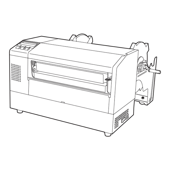
  • Seite 112: Äußeres

    1. PRODUKT ÜBERBLICK GERMAN VERSION GO1-33028 1.5 Äußeres Die hier verwendeten Bezeichnungen, finden sich in der ganzen 1.5 Äußeres Bedienungsanleitung wieder. 1.5.1 Abmessungen HINWEIS: Mit optionalem Messer beträgt die Tiefe 470 mm. 15.2 (385) 7.1 (181) 16.9 (429) 16.8 (427) Abmessungen in Inch +(mm) LCD Display Gehäusedeckel...
  • Seite 113: Bedienfeld

    1. PRODUKT ÜBERBLICK GERMAN VERSION GO1-33028 1.5 Äußeres 1.5.4 Bedienfeld LCD Display ON LINE LED (grün) ERROR LED POWER LED (rot) (grün) POWER ON LINE ERROR [PAUSE] Taste [FEED] Taste [RESTART] Taste FEED RESTART PAUSE Nähere Informationen über das Bedienfeld finden Sie in Kapitel 4.1. 1.5.5 Details Druckkopf Block Druckkopf...
  • Seite 114: Drucker Setup

    Sie in dem Gerät arbeiten (z. B. Farbbandwechsel, Materialwechsel oder Säubern des Gerätes. • Um die besten Resultate und eine lange Lebensdauer zu erzielen, sollten Sie nur TOSHIBA TEC geprüfte Materialien und Farbbänder verwenden. • Lagern Sie die Farbbänder und das Material gemäß den Spezifikationen.
  • Seite 115: Vorbereitung

    2. DRUCKER SETUP GERMAN VERSION GO1-33028 2.2 Vorbereitung 2.2 Vorbereitung Dieser Abschnitt beschreibt das Vorgehen der Bereitstellung des Druckers. Packen Sie den Drucker und das Zubehör aus dem Karton aus. HINWEIS: 2. Richten Sie sich bei der Aufstellung des Gerätes nach den Um mit dem PC zu Sicherheitshinweisen.
  • Seite 116: Zusammebau Des Zubehörs

    2. DRUCKER SETUP GERMAN VERSION GO1-33028 2.3 Zusammebau des Zubehörs 2.3 Zusammenbau des Der folgende Absatz erläutert den Zusammenbau des Materialhalters und den Anbau an den Drucker.. Zubehörs 2.3.1 Zusammenbau des Schrauben Sie die Seitenteile mit Hilfe des Flügelschrauben wie dargestellt an die Basisplatte.
  • Seite 117: Anschluß Der Kabel

    2. DRUCKER SETUP GERMAN VERSION GO1-33028 2.4 Anschluß der Kabel 2.4 Anschluß der Kabel Der folgende Absatz beschreibt, wie der Drucker an Ihren Computer angeschlossen wird, und welche weiteren Anschlußmöglichkeiten bestehen. Abhängig von der Anwendersoftware bestehen drei Möglichkeiten den Drucker mit dem PC zu verbinden: •...
  • Seite 118: Netzanschluß

    2. DRUCKER SETUP GERMAN VERSION GO1-33028 2.5 Netzanschluß 2.5 Netzanschluß Vergewissern Sie sich, daß der Netzschalter auf AUS steht. ACHTUNG! 1. Vergewissern Sie sich, daß der Netzschalter auf AUS steht (Position Netzschalter bevor das Netzkabel eingesteckt wird. 2. Benutzen Sie nur das beiliegende Netzkabel.
  • Seite 119: Ein- / Ausschalten

    2. DRUCKER SETUP GERMAN VERSION GO1-33028 2.6 Ein- / Ausschalten 2.6 Ein- / Ausschalten Es empfiehlt sich erst den Drucker und dann den PC ein bzw. auszuschalten. Betätigen Sie den Netzschalter wie gezeigt, um den Drucker 2.6.1 Einschalten des einzuschalten. Beachten Sie, daß die ( ) Seite die EIN Stellung ist. Druckers ACHTUNG! Schalten Sie den...
  • Seite 120: Papiereinlegen

    2. DRUCKER SETUP GERMAN VERSION GO1-33028 2.7 Papiereinlegen 2.7 Papiereinlegen folgende Absatz beschreibt Vorgehensweise Materialeinlegens in den Materialhalter und der Einführung in den Drucker. 2.7.1 Einlegen des Papiers in Die folgende Zeichnung veranschaulicht das Einlegen des Materials in den Rollenhalter den Rollenhalter.
  • Seite 121 2. DRUCKER SETUP GERMAN VERSION GO1-33028 2.7 Papiereinlegen Zeichnung folgenden Punkte beschreiben 2.7.1 Einlegen des Materials Vorgehensweise des Materialeinlegens. Legen Sie das Material sorgfältig in die Rollenhalterung ein, damit die automatische Zentrierung sauber arbeitet. (Fortsetzung) WARNUNG! Druck Oberfläche Abnehmbares Achten Sie auf Ihre Finger, Seitenteil damit sie nicht durch eine herunterfallende...
  • Seite 122: Einsetzen Des Rollenhalters In Die Materialhalterung

    2. DRUCKER SETUP GERMAN VERSION GO1-33028 2.7 Papiereinlegen 2.7.2 Einsetzen des Setzen Sie die Rollenhalterung - wie dargestellt - in die Nut der Rollenhalters in die Materialhalterung. Materialhalterung Messinghüllse HINWEIS: Setzen Sie die Messinghülse genau in die Nut, so daß die Materialrolle sich leicht drehen läßt.
  • Seite 123 2. DRUCKER SETUP GERMAN VERSION GO1-33028 2.7 Papiereinlegen 2.7.3 Materialeinlegen in den Öffnen Sie den Druckkopf Block durch herunterdrücken des Drucker (Fortsetzung) Verriegelungshebels Schieben Sie den Druckkopf-Block ganz nach oben – wie durch den Pfeil dargestellt. WARNUNG! • Der Druckkopf kann sehr Druckkopf heiß...
  • Seite 124: Paiereinlegen

    2. DRUCKER SETUP GERMAN VERSION GO1-33028 2.7 Paiereinlegen 2.7.3 Materialeinlegen in den 10. Setzen Sie die Rollenhalterung - wie dargestellt - in die vordere Nut. Drucker (Fortsetzung) 11. Wenn Sie sehr dickes Material verarbeiten (z.B. TAG) kann es nötig sein den Kopfandruck mit dem Kopfandruckhebel zu lösen. Kopfandruckhebel oben unten...
  • Seite 125: Sensor Positionierung

    2. DRUCKER SETUP GERMAN VERSION GO1-33028 2.8 Sensor Positionierung 2.8 Sensor Nachdem das Material wie im letzten Absatz beschrieben eingelegt wurde sollte der Sensor positioniert werden, um den Etikettenanfang Positionierung richtig zu positionieren. 1. Öffnen Sie den Druckkopf Block wie im Kapitel 2.7.3 beschrieben 2.8.1 Durchleuchtungs- und führen Sie das Material wie gezeigt unter dem Sensor hindurch.
  • Seite 126: Einlegen Des Farbbandes

    2. DRUCKER SETUP GERMAN VERSION GO1-33028 2.9 Einlegen des Farbbandes 2.9 Einlegen des Öffnen Sie den Gehäusedeckel und den Druckkopf Block wie in Kapitel 2.7.3 beschrieben. Farbbandes Nehmen Sie die volle Farbbandrolle in die linke, den leeren Farbbandkern in die rechte Hand. WARNUNG! Setzen Sie das Farbband wie dargestellt und in den unten •...
  • Seite 127: Einsetzen Der Pcmcia Karte (Option)

    2. DRUCKER SETUP GERMAN VERSION GO1-33028 2.10 Einsetzen der PCMCIA Karte (Option) 2.10 Einsetzen der Wenn die optionale PCMCIA Schnittstellenkarte des B-852 eingebaut ist, verfügt der Drucker über zwei PCMCIA Slots. Diese können für Flash PCMCIA Karte Memory Karten oder I/O Karten, wie z.B. LAN Karten genutzt werden. (Option) Der folgende Abschnitt erläutert das Einsetzen der PCMCIA Karten.
  • Seite 128: Test Druck

    2. DRUCKER SETUP GERMAN VERSION GO1-33028 2.11 Test Druck Der folgende Testdruck stellt sicher, daß der Drucker richtig arbeitet. 2.11 Test Druck Während dieses Testlaufes wird zuerst ein leeres Etikett vorgeschoben um das Etikett über den Sensor zu positionieren, dann werden fünf Etiketten mit schrägen Linien, fünf Etiketten mit Barcodes und fünf Etiketten mit verschieden großen Buchstaben gedruckt.
  • Seite 129 2. DRUCKER SETUP GERMAN VERSION GO1-33028 2.11 Test Druck Drücken Sie nochmals die [PAUSE] Taste und der Drucker gibt 2.11 Test Druck fünf Etiketten mit Barcodes aus, das Display zeigt dann folgende (Fortsetzung) Meldung: Drücken Sie nochmals die [PAUSE] Taste und der Drucker gibt HINWEIS: fünf Etiketten mit verschieden großen Buchstaben aus.
  • Seite 130 2. DRUCKER SETUP GERMAN VERSION GO1-33028 2.11 Test Druck 15. Schalten Sie zum Beenden des Testdrucks den Drucker aus und 2.11 Test Druck wieder an. Prüfen Sie, daß das Display ONLINE zeigt und die (Fortsetzung) beiden grünen LED´s ONLINE und POWER leuchten. Beispiel des Testdrucks mit schrägen Linien.
  • Seite 131: Funktionsweise

    Etiketten können auf einem Rechner mit Hilfe von allgemein erhältlichen Etikettengestaltungsprogrammen oder durch die Eingebe der direkten TEC Steuersequenzen erstellt werden. Wenn das optionale PCL5 Interface Board installiert wurde, kann der Drucke aus jedem Software Programm angesteuert werden, daß die HP PCL5 Sprache unterstützt.
  • Seite 132 3. FUNKTIONSWEISE GERMAN VERSION GO1-33028 3.2 Betriebsarten 3.2 Betriebsarten 2. Endlos (oder auch Batch) Modus - In diesem Modus wird das Etikett permanent bedruckt und vorgeschoben, bis die vorgegebene (Fortsetzung) Anzahl von Etiketten erreicht ist. Danach kann das Material wie beim Spendemodus abgenommen werden.
  • Seite 133: Online Mode

    4. ONLINE MODE GERMAN VERSION GO1-33028 4.1 Bedienfeld 4. ONLINE MODE Dieser Absatz beschreibt die Funktion und Bedienungs Tasten auf der Vorderseite des Druckers. • 4.1 Bedienfeld Diese Abbildung zeigt die Bedientasten und das Display des Druckers. LCD Display ON LINE LED (grün) POWER LED (grün) ERROR LED (rot)
  • Seite 134: Bedienung

    Im Dump Modus werden alle Zeichen, die vom PC gesendet werden 4.4 Dump Modus gedruckt. Empfangene Zeichen werden hexadezimal ausgedrückt. Dies erlaubt dem Anwender Programmbefehle zu verifizieren und am Programm Fehler zu beheben. Für detaillierte Angaben fragen Sie beim nächstgelegenen TOSHIBA TEC – Fachhändler nach. G4- 2...
  • Seite 135: Wartung

    7. Reinigen Sie die Walzen mit einem fusselfreiem Tuch, eventuell mit Reinigungsstift, um den Walzenreiniger. Druckkopf zu säubern, Grüner Griff anderenfalls könnte die Lebensdauer des Kopfes darunter leiden. HINWEIS: Bitte beziehen Sie den Druckkopf – Reiniger nur von Walze autorisierten TOSHIBA TEC Fachhändlern. Durchleutungs- und Reflexmarken- Sensor G5- 1...
  • Seite 136: Gehäuse Und Bedienfeld

    5. WARTUNG GERMAN VERSION GO1-33028 5.2 Lagerung Material/Farbband 5.1.2 Gehäuse und Wischen Sie das Gehäuse und das Bedienfeld mit einem weichen Tuch ab, verwenden Sie höchstens milde Reinigungsmittel. Bedienfeld ACHTUNG! Benutzen sie keinen scharfen Reinigungsmittel, Verdünner oder Benzin. 1. Entfernen Sie die Kunststoff-Kopf-Schraube, um die Messerabdeckung 5.1.3 Schneideeinheit abzunehmen.
  • Seite 137: Fehlerbehebung

    Papierstau im Messer. Entfernen Sie den Papierstau und drücken MESSERFEHL.**** Sie die [RESTART] Taste. Wenn das (Nur bei installiertem Messer.) Problem sich nicht durch Aus- und Ein- schalten des Druckers beheben läßt, wenden Sie sich an Ihren TOSHIBA TEC Fachhändler. G6- 1...
  • Seite 138: Mögliche Ursachen

    6. FEHLERBEHEBUNG GERMAN VERSION GO1-33028 6.2 Mögliche Ursachen 6.1 Fehlermeldungen (Fortsetzung) Fehlermeldung Ursache Lösung 1. Das Ende der Materialrolle ist 1. Legen Sie neues Material ein und PAPIERENDE **** Drücken die [RESTART] Taste. erreicht. 2. Das Material nicht richtig 2. Legen Sie das Material richtig ein und drücken die [RESTART] Taste.
  • Seite 139: Beheben Eines Paierstaus

    6. FEHLERBEHEBUNG GERMAN VERSION GO1-33028 6.3 Beheben eines Paierstaus 6.3 Beheben eines Dieser Absatz beschreibt detailliert, wie ein Papierstau behoben werden kann. Papierstaus Entfernen Sie daß gestaute Material wie folgt: ACHTUNG! Zerkratzen Sie nicht den Öffnen Sie den Gehäusedeckel. Druckkopf oder die Walzen Öffnen Sie den Druckkopf-Block.
  • Seite 140: Sensoranpassung

    6. FEHLERBEHEBUNG GERMAN VERSION GO1-33028 6.4 Sensoranpassung Der Durchleuchtungssensor mißt die Menge des Lichts, die durch das 6.4 Sensoranpassung Material geht, um den Etikettenanfang zu erkennen. Bei vorgedruckten Etiketten kann die Lichtundurchlässigkeit der (Vorbedruckungs) Tinte HINWEIS: zu Falschpositionierung führen. Wenn dies der Fall ist, gehen Sie bitte folgendermaßen vor: 1.
  • Seite 141: Anhang 1 Spezifikationen

    Der Anhang 1 beschreibt die Spezifikationen des Druckers, des Verbrauchsmaterials, des Farbbandes und der Etiketten. A1.1 Drucker Der Drucker hat folgende Spezifikationen. Model B-852-TS12-QP Item Netzspannung AC 220 – 240V, 50 Hz Leistungsaufnahmen 1.1 A, 217 W max. während des druckens 0.1 A, 20 W max.
  • Seite 142: Anahang 1 Spezifikationen

    Flash Memory Karte: 4MB Karte (siehe Seite 2-14) HINWEIS: Alle Optionen sind über die TOSHIBA TEC Fachhändler zu beziehen. A1.3 Material Verwenden Sie nur von TOSHIBA TEC zugelassene Materialien. Für andere Materialien können wir keine Garantie übernehmen. A1.3.1 Material Arten Zwei Materialarten lassen sich mit dem Drucker verarbeiten: Etiketten und Kartonmaterial.
  • Seite 143: A1.3.2 Erkennungsbereich Des Durchleutungssensors

    ANHANG 1 SPEZIFIKATIONEN GERMAN VERSION GO1-33028 A1.3 Material A1.3.1 Material Arten (Fortsetzung) [Einheit: mm] Betriebsart Endlos Modus Schneide Modus Item Etikett: 38.0 Min. Etiketten Höhe (mit Zwischenraum) 15.0 Karton: 25.4 Etikettenlänge Min. 12.5 Min. 32.0 Breite einschließlich Trägerpapier 100.0- 242.0 100.0 –...
  • Seite 144: Anhang 1 Spezifikation

    ANHANG 1 SPEZIFIKATION GERMAN VERSION GO1-33028 A1.3 Material A1.3.3 Einstellbereich des Reflexionssensors Der Reflexionssensor ist von der Mitte des Druckers bis zum linken Rand hin verstellbar. Der Reflexionsfaktor der Black Mark sollte 10% oder weniger betragen bei einer Wellenlänge von 950 nm. Der Reflexionssensor sollte mittig auf die Black Mark positioniert werden.
  • Seite 145: A1.4 Farbband

    ANHANG 1 SPEZIFIKATION GERMAN VERSION GO1-33028 A1.4 Farbband A1.4 Farbband Verwenden Sie bitte nur von TOSHIBA TEC freigegebene Farbbänder. Für andere Farbbänder können wir keine Garantie übernehmen, sie können den Druckkopf sogar beschädigen. Type Rolle Breite 120 – 220 mm empfohlene Breiten sind 120, 160 und 220 mm.
  • Seite 146: Anhang 2 Fehermeldungen Und Led

    ANHANG 2 FEHERMELDUNGEN UND LED GERMAN VERSION GO1-33028 ANHANG 2 FEHLEMELDUNGEN UND LED ANHANG 2 FEHLERMELDUNGEN UND LED Dieser Anhang beschreibt die Fehlermeldungen im Display. Symbols bei der Anzeige : LED leuchtet. : LED blinkt. : LED ist aus. 2: **** Anzahl der ungedruckten Etiketten (bis 9999 Stück) 3: %%%%%%% freier Speicher der ATA Karte (in K Bytes) 4: ### freier Speicher der Flash Memory Karte für den "PC save area"...
  • Seite 147 ANHANG 2 FEHERMELDUNGEN UND LED GERMAN VERSION GO1-33028 ANHANG 2 FEHLEMELDUNGEN UND LED HINWEISE: • Wenn ein Syntaxfehler in den Steuersequenzen entdeckt wird, so werden die ersten 16 Zeichen des falschen Befehls angezeigt.( Die Befehlsbegrenzer (ESC; LF; NULL) werden nicht dargestellt. Beispiel 1 [ESC] T20 E30 [LF] [NUL] Syntax Fehler...
  • Seite 148: Anhang 3 Kabelbelegung

    ANHANG 3 KABELBELEGUNG GERMAN VERSION GO1-33028 ANHANG 3 KABELBELEGUNG ANHANG 3 KABELBELEGUNG Datenkabel Um elektrische Störeinflüsse auszuschließen, sollte das Datenkabel folgendermaßen aussehen: • Vollkommen abgeschirmt und mit einem Metallstecker versehen. • So kurz wie möglich. • Es sollte nicht mit dem Netzkabel zusammengebunden werden. •...
  • Seite 149: Anhang 4 Druckbeispile

    ANHANG 4 DRUCKBEISPIELE GERMAN VERSION GO1-33028 ANHANG 4 DRUCKBEISPILE ANHANG 4 DRUCKBEISPIELE Druckerschriftarten GA4-1...
  • Seite 150 ANHANG 4 DRUCKBEISPIELE GERMAN VERSION GO1-33028 ANHANG 4 DRUCKBEISPILE ANHANG 4 DRUCKBEISPIELE (FORTSETZUNG) Barcodes 0: JAN8, EAN8 1: MSI 2: Interleaved 2 of 5 3: CODE39 (Standard) 4: NW7 5: JAN13, EAN13 6: UPC-E 7: EAN13+2 digits 8: EAN13+5 digits A:CODE128 B: CODE39 (Full ASCII) C: CODE93...
  • Seite 151 ANHANG 4 DRUCKBEISPIELE GERMAN VERSION GO1-33028 ANHANG 4 DRUCKBEISPILE ANHANG 4 DRUCKBEISPIELE (FORTSETZUNG) K: UPC-A L: UPC-A+2 digits M: UPC-A+5 digits N: UCC/EAN128 O: Industrial 2 of 5 P: PDF417 Q: Data Matrix R: Customer bar code S: Customer bar code of high priority T: QR code U: POSTNET V: RM4SCC...
  • Seite 152 GLOSSARE GERMAN VERSION GO1-33028 GLOSSARE GLOSSARE Auflösung Etikett Die Anzahl der Details, in die die Abbildung Aufkleber; Material mit selbstklebender Unterseite. aufgeteilt werden kann. Die kleinste Einheit wird Pixel genannt. Wird die Auflösung größer so steigt Fed gap Sensor die Anzahl der kleinsten Elemente, was zu einer Siehe Durchleuchtungssensor.
  • Seite 153 GLOSSARE GERMAN VERSION GO1-33028 GLOSSARE PCMCIA Schnittstelle Verbrauchsmaterial Diese optionale Schnittstelle ermöglicht es die Etikettenmaterial und Farbbänder. Kreditkarten großen PC Karten in dem Drucker zu installieren, z.B. Flash Memory Karte, LAN Karte. Vorgedrucktes Material PCMCIA ist die Abkürzung für "Personal Ein Material, bei dem schon Logos oder andere Computer Memory...
  • Seite 154 INDEX GERMAN VERSION GO1-33028 INDEX INDEX Abmessungen GA1-1 Kabelbelegung GA1-1 Ausgabemodus GA1-1 KB-80-QM Tastatur 2-4 Auflösung GA1-1 Kopf Block Verriegelungshebel 1-4, 2-10 Kopfandruckhebel 1-3, 2-11 Barcode GA1-1 Batch Modus 3-2 LCD Anzeige 1-3, 1-4, 4-1, GA1-1, GA2-1 Bedienfeld 1-3, 4-1 Leistungsaufnahme GA1-1 Black Mark GA1-2 Black Mark Länge GA1-3...
  • Seite 155 INDEX GERMAN VERSION GO1-33028 INDEX Schneide Modus 3-2 Sensoreinstellungen 6-4 Spende-Modus 3-1 Start Stopp Schnittstelle 1-3, 2-4 Start Stopp Schnittstellenkarte GA1-2 Sensor 2-12, 5-1 Sensor Justagerad 2-12 Serielle Schnittstelle 1-3 Tag GA1-2 Tastatur GA1-2 Tastatur Schnittstelle 1-3 Test Druck 2-15 Thermal Direkt GA1-1 Thermal Transfer GA1-1 Trägerpapier GA1-3...
  • Seite 156 Impresora Térmica TEC B-852-TS12-QP Manual de instrucciones...
  • Seite 157 No intente efectuar reparaciones o modificaciones en este equipo. Si ocurriese un fallo que no se puede rectificar utilizando este manual, apague la máquina, desconecte la alimentación y contacte con su Distribuidor Autorizado TOSHIBA TEC para la asistencia técnica. Significado de cada símbolo Este símbolo indica puntos de advertencia (incluyendo precauciones).
  • Seite 158 Compromiso de Mantenimiento Utilice nuestros servicios de mantenimiento. Después de comprar la impresora, contacte con su Distribuidor Autorizado TOSHIBA TEC al menos una vez al año para su mantenimiento y limpieza. En caso contrario, se puede almacenar suciedad en la impresora y causar un incendio o mal funcionamiento.
  • Seite 159 SPANISH VERSION SO1-33028 INDICE Page VISTA GENERAL ........................ S1-1 Introducción......................... S1-1 Características ......................S1-1 Desembalaje ....................... S1-1 Accesorios........................S1-2 Vista General....................... S1-3 1.5.1 Dimensiones......................... S1-3 1.5.2 Vista Frontal ......................... S1-3 1.5.3 Vistal Posterior ......................S1-3 1.5.4 Panel de Operaciones....................S1-4 1.5.5 Interior ..........................
  • Seite 160: Indice

    ATENCION! 1. Este manual no puede ser copiado total o parcialmente sin permiso escrito de TOSHIBA TEC. 2. El contenido de este manual puede ser cambiado sin previo aviso. 3. Para cualquier consulta sobre este manual diríjase a su distribuidor autorizado TOSHIBA TEC.
  • Seite 161: Vista General

    1. VISTA GENERAL 1.1 Introducción Gracias por elegir la impresora térmica de la serie B-852 de TOSHIBA TEC. Este manual contiene desde información sobre la configuración general hasta cómo confirmar el funcionamiento de la impresora utilizando un test de impresión, por lo que rogamos sea leído atentamente para obtener el máximo rendimiento de su impresora.
  • Seite 162: Accesorios

    Cable de alimentación PRECAUCIÓN! (P/No. H00436904 A) (Doc./No. EO1-33028) Asegúrese de utilizar un lápiz limpiador aprobado TEC Label/Tag Printer por TOSHIBA TEC. De no B-850-TS12-QP Owner's Manual ser así se puede acortar la Mode d'emploi Bedienungsanleitung Manual de instrucciones Gebruikershandleiding vida del cabezal.
  • Seite 163: Vista General

    1. VISTA GENERAL SPANISH VERSION SO1-33028 1.5 Vista General Los nombres de las partes o unidades descritas en esta sección se utilizan 1.5 Vista General en los capítulos posteriores. 1.5.1 Dimensiones NOTA: Cuando el módulo cortador opcional está instalado la 15.2 (385) 7.1 (181) profundidad es de 470 mm (18.5...
  • Seite 164: Panel De Operaciones

    1. VISTA GENERAL SPANISH VERSION SO1-33028 1.5 Vista General 1.5.4 Panel de Operaciones Pantalla LCD INDICADOR DE “ON LINE” (Verde) INDICADOR DE ENCENDIDO INDICADOR (Verde) DE ERROR POWER ON LINE ERROR (Rojo) Tecla de [FEED] Tecla de [PAUSE] Tecla de [RESTART] FEED RESTART PAUSE...
  • Seite 165: Instalación De La Impresora

    Tenga precaución cuando limpie el cabezal de impresión, puesto que durante la impresión se calienta bastante. Espere hasta que se enfríe antes de limpiarlo. Utilice exclusivamente, limpiadores de cabezal recomendados por TOSHIBA TEC. • No apague la impresora o desconecte el cable de alimentación mientras la impresora está...
  • Seite 166: Antes De Empezar

    Manual de Programación de la impresora. La impresora también se puede controlar con sus propios comandos de programación. Por favor, póngase en contacto con su distribuidor autorizado TOSHIBA TEC para el Manual de Programación. S2- 2...
  • Seite 167: Instalación De Los Accesorios

    2. INSTALACIÓN DE LA IMPRESORA SPANISH VERSION SO1-33028 2.3 Instalación de los Accesorios 2.3 Instalación de los El siguiente procedimiento detalla los pasos necesarios para el montaje del Bloque de Soporte de Papel y su sujeción a la impresora B-852 para Accesorios la posterior colocación del papel.
  • Seite 168: Conexión De Los Cables A La Impresora

    2. INSTALACIÓN DE LA IMPRESORA SPANISH VERSION SO1-33028 2.4 Conexión de los Cables a la Impresora 2.4 Conexión de los A continuación se detalla cómo conectar los cables de la impresora B-852 al ordenador, y cómo conectar los cables de otros dispositivos tales como Cables a la el teclado KB-80-QM, etc.
  • Seite 169: Conexión Del Cable De Alimentación

    2. INSTALACIÓN DE LA IMPRESORA SPANISH VERSION SO1-33028 2.5 Conexión del Cable de Alimentación 1. Asegúrese de que el interruptor de la impresora está en la posición 2.5 Conexión del Cable OFF. de Alimentación PRECAUCIÓN! 1. Asegúrese que el interruptor de la impresora está...
  • Seite 170: Encendido/Apagado De La Impresora

    2. INSTALACIÓN DE LA IMPRESORA SPANISH VERSION SO1-33028 2.6 Encendido/Apagado de la Impresora 2.6 Encendido/Apagado Cuando la impresora está conectada al ordenador, es una buena práctica de la Impresora el encender la impresora antes que el ordenador, y apagar el ordenador antes que la impresora.
  • Seite 171: Colocación Del Papel

    2. INSTALACIÓN DE LA IMPRESORA SPANISH VERSION SO1-33028 2.7 Colocación del Papel El siguiente procedimiento muestra los pasos necesarios para instalar el 2.7 Colocación del Papel papel en la Unidad de Soporte de Papel, y ajustar su posición en el Bloque de Soporte de Papel de la parte trasera de la impresora B-852.
  • Seite 172 2. INSTALACIÓN DE LA IMPRESORA SPANISH VERSION SO1-33028 2.7 Colocación del Papel La figura inferior y los pasos que se detallan, describen el procedimiento 2.7.1 Colocación del Papel de la colocación del papel en el Eje de Papel y su montaje en la Unidad en la Unidad de Soporte de Soporte de Papel.
  • Seite 173: Colocación De La Unidad De Soporte Del Papel En El Bloque De Soporte De Papel

    2. INSTALACIÓN DE LA IMPRESORA SPANISH VERSION SO1-33028 2.7 Colocación del Papel Coloque la Unidad de Soporte de Papel ensamblado, en las muescas 2.7.2 Colocación de la del Bloque de Soporte de Papel, como muestra la figura inferior. Unidad de Soporte del Papel en el Bloque de Casquillos de Latón Soporte de Papel...
  • Seite 174 2. INSTALACIÓN DE LA IMPRESORA SPANISH VERSION SO1-33028 2.7 Colocación del Papel 2.7.3 Colocación del papel Libere el Bloque del Cabezal de Impresión, presionando hacia abajo la Palanca de Liberación del Bloque del Cabezal , tal y como se en la impresora (cont.) muestra.
  • Seite 175 2. INSTALACIÓN DE LA IMPRESORA SPANISH VERSION SO1-33028 2.7 Colocación del Papel 2.7.3 Colocación del Papel 10. Después de la colocación del papel, no olvide mover la Unidad de Suporte de Papel a la muesca delantera del Bloque de Soporte de en la Impresora (cont.) Papel, como se muestra abajo.
  • Seite 176: Ajuste De La Posición Del Sensor

    2. INSTALACIÓN DE LA IMPRESORA SPANISH VERSION SO1-33028 2.8 Ajuste de la Posición de los Sensores 2.8 Ajuste de la Posición Después de la colocación del papel, indicado anteriormente, normalmente es necesario ajustar los Sensores de Papel utilizados para detectar el de los Sensores comienzo de la posición de impresión de la etiqueta o cartulina.
  • Seite 177: Colocación De La Cinta

    2. INSTALACIÓN DE LA IMPRESORA SPANISH VERSION SO1-33028 2.9 Colocación de la Cinta 1. Levante La Cubierta Superior, libere y levante el bloque del Cabezal 2.9 Colocación de la de Impresión, como se describe en la Sección 2.7.3, pasos 1 y 2. Cinta 2.
  • Seite 178: Colocación De Las Tarjetas Pcmcia Opcionales

    2. INSTALACIÓN DE LA IMPRESORA SPANISH VERSION SO1-33028 2.10 Colocación de las Tarjetas PCMCIA Opcionales 2.10 Colocación de las Al instalar el interface PCMCIA opcional en la impresora B-852, existirán dos ranuras PCMCIA disponibles, tal y como muestra la figura Tarjetas PCMCIA inferior.
  • Seite 179: Prueba De Impresión

    2. INSTALACIÓN DE LA IMPRESORA SPANISH VERSION SO1-33028 2.11 Prueba de Impresión 2.11 Prueba de Impresión El siguiente procedimiento de prueba, le permite realizar una prueba de impresión para verificar impresora está funcionando correctamente. Durante la ejecución de la prueba, la impresora primero avanza una etiqueta en blanco para que el sensor detecte o la Marca Negra o la Separación entre etiquetas, y entonces imprimirá...
  • Seite 180 2. INSTALACIÓN DE LA IMPRESORA SPANISH VERSION SO1-33028 2.11 Prueba de Impresión Pulse la tecla [PAUSE] de nuevo y ahora la impresora imprimirá 2.11 Prueba de cinco etiquetas con ejemplos de códigos de barras y la Pantalla LCD Impresión (cont.) de Mensajes mostrará...
  • Seite 181 2. INSTALACIÓN DE LA IMPRESORA SPANISH VERSION SO1-33028 2.11 Prueba de Impresión 2.11 Prueba de Impresión 15. Si se ha terminado de realizar la prueba de impresión, apague la impresora, vuelva a encenderla y verifique que la Pantalla LCD de (cont.) Mensajes muestra ON LINE y que las luces de ON LINE y POWER están encendidas.
  • Seite 182: Operativa De La Impresora

    Las etiquetas se crearán en el ordenador conectado a la impresora, utilizando bien un programa generador de etiquetas comercial o el lenguaje de comandos de programación TEC. O si se ha instalado la NOTAS: placa de interfaz PCL5, la impresora será capaz de imprimir desde 1.
  • Seite 183 3. OPERATIVA DE LA IMPRESORA SPANISH VERSION SO1-33028 3.2 Modos de Operación Modos de Operación 2. Modo continuo – En este modo, el número de etiquetas especificadas en el comando de emisión se imprime de forma (cont.) continua. Después de imprimir la última etiqueta de la serie las etiquetas se pueden cortar del rollo de etiquetas como se describe en el modo anterior.
  • Seite 184: Modo On Line

    4. MODO ON LINE SPANISH VERSION SO1-33028 4.1 Panel de Operaciones 4. MODO ON LINE Este capítulo describe el uso y el propósito de las teclas del Panel de Operaciones en Modo Online. Cuando la impresora está en Modo Online y conectada a un ordenador, se puede lograr la impresión de imágenes sobre etiquetas o tickets.
  • Seite 185: Reset

    En modo Volcado, se imprimirá cualquier carácter enviado por el 4.4 Modo Volcado ordenador. Los caracteres recibidos, se expresan en valor hexadecimal. Esto permite verificar los comandos de programación y depurar el programa. Para más detalles, refiérase a su Distribuidor TOSHIBA TEC Autorizado. S4- 2...
  • Seite 186: Mantenimiento

    Pestaña para con la impresora o puede levantar el sensor acortar la vida del cabezal. NOTA: Rodillo de impresión Por favor, adquiera el limpiador de Cabezal en su Sensores transmisivo distribuidor autorizado y reflectivo TOSHIBA TEC. S5- 1...
  • Seite 187: Cubiertas Y Paneles

    5. MANTENIMIENTO SPANISH VERSION SO1-33028 5.2 Cuidado/Manejo del Papel y la Cinta Limpie la cubierta y el panel frontal con un paño suave seco. Limpie la 5.1.2 Cubiertas y Paneles suciedad con un paño ligeramente humedecido con agua. PRECAUCIÓN! No utilice disolventes incluidos aguarrás y bencina, ya que puede decolorar la cubierta.
  • Seite 188: Solución De Errores

    ATENCIÓN! Si su problema no se encuentra entre los expuestos en este capítulo, no intente reparar la impresora. Apague, desenchufe la impresora y contacte con su distribuidor autorizado TOSHIBA TEC para solicitar asistencia. 6.1 Mensajes de Error NOTAS: • Si un error no se elimina pulsando la tecla [RESTART], apague y encienda la impresora.
  • Seite 189: Posibles Problemas

    Apague y encienda la impresora. Si esto no soluciona el problema, apague la impresora y llame a su distribuidor autorizado TOSHIBA TEC. 6.2 Posibles Problemas Esta sección describe problemas que se pueden dar al utilizar la impresora, y sus posibles causas y soluciones.
  • Seite 190: Cómo Quitar El Papel Atascado

    Cortador, contacte resíduos de adhesivo de las etiquetas en las cuchillas del cortador. con su distribuidor autorizado No utilice papel fuera de especificaciones con el cortador. Si tiene TOSHIBA TEC. atascos de papel frecuentemente, contacte con su distribuidor autorizado. S6- 3...
  • Seite 191: Configuración Del Umbral De Etiqueta Preimpresa

    6. SOLUCIÓN DE ERRORES SPANISH VERSION SO1-33028 6.4 Configuración de Umbral de Etiqueta Preimpresa Para mantener la posición de impresión constante la impresora utiliza el 6.4 Configuración del sensor transmisivo para detectar el espacio entre etiquetas midiendo la Umbral de cantidad de luz que pasa a través del papel.
  • Seite 192: Apendice 1 Especificaciones

    APENDICE 1 ESPECIFICACIONES El apéndice 1 describe las especificaciones de la impresora y accesorios de la impresora B-852. A1.1 Impresora A continuación se muestran las especificaciones de la impresora. Modelo B-852-TS12-QP Característica Tensión de alimentación AC220 – 240V, 50 Hz Consumo Máximo 1.1 A, 217 W ( parada: 0.1 A, 20 W )
  • Seite 193: A1.2 Opciones

    Disponible en su distribuidor autorizado TOSHIBA TEC más cercano. A1.3 Papel Asegúrese de que el papel que utilice esté aprobado por TOSHIBA TEC. La garantía no se aplica si sucediera un problema producido por utilizar papel no aprobado por TOSHIBA TEC.
  • Seite 194: A1.3.2 Área De Detección Del Sensor Transmisivo

    NOTAS: 1. Para asegurarse la calidad de impresión y la vida del cabezal de impresión utilice sólo papel recomendado por TOSHIBA TEC. 2. Al utilizar corte en la emisión asegúrese de que la longitud de la etiqueta más el espacio entre etiquetas supere los 38 mm.
  • Seite 195: A1.3.3 Área De Detección Del Sensor Reflectivo

    APENDICE 1 ESPECIFICACIONES SPANISH VERSION SO1-33028 A1.3 Papel A1.3.3 Área de Detección del Sensor Reflectivo El sensor reflectivo es móvil desde el centro hasta el borde izquierdo del papel. El factor de reflexión de la marca negra debe ser de un 10% o menor, con una longitud de onda de 950 nm. El sensor reflectivo debe estar alineado con el centro de la marca negra.
  • Seite 196: A1.4 Cinta

    A1.4 Cinta A1.4 Cinta Por favor, asegúrese de que la cinta que está utilizando esté aprobada por TOSHIBA TEC. No se aplica la garantía por un problema provocado por la utilización de cintas no aprobadas. Para más información respecto a cintas aprobadas por TOSHIBA TEC, por favor, contacte con su distribuidor.
  • Seite 197: Apendice 2 Mensajes Y Señales Luminosas

    APENDICE 2 MENSAJES Y SEÑALES LUMINOSAS SPANISH VERSION SO1-33028 APENDICE 2 MENSAJES Y SEÑALES LUMINOSAS APENDICE 2 MENSAJES Y SEÑALES LUMINOSAS El apéndice 4 describe los mensajes en la pantalla del panel de operaciones. Símbolos en el mensaje : Indicador iluminado. : Indicador parpadeando.
  • Seite 198 APENDICE 2 MENSAJES Y SEÑALES LUMINOSAS SPANISH VERSION SO1-33028 APENDICE 2 MENSAJES Y SEÑALES LUMINOSAS NOTAS: • Si se encuentra un error de comando en el comando recibido, se visualizan los primeros 16 caracteres del comando erróneo. (Sin embargo, [LF] y [NUL] no se visualizarán.) Ejemplo 1 [ESC] T20 E30 [LF] [NUL] Error de comando...
  • Seite 199: Apendice 3 Interfaz

    APENDICE 3 INTERFAZ SPANISH VERSION SO1-33028 APENDICE 3 INTERFAZ APENDICE 3 INTERFAZ Cables de conexión Para evitar radiaciones e interferencias de ruido eléctrico, los cables de conexión deben reunir los siguientes requisitos: • Totalmente aislados con metal o conectores metalizados. •...
  • Seite 200: Apendice 4 Ejemplos De Impresión

    APENDICE 4 EJEMPLOS DE IMPRESIÓN SPANISH VERSION SO1-33028 APENDICE 4 EJEMPLOS DE IMPRESIÓN APENDICE 4 EJEMPLOS DE IMPRESIÓN Fuentes de letras SA4-1...
  • Seite 201 APENDICE 4 EJEMPLOS DE IMPRESIÓN SPANISH VERSION SO1-33028 APENDICE 4 EJEMPLOS DE IMPRESIÓN APENDICE 4 EJEMPLOS DE IMPRESIÓN (Cont.) Fuentes de letras 0: JAN8, EAN8 1: MSI 2: Interleaved 2 of 5 3: CODE39 (Standard) 4: NW7 5: JAN13, EAN13 6: UPC-E 7: EAN13+2 digits 8: EAN13+5 digits...
  • Seite 202 APENDICE 4 EJEMPLOS DE IMPRESIÓN SPANISH VERSION SO1-33028 APENDICE 4 EJEMPLOS DE IMPRESIÓN APENDICE 4 EJEMPLOS DE IMPRESIÓN (Cont.) K: UPC-A L: UPC-A+2 digits M: UPC-A+5 digits N: UCC/EAN128 O: Industrial 2 of 5 P: PDF417 Q: Data Matrix R: Customer bar code S: Customer bar code of high priority T: QR code U: POSTNET...
  • Seite 203: Glosarios

    GLOSARIO SPANISH VERSION SO1-33028 GLOSARIO GLOSARIO Ajuste del umbral de etiquetas Impresión por transferencia térmica Operación de ajuste del sensor para mantener en la Método de impresión en el que el cabezal térmico impresora una posición constante de impresión de impresión calienta una tinta o resina que recubre sobre papel preimpreso.
  • Seite 204 GLOSARIO SPANISH VERSION SO1-33028 GLOSARIO Modo corte Sensor de espacio entre etiquetas Modo de operación de la impresora donde se Sensor transmisivo que detecta la diferencia de instala un módulo cortador opcional para cortar el potencial entre la separación entre etiquetas y la papel automáticamente después de ser impreso.
  • Seite 205 INDICE SPANISH VERSION SO1-33028 INDICE INDICE Ajuste del umbral 6-4 Lápiz limpiador 1-2, 5-1 Altura de etiqueta + separación SA1-3 Longitud de etiqueta SA1-3 Ancho SA1-1 Longitud de impresión SA1-3 Ancho de cinta SA1-5 Longitud de la marca negra SA1-3 Ancho efectivo de impresión SA1-3 Longitud entre etiquetas SA1-3 Área de impresión garantizada SA1-4...
  • Seite 206 INDICE SPANISH VERSION SO1-33028 INDICE Tarjeta de memoria flash 2-14 Tarjeta PCMCIA 2-14 Tecla FEED 1-4, 4-1 Tecla PAUSE 1-4, 4-1 Tecla RESTART 1-4, 4-1 Tensión de alimentación SA1-1 Térmico directo SA1-1 Test print 2-15 Transferencia térmica SA1-1 Unidad de soporte de papel 1-2, 1-3, 2-7 Unidad de teclado KB-80-QM 2-4 Velocidad de impresión SA1-1...
  • Seite 207 TEC Thermische Drukker B-852-TS12-QP Gebruikershandleiding...
  • Seite 208: Betekenis Van De Symbolen

    Herstel of wijzig deze uitrusting niet zelf. Indien een fout zich voordoet dat niet kan verholpen worden met behulp van de werkwijzen die in deze handleiding beschreven worden, zet dan het toestel af, haal de stekker uit het stopcontact en stel u in verbinding met een erkende TOSHIBA TEC verdeler voor bijstand. Betekenis van de symbolen Dit symbool geeft aan dat het een waarschuwing betreft.
  • Seite 209 Raadgeving betreffende het onderhoud Maak gebruik van onze onderhoudsdiensten. Doe minstens éénmaal per jaar beroep op een TOSHIBA TEC verantwoordelijke om de binnenzijde van het toestel te laten reinigen. Een overdadige ophoping van stof in het toestel kan aanleiding geven tot brand of een verkeerde werking van het toestel.
  • Seite 210 DUTCH VERSION NO1-33028 INHOUDSTAFEL Page PRODUCT OVERZICHT ...................... N1-1 Inleiding........................N1-1 Eigenschappen......................N1-1 Uitpakken ........................N1-1 Toebehoren ......................... N1-2 Uitzicht ........................N1-3 1.5.1 Afmetingen ........................N1-3 1.5.2 Voorzijde ........................N1-3 1.5.3 Achterzijde........................N1-3 1.5.4 Bedieningsbord ......................N1-4 1.5.5 Binnenzijde........................N1-4 INSTELLING VAN DE PRINTER ..................
  • Seite 211 VERWITTIGING! 1. Het is verboden deze handleiding, geheel of gedeeltelijk te kopieren zonder voorafgaande schriftelijke toelating van TOSHIBA TEC. 2. De inhoud van deze handleiding kan gewijzigd worden zonder verwittiging. 3. Stel u in verbinding met uw locale erkende verdeler indien u vragen heeft over deze handleiding..
  • Seite 212: Product Overzicht

    1. PRODUCT OVERZICHT 1.1 Inleiding Wij danken u voor uw keuze van een TOSHIBA TEC etiketten/kaartjes printer van de reeks B-852. In deze gebruikershandleiding vindt u een beschrijving van de algemene instelling van de printer en tevens hoe u de werking van de printer kunt controleren door middel van een printtest.
  • Seite 213: Toebehoren

    Gebruikershandleiding (1exemplaar) Voedingsnoer (1 stuk) VERWITTIGING! (P/No. H00436904 A) (Doc./No. EO1-33028) Gebruik steeds een drukkopreiniger die door TEC Label/Tag Printer TOSHIBA TEC erkend is, B-850-TS12-QP Owner's Manual zoniet kan dit aanleiding Mode d'emploi Bedienungsanleitung Manual de instrucciones Gebruikershandleiding geven tot een kortere...
  • Seite 214: Uitzicht

    1. PRODUCT OVERZICHT DUTCH VERSION NO1-33028 1.5 Uitzicht De onderdelen of wisselstukken die vernoemd worden in dit deel, worden 1.5 Uitzicht in de volgende hoofdstukken opnieuw aangehaald. 1.5.1 Afmetingen OPMERKING: Wanneer de snijdmodule (optie) werd, is de diepte 470mm (18.5 inches).
  • Seite 215: Bedieningsbord

    1. PRODUCT OVERZICHT DUTCH VERSION NO1-33028 1.5 Uitzicht 1.5.4 Bedieningsbord Berichtenscherm (LCD) ON LINE VERKLIKKER (Groen) ERROR VERKLIKKER POWER VERKLIKKER (Rood) (Green) POWER ON LINE ERROR [PAUSE] toets [FEED] toets [RESTART] toets FEED RESTART PAUSE Zie deel 4.1 voor bijkomende informatie over het bedieningsbord. Drukkopeenheid Drukkop 1.5.5 Binnenzijde...
  • Seite 216: Instelling Van De Printer

    Wees voorzichtig bij de reiniging van de thermische drukkop, deze kan bijzonder heet worden tijdens het printen. Wacht enige tijd tot de drukkop voldoende afgekoeld is. Gebruik enkel de drukkopreiniger die aanbevolen wordt door TOSHIBA TEC voor de reiniging van de drukkop. •...
  • Seite 217: Werkwijze Voor Gebruik

    B-852 printer laat u toe drivers te gebruiken die PCL5 ondersteunen. De printer kan ook gecontroleerd worden d.m.v. zijn eigen printcommando's. Stel u in verbinding met uw Toshiba TEC verdeler voor de Interface/ Communicatie handleiding. N2-2...
  • Seite 218: Montage Van Het Toebehoren

    2. INSTELLING VAN DE DRUKKER DUTCH VERSION NO1-33028 2.3 Montage van het toebehoren Montage van het Volgende werkwijze duidt aan hoe u de mediahouder en zijn drager kunt monteren en op de printer bevestigen zodat media kan geladen worden. toebehoren Bevestig de linker (L) en de rechter (R) staander door middel van 2.3.1 Montage van de de twee M-4X6 vleugelvijzen op de basisplaat van de drager zoals...
  • Seite 219: Aansluiting Van De Kabels Met De Printer

    2. INSTELLING VAN DE DRUKKER DUTCH VERSION NO1-33028 2.4 Aansluiting van de kabels met de printer 2.4 Aansluiting van In de volgende paragrafen vindt u een beschrijving van de aansluiting van de kabels van de B-852 printer met de host computer of andere toestellen, de kabels met de zoals een KB-80-QM toetsenbord, enz.
  • Seite 220: Aansluiting Van Het Voedingsnoer

    2. INSTELLING VAN DE DRUKKER DUTCH VERSION NO1-33028 2.5 Aansluiting voedingsnoer Aansluiting van het 1. Vergewis u ervan dat de spanningschakelaar wel degelijk op de voedingsnoer positie Uit staat. VERWITTIGING! 1. Wees zeker dat de spanningschakelaar op de positie Uit staat Spanningschakelaar voor u het...
  • Seite 221: Het Aan En Afzetten Van De Drukker

    2. INSTELLING VAN DE DRUKKER DUTCH VERSION NO1-33028 2.6 Het aan en afzetten van de drukker Het aan en afzetten Wanneer de drukker met de host computer is aangesloten, is het een van de drukker goede gewoonte om eerst de drukker onder spanning te zetten en pas dan de host computer en eerst de host computer af te zetten en daarna de drukker.
  • Seite 222: Het Laden Van Media

    2. INSTELLING VAN DE PRINTER DUTCH VERSION NO1-33028 2.7 Het laden van media Het laden van In onderstaande werkwijze leest u de verschillende stappen die nodig zijn voor de installatie van de media op de mediahouder en de regeling van media zijn positie op de mediadrager aan de achterzijde van de printer.
  • Seite 223 2. INSTELLING VAN DE PRINTER DUTCH VERSION NO1-33028 2.7 Het laden van media 2.7.1 Het laden van media De volgende stappen en onderstaande figuur beschrijven hoe u de media op de mediahouder kunt plaatsen op de voedingsas en hoe u de mediahouder opnieuw kunt (vervolg) monteren.
  • Seite 224: Installatie Van De Mediahouder Op De Mediadrager

    2. INSTELLING VAN DE PRINTER DUTCH VERSION NO1-33028 2.7 Het laden van media Plaats de gemonteerde mediahouder op de achterste inkepingen van 2.7.2 Installatie van de de drager volgens onderstaande figuur. mediahouder op de Koperen afsluiting mediadrager OPMERKING: Zorg ervoor dat de koperen Achterste inkeping afsluitingen op de inkepingen passen zodat de mediahouder...
  • Seite 225 2. INSTELLING VAN DE PRINTER DUTCH VERSION NO1-33028 2.7 Het laden van media 2.7.3 Het laden van media in Duw de drukkophendel naar beneden om de drukkopeenheid te de printer (vervolg) verlossen zoals hieronder aangeduid. Hef de drukkopeenheid zover mogelijk op in de richting van de pijl VERWITTIGING! in onderstaande figuur.
  • Seite 226 2. INSTELLING VAN DE DRUKKER DUTCH VERSION NO1-33028 2.7 Het laden van media 10. Nadat u de media geladen heeft, moet u de mediahouder verplaatsen 2.7.3 Het laden van media in naar de voorste inkepingen van de mediadrager zoals hieronder de printer (vervolg) aangeduid.
  • Seite 227: Regeling Van De Sensors

    2. INSTELLING VAN DE DRUKKER DUTCH VERSION NO1-33028 2.8 Regeling van de sensors Na het laden van de media zoals beschreven in voorgaande paragrafen, Regeling van de moeten de media sensoren die de begin- en eindpositie van het printen op sensors een etiket of kaartje detecteren doorgaans geregeld worden.
  • Seite 228: Het Laden Van Lint

    2. INSTELLING VAN DE PRINTER DUTCH VERSION NO1-33028 2.9 Het laden van lint Het laden van lint Hef de bovenkap en verlos de drukkopeenheid zoals beschreven in deel 2.7.3, stappen 1 en 2. Hou de lint voedingsrol in uw linker hand en de opvangrol in uw VERWITTIGING! rechter hand.
  • Seite 229: Installatie Van Pcmcia Optie Kaarten

    2. INSTELLING VAN DE PRINTER DUTCH VERSION NO1-33028 2.10 Installatie van PCMCIA optie kaarten 2.10 Installatie van Wanneer de PCMCIA interface kaart in optie geïnstalleerd wordt op een B-852 printer, zijn twee PCMCIA slots beschikbaar (zie onderstaande PCMCIA optie figuur). Het is dus mogelijk een Flash geheugen kaart of een I/O kaart kaarten zoals LAN kaarten te installeren.
  • Seite 230: Printtest

    2. INSTELLING VAN DE PRINTER DUTCH VERSION NO1-33028 2.11 Printtest Met de volgende procedure kunt u een printtest uitvoeren om de correcte 2.11 Printtest werking van de printer na te gaan. Tijdens deze test, voert de printer eerst een blanco etiket uit om de sensoren de kans te bieden de zwarte stip of de opening tussen de etiketten te detecteren.
  • Seite 231 2. INSTELLING VAN DE PRINTER DUTCH VERSION NO1-33028 2.11 Printtest 2.11 Printtest (vervolg) Druk opnieuw op de [PAUSE] toets en de printer voert nu 5 etiketten uit met proefbarcodes, terwijl onderstaand bericht blijft verschijnen op het LCD scherm. OPMERKING: Indien een fout zich voordoet tijdens de printtest, verschijnt Druk opnieuw op de [PAUSE] toets en de printer voert nu 5 een foutmelding op het scherm...
  • Seite 232 2. INSTELLING VAN DE PRINTER DUTCH VERSION NO1-33028 2.11 Printtest 2.11 Printtest (vervolg) 15. Wanneer printtest procedure afgelopen zet u de spanningschakelaar op OFF en dan weer op ON. Controleer of het bericht dat verschijnt op het LCD scherm overeenstemt met ON LINE en dat de ON LINE en POWER verklikkers oplichten.
  • Seite 233: Werking Van De Printer

    Etiketten worden aangemaakt op de Host Computer die aangesloten is 3.1 Overzicht met uw printer. Hiervoor gebruikt u een software voor het ontwerpen van etiketten die in de handel beschikbaar is of de TEC besturin- OPMERKINGEN: gsprogrammeertaal. Of, indien de PCL5 Interface kaart in optie geïnstalleerd werd, is de printer in staat te printen met behulp van gelijk...
  • Seite 234: Werkingsmodes

    3. WERKING VAN DE PRINTER DUTCH VERSION NO1-33028 3.2 Werkingsmodes 2. Doorlopende (of sequentiële) – In deze mode worden de etiketten Werkingsmodes doorlopend gedrukt en uitgevoerd tot hun aantal overeenstemt met (vervolg) het aantal dat opgegeven werd in het etiketten uitvoercommando. Wanneer het laatste etiket van de reeks gedrukt werd, kunnen de etiketten die gedrukt werden afgescheurd worden van de voedingsrol op een gelijkaardig manier als in de afpelmode.
  • Seite 235: In Lijn Mode

    4. IN LIJN MODE DUTCH VERSION NO1-33028 4.1 Bedieningsbord 4. IN LIJN MODE Dit hoofdstuk geeft een beschrijving van de in lijn mode en van de functie van de toetsen die zich bevinden op het bedieningsbord. Wanneer de printer zich in de in lijn mode bevindt en hij aangesloten is met een computer, zijn normale printoperaties zoals het printen van afbeeldingen op etiketten of gemarkeerd papier mogelijk.
  • Seite 236: Werkwijze

    In de dump mode, worden alle karakters, gestuurd door de computer afgeprint. De ontvangen data wordt afgedrukt in hexadecimale cijfers. Dit laat de gebruiker toe, eenvoudig programma’s te debuggen. Stel u in verbinding met uw TEC verdeler voor meer informatie. N4- 2...
  • Seite 237: Onderhoud

    • Gebruik enkel de Sensorstaafje bijgeleverde drukkopreiniger. Andere reinigers kunnen de levensduur van de drukkop verkorten. Drukrol OPMERKINGEN: Drukkopreinigers kunnen Voedingsholte sensor aangekocht worden bij en zwarte stip sensor TOSHIBA TEC verdelers N5- 1...
  • Seite 238: Kappen En Vlakken

    , 2H O) bevatten. niet beschadigd worden, zo beschadigd u de printer ook Stel u in verbinding met uw TEC verdeler of de fabrikant van uw media niet. Lees de richtlijnen in of linten voor meer informatie. dit hoofdstuk aandachtig.
  • Seite 239: Het Oplossen Van Fouten

    Tracht de printer niet zelf te herstellen indien een fout zich heeft voorgedaan die u niet kunt verhelpen aan de hand van dit hoofdstuk. Zet de printer af, ontkoppel het voedingsnoer en vraag bijstand aan uw Toshiba TEC verdeler. Foutmeldingen OPMERKINGEN: •...
  • Seite 240: Mogelijke Problemen

    Zet de printer af en wacht even (ongeveer 3 minuten). Indien het probleem hiermee niet opgelost is, zet u de printer af en stelt u zich in verbinding met uw Toshiba TEC verdeler. Er is een probleem met de drukkop.
  • Seite 241: Verwijdering Van Vastgelopen Media

    Sensor 4. Reinig de drukrol en de sensors zoals beschreven in deel 5.1.1. OPMERKING: Contacteer uw Toshiba TEC 5. Het vastlopen van media in het snijdmechanisme kan veroorzaakt verdeler wanneer de media worden door lijmresten afkomstig van de etikettenvoorraad die regelmatig vastloopt in het achterblijven op het mes.
  • Seite 242: Instelling Van De Voedingsholte

    6. HET OPLOSSEN VAN FOUTEN DUTCH VERSION NO1-33028 6.4 Instelling van de voedingsholte Om een constante printpositie aan te houden, gebruikt de printer de 6.4 Instelling van de voedingsholte sensor om de aanvoeropening tussen twee etiketten te voedingsholte detecteren. Dit gebeurt door opmeting van de intensiteit van het licht dat de media doorlaat.
  • Seite 243: Appendix 1 Eigenschappen

    APPENDIX 1 EIGENSCHAPPEN In deze appendix vindt u een beschrijving van de eigenschappen van de printer en zijn toebehoren. A1.1 Printer Hierna volgen de eigenschappen van de printer. Model B-852-TS12-QP Specificatie Voltage voeding AC220 – 240V, 50 Hz Elektrisch verbruik 1.1 A, 217 W max.
  • Seite 244: A1.2 Opties

    Beschikbaar bij uw TOSHIBA TEC verdeler. A1.3 Media Zorg ervoor dat de media die u gebruikt goedgekeurd is door TOSHIBA TEC. De waarborg is niet geldig wanneer een probleem zich voordoet door gebruik van media die niet goedgekeurd is door TOSHIBA TEC.
  • Seite 245: A1.3.2 Detectiezone Van De Voedingsholte Sensor

    Kaartje 0.08 – 0.18 OPMERKINGEN: 1. Gebruik uitsluitend door TOSHIBA TEC goedgekeurde media teneinde de printkwaliteit en de levensduur van de drukkop te verzekeren. 2. Wanneer u het mes gebruikt, moet de lengte van het etiket samen met de lengte van de...
  • Seite 246: A1.3.3 Detectiezone Van De Zwarte Stip Sensor

    APPENDIX 1 EIGENSCHAPPEN DUTCH VERSION NO1-33028 A1.3 Media A1.3.3 Detectiezone van de zwarte stip sensor De zwarte stip sensor kan verplaatst worden van het centrum naar de linker zijde van de media. De reflectiefactor van de zwarte stip moet 10% of minder bedragen en een golflengte vertonen van 950 nm. De positie van de zwarte stip sensor moet overeenstemmen met het centrum van de zwarte stip.
  • Seite 247: A1.4 Het Lint

    A1.4 Het lint A1.4 Het lint Zorg ervoor dat het lint dat u gebruikt goedgekeurd is door TOSHIBA TEC. De waarborg is niet geldig wanneer een probleem zich voordoet door gebruik van een lint dat niet goedgekeurd is door TOSHIBA TEC.
  • Seite 248: Appendix 2 Berichten En Verklikkers

    APPENDIX 2 BERICHTEN EN VERKLIKKERS DUTCH VERSION NO1-33028 APPENDIX 2 Berichten en verklikkers APPENDIX 2 BERICHTEN EN VERKLIKKERS In Appendix 2 vindt u een beschrijving van de LCD berichtgeving op het bedieningsbord. Symbolen in de berichten : de verklikker brandt. : De verklikker knippert.
  • Seite 249 APPENDIX 2 BERICHTEN EN VERKLIKKERS DUTCH VERSION NO1-33028 APPENDIX 2 Berichten en verklikkers OPMERKINGEN: • Indien een commando fout bij ontvangst van het commando ontdekt wordt, verschijnen 16 bytes van de commando fout, te starten met de code van het commando op het scherm. ( [LF] en [NUL] verschijnen echter niet.) Voorbeeld 1 [ESC] T20 E30 [LF] [NUL] Commando fout...
  • Seite 250: Appendix 3 Interface

    APPENDIX 3 INTERFACE DUTCH VERSION NO1-33028 APPENDIX 3 INTERFACE APPENDIX 3 INTERFACE Interface kabels Om straling en elektrisch ruis te voorkomen, moeten de interface kabels aan volgende vereisten voldoen: • Volledig afgeschermd en uitgerust zijn met een metalen of gemetalliseerde aansluitingshuls. •...
  • Seite 251: Appendix 4 Drukproeven

    APPENDIX 4 DRUKPROEVEN DUTCH VERSION NO1-33028 APPENDIX 4 DRUKPROEVEN APPENDIX 4 DRUKPROEVEN Font NA4-1...
  • Seite 252 APPENDIX 4 DRUKPROEVEN DUTCH VERSION NO1-33028 APPENDIX 4 DRUKPROEVEN APPENDIX 4 DRUKPROEVEN (voorbeeld) Bar codes 0: JAN8, EAN8 1: MSI 2: Interleaved 2 of 5 3: CODE39 (Standard) 4: NW7 5: JAN13, EAN13 6: UPC-E 7: EAN13+2 digits 8: EAN13+5 digits A:CODE128 B: CODE39 (Full ASCII) C: CODE93...
  • Seite 253 APPENDIX 4 DRUKPROEVEN DUTCH VERSION NO1-33028 APPENDIX 4 DRUKPROEVEN APPENDIX 4 DRUKPROEVEN (voorbeeld) K: UPC-A L: UPC-A+2 digits M: UPC-A+5 digits N: UCC/EAN128 O: Industrial 2 of 5 P: PDF417 Q: Data Matrix R: Customer bar code S: Customer bar code of high priority T: QR code U: POSTNET V: RM4SCC...
  • Seite 254 WOORDENLIJST DUTCH VERSION NO1-33028 WOORDENLIJST WOORDENLIJST Afpelmode Gemarkeerd karton Printermode waarbij de drukker niet uitgerust is Type media die niet voorzien is van een met een snijdmodule en het etiket manueel van de zelfklevende achterzijde, maar zwarte drager moet gerukt worden met behulp van de aanduidingen om de printzone aan te geven.
  • Seite 255 WOORDENLIJST DUTCH VERSION NO1-33028 WOORDENLIJST Thermisch directe druk Media Printmethode waarbij geen lint maar thermische Materiaal waarop de printer gegevens drukt. media gebruikt wordt die reageert op warmte. De Etiketten, gemarkeerd papier, kettingpapier, thermische drukkop verwarmt media doorgestoken papier, enz.. rechtstreeks en laat een afbeelding achter op de media.
  • Seite 256 INDEX DUTCH VERSION NO1-33028 INDEX INDEX Aanvoeropening tussen etiketten NA1-3 Jammed media 6-3 Afmetingen 1-3 Afpel mode 3-1 KB-80-QM toetsenbord eenheid 2-4 Kern van der voedingsrol 2-13 Barcode NA1-1 Bedieningsbord 1-3, 4-1 Berichtenscherm (LCD) 1-3, 1-4, 4-1, NA1-1, Lengte aanvoeropening A1-3 NA2-1 Lengte etiket NA1-3 Lint 2-13, 5-2, NA1-5...
  • Seite 257 INDEX DUTCH VERSION NO1-33028 INDEX Resolutie NA1-1 RESTART toets 1-4, 4-1 Rotatie NA1-1 RS-232C 1-3, 2-2, 2-4, NA3-1 Sensor 2-12, 5-1 Sensor regelaar 2-12 Seriële interface 1-3 Sequentiële mode 3-2 Staander 2-3, 2-9 Sluitknop van der houder 2-7, 2-8 Snijdmode 3-2 Snijdmodule 5-2, NA1-2 Spanningschakelaar 1-3, 2-5, 2-6 2D codes NA1-1...
  • Seite 258: Manuale Utente

    TEC Stampanti termiche B-852-TS12-QP Manuale Utente...
  • Seite 259: Significato Dei Simboli

    Non tentare di effettuare riparazioni sull'apparecchiatura. Nell'evenienza di un malfunzionamento che non possa essere corretto utilizzando le procedure descritte nel presente manuale, spegnere la stampante, disconnettere la presa elettrica e quindi contattare il rappresentante autorizzato TOSHIBA TEC per l'assistenza. Significato dei simboli Questo simbolo indica elementi che richiedono attenzione (incluse le cautele).
  • Seite 260 Requisiti per la manutenzione Utilizzate i nostri servizi di assistenza. Dopo l'acquisto della macchina, contattate il vostro rappresentante autorizzato TOSHIBA TEC per assistenza all'incirca una volta l'anno per la pulizia interna della macchina. In caso contrario, la polvere si accumulerà all'interno dell'apparecchiatura e potrà causare incendi o malfunzionamenti. La pulizia è...
  • Seite 261 ITALIAN VERSION IO1-33028 SOMMARIO Pagina SPIEGAZIONE DEL PRDOTTO.....................I1-1 Introduzione........................I1-1 Caratteristiche .......................I1-1 Disimballo........................I1-1 Accessori ........................I1-2 Aspetto ..........................I1-3 1.5.1 Dimensioni........................I 1-3 1.5.2 Vista frontale ........................I 1-3 1.5.3 Vista posteriore ......................I 1-3 1.5.4 Panello operatore......................I 1-4 1.5.5 Interno ..........................I 1-4 SETUP STAMPANTE ......................I2-1 Precauzioni........................I2-1 Procedure iniziali ......................I2-2...
  • Seite 262 1. Questo manuale no puo essere copiato in tutto od in parte senza l’espicito assenso scritto della TOSHIBA TEC. 2. Il contenuto del manuale puo subire variazioni senza alcun preavviso. 3. Si prega di fare riferimento al Vostro rivenditore od alla TOSHIBA TEC per qualunque domanda riguardo al presente manuale.
  • Seite 263: Spiegazione Del Prdotto

    ITALIAN VERSION IO1-33028 1.1 Introduzione 1. SPIEGAZIONE DEL PRDOTTO Grazie per aver scelto la serie TEC B-852, stampante di etichette e 1.1 Introduzione cartellini. Questo manuale d’uso ne spiega l’utilizzo dal set up generale alla stampa delle etichette di esempio, e deve essere letto attentamente per ottenere le migliori prestazioni e durata della stampante.
  • Seite 264: Accessori

    Cavo alimentazione (1 pz.) Attenzione! (P/No. H00436904 A) (Doc./No. IO1-33028) Assicuratevi di utilizzare pulisci testine approvati dalla TOSHIBA TEC. Il non farlo puo accorciare la vita della testina. Pulisci testine (1 pz.) Staffa portarotoli (1 pz.) (P/No. FMBD0042701) (P/No. 24089500013)
  • Seite 265: Aspetto

    1. SPIEGAZIONE DEL PRDOTTO ITALIAN VERSION IO1-33028 1.5 Aspetto I nomi delle parti introdotti in questo paragrafo saranno utilizzati nei successivi 1.5 Aspetto 1.5.1 Dimensioni NOTA: La profondità è di 470 mm (18.5 pollici) qualora sia 15.2 (385) 7.1 (181) installata l’unita di taglio.
  • Seite 266: Interno

    1. SPIEGAZIONE DEL PRDOTTO ITALIAN VERSION IO1-33028 1.5 Aspetto 1.5.4 Pannello operatore Display messaggi (LCD) Indicatore ON LINE (Verde) Indicatore di Indicatore stampante ERRORE accesa (Verde) POWER ON LINE ERROR (Rosso) Tasto [FEED] Tasto [PAUSE] Tasto [RESTART] FEED RESTART PAUSE Vedere la sezione 4.1 per ulteriori informazioni sul Panello Operatore.
  • Seite 267: Setup Stampante

    • Per un miglior risultato ed aumentare la vita della stampante utilizzate esclusivamente supporti e nastri raccomandati dalla TOSHIBA TEC. • Immagazzinare nastri e supporto secondo le specifiche fornite dal produttore. • I meccanismi di questa stampante contengono alcuni componenti sottoposti ad alto voltaggio, quindi non rimuovere in nessun caso i coperchi della stampante o potreste ricevere degli shock elettrici.
  • Seite 268: Procedure Iniziali

    Windows. L’installazione del’interfaccia opzionale PCL5 nella B-852 Vi permette l utilizzo del driver PCL5 per la stampa. La stampante può essere gestita anche il linguaggio proprietari. Contattate il vostro rivenditore autorizzato TOSHIBA TEC per informazioni sul manuale di programmazione. I2- 2...
  • Seite 269: Assemblaggio Degli Accessori

    2. SETUP STAMPANTE ITALIAN VERSION IO1-33028 2.3 Assemblaggio degli accessori La seguente procedura spiega i passi per assemblare il portarotoli e 2.3 Assemblaggio degli installarlo sulla stampante in attesa di caricarvi il supporto accessori 1. Assemblare la flangia portarotoli (S) e la flangia portarotoli (R) con la 2.3.1 Assemblaggio base portarotoli utilizzando le due viti a farfalla M-4X6 come mostrato nella figura sottostante.
  • Seite 270: Connessione Dei Cavi Alla Stampante

    2. SETUP STAMPANTE ITALIAN VERSION IO1-33028 2.4 Connessione dei cavi alla stampante Questo paragrafo spiega come connettere i cavi della B-852 al Vostro 2.4 Connessione dei cavi sistema, e mostra dove connettere ulteriori apparecchiature come la alla stampante tastiera KB-80-QM etc. A seconda dell’applicazione utilizzata vi sono tre possibilita di connettere la stampante B-852 al sistema.
  • Seite 271: Connessione Del Cavo Di Alimentazione

    2. SETUP STAMPANTE ITALIAN VERSION IO1-33028 2.5 Connessione del cavo alimentazione 2.5 Connessione del 1. Assicurarsi che l’interruttore sia sulla posizione OFF. cavo di alimentazione Attenzione! 1. Assicurarsi che l’interruttore sia nella Interruttore posizione OFF Prima di connettere il cavo di alimenatzione, per prevenire danneggiamenti alla...
  • Seite 272: Accensione E Spegnimento

    2. SETUP STAMPANTE ITALIAN VERSION IO1-33028 2.6 Accensione e spegnimento Qualora la stampante sia connessa al sistema è preferibile accendere la 2.6 Accensione e stampante prima del sistema, e spegnerla dopo lo spegnimento del spegnimento sistema 1. Per accendere la stampante premere l’interruttore dal lato ( ), come 2.6.1 Accensione della indicato nella figura sottostante questo simbolo indica la posizione di stampante...
  • Seite 273: Caricamento Supporti

    2. SETUP STAMPANTE ITALIAN VERSION IO1-33028 2.7 Caricamento supporti La seguente procedura spiega come installare i supporti di stampa sul Caricamento portarotoli nella part posteriore della B-852 e regolarne le flange. Di supporti seguito viene precisato come caricare correttamente il supporto nella stampante per ottenere un corretto avanzamento dello stesso.
  • Seite 274 2. SETUP STAMPANTE ITALIAN VERSION IO1-33028 2.7 Caricamento supporti 2.7.1 Montaggio supporti sul Di seguito la procedura per montare il supporto sul portarotoli e riassemblarlo. Assicuratevi di seguire la procedura passo passo o portarotoli (cont.) l’autocentratura dei documenti potrebbe non funzionare correttamente. ATTENZIONE! Lato di stampa Se ruotate la flangia...
  • Seite 275: Installare Il Portarotoli Sulle Flange Di Sostegno

    2. SETUP STAMPANTE ITALIAN VERSION IO1-33028 2.7 Caricamento supporti 1. Inserire il portarotoli riassemblato nelle tacche posteriori delle 2.7.2 Installare il portarotoli flange di sostegno come mostrato nella figura sottostante. sulle flange di sostegno NOTA: Bronzina Assicuratevi che le bronzine della staffa siano correttamente inserite nelle Tacche sul retro...
  • Seite 276 2. SETUP STAMPANTE ITALIAN VERSION IO1-33028 2.7 Caricamento supporti 2. SganciAre il blocco testina premendo verso il basso la leva di apertura 2.7.3 Caricamento del del blocco testina come mostrato nella figura. supporto nella 3. Sollevare il blocco testina in modo che sia completamente aperto, stampante (cont.) come mostrato dalla freccia ATTENZIONE!
  • Seite 277 2. SETUP STAMPANTE ITALIAN VERSION IO1-33028 2.7 Caricamento supporti 2.7.3 Caricamento del 10. Dopo aver caricato la carta posizionare la staffa del portarotoli sulle tacche anteriori come mostrato nella figura. supporto nella stampante (cont.) 11. Nel caso utilizziate supporti spessi potrebbe essere necessaria una regolazione per incrementare la pressione della testina.
  • Seite 278: Regolazione Della Posizione Dei Sensori

    2. SETUP STAMPANTE ITALIAN VERSION IO1-33028 2.8 Regolazione della posizione dei sensori After loading the media, as outlined in the previous paragraphs, it will 2.8 Regolazione della usually be necessary to set the Sensore Carta used to detect the print start posizione dei sensori position for label or tag printing.
  • Seite 279: Caricamento Del Nastro

    2. SETUP STAMPANTE ITALIAN VERSION IO1-33028 2.9 Caricamento del nastro 2.9 Caricamento del 1. Sollevare il coperchio superiore ed aprire il blocco testina come mostrato nei paragrafi 2.7.3, passo 1 e 2. nastro 2. Prendete il nastro nella mano sinistra ed il rotolo di riavvolgimento nella destra.
  • Seite 280: Inserimento Della Pcmcia (Opzione)

    2. SETUP STAMPANTE ITALIAN VERSION IO1-33028 2.10 Inserimento della PCMCIA (opzione) Quando viene installato l’adattatore PCMCIA della B-852, saranno 2.10 Inserimento della disponibili 2 slot. Questi slot sono utilizzati per la card PCMCIA e per PCMCIA (opzione) card I/O come le card per reti LAN. Il seguente paragrafo spiega come iserire le card.
  • Seite 281: Stampe Di Test

    2. SETUP STAMPANTE ITALIAN VERSION IO1-33028 2.11 Stampe di Test La seguente procedura vi permette di effettuare delle stampe di test per 2.11 Stampe di Test verificare la corretta impostazione della stampante. Durante i test la stampante emetterà un’etichetta bianca per verificare il corretto funzionamento dei sensori della tacca nera o del gap, Quindi stampa cinque etichette con barre inclinate, cinque con barcode e alla fine 5 con caratteri di varie dimensioni.
  • Seite 282 2. SETUP STAMPANTE ITALIAN VERSION IO1-33028 2.11 Stampe di Test Premere il tasto [PAUSE] ancora e la stampante emette cinque 2.11 Stampe di Test etichette con esempi di codici a barre, quindi sul dispaly appare. (cont.) NOTA: Premere ancora [PAUSE] e verranno emesse cinque etichette con Nel caso vi siano errori diversi formati di caratteri.
  • Seite 283 2. SETUP STAMPANTE ITALIAN VERSION IO1-33028 2.11 Stampe di Test 15. Alla fine dei test di stampa spegnete la stampante e riaccendetela in 2.11 Stampe di Test modo normale. Assicuratevi che il display presenti il messaggio ON (cont.) LINE e che i LED ON LINE e POWER siano accesi. Esempio etichetta con linee inclinate.
  • Seite 284: Utilizzo Della Stampante

    TEC Command Language Program che può esservi fornito rivenditore TEC. dal vostro distributore.. La testina di stampa è composta da 2560 elementi termici in linea, ognuno dei quali ha la forma di un piccolissimo punto.
  • Seite 285: Modalità D'uso

    3. UTILIZZO DELLA STAMPANTE ITALIAN VERSION IO1-33028 3.2 Modalità d’uso Modalità d’uso 2. Modalità continua (o batch) – In questa modalità la stampante si ferma solo alla fine della quantità indicata. Alla fine della stampa si (cont.) possono prelevare tutte le etichette come indicato nella modalità spellicolatrice sopraccitata.
  • Seite 286: Modalità Online

    4. MODALITÀ ONLINE ITALIAN VERSION IO1-33028 4.1 Pannello Operatore 4. MODALITÀ ONLINE In questo capitolo si descrivono le funzionalità dei tasti sul pannello operatore durante la modalità ON LINE. Quando la stampante è collegata al vostro sistema ed è in ON LINE si possono effettuare le normali operazioni di stampa.
  • Seite 287: Operazioni

    Nella modalità Dump tutti i caratteri inviati dal sistema saranno stampati. I caratteri verranno stampati in notazione esadecimale. Questo permette di verificare i comandi inviati ed effettuare le correzioni al programma. Per ulteriori informazioni fate riferimento al vostro rivenditore TOSHIBA TEC. I4- 2...
  • Seite 288: Manutenzione

    • Assicuratevi di utilizzare il pulisci testine fornito Piano sensori con la stampante. Il non farlo può accorciare la vita della testina. NOTA: Pianale Acquistate il Pulisci Testine dal vostro rivenditore Sensore gap e tacca nera autorizzato TOSHIBA TEC I5- 1...
  • Seite 289: Coperchio E Pannelli

    5. MANUTEZIONE ITALIAN VERSION IO1-33028 5.2 Cura/Manipolazione del nastro e dei supporti Pulire il coperchio ed i pannelli con un panno morbido. Togliere la 5.1.2 Coperchio e pannelli sporcizia con un panno morbido lievemente imbevuto di acqua. ATTENZIONE! Non utilizzare solventi volatili o benzine, questo potrebbe causare decolorazioni o distorsioni...
  • Seite 290: Risoluzione Errori

    Questo paragrafo elenca i messaggi di errore, le possibili cause e soluzioni. ATTENZIONE! Nel caso non possiate risolvere il problema con le procedure sotto elencate non tentate di riparare la stampante. Spegnetela e scollegatela. Quindi contattate il vostro rivenditore TOSHIBA TEC per l’assistenza necessaria. 6.1 Messaggi di errore NOTE: •...
  • Seite 291: Possibili Problemi

    Spegnere e riaccendere la stampante. Nel Hardware o Software. caso il problema persista, spegnere la stampante e contattare il centro di TOSHIBA TEC autorizzato. 6.2 Possibili Problemi La seguente sezione descrivi i problemi riscontrabili nell’utilizzo della stampante, le cause e le possibili soluzioni Problema...
  • Seite 292: Rimozione Carta Inceppata

    Nel caso si verifichino continui collante o dalla lama logorata. Non utilizzare supporti non specifici problemi di inceppamenti nella per la taglierina. Nel caso il problema persista contattate il vostro taglierina, contattate il vostro centro di assistenza autorizzato. rivenditore autorizzato TOSHIBA TEC. I6- 3...
  • Seite 293: Set Up Delle Soglie

    6. RISOLUZIONE ERRORI ITALIAN VERSION IO1-33028 6.4 Set up delle soglie Per mantenere costante la posizione di stampa viene utilizzato il sensore 6.4 Set up delle soglie Transmissive per intercettare lo spazio fra le etichette, misurando le variazioni di luce attraverso il supporto. Nel caso di prestampe la minor NOTE: intensità...
  • Seite 294: Appendice 1 Specifiche

    APPENDICE 1 SPECIFICHE Di seguito le specifiche riguardanti la B-852 ed i materiali per un corretto uso della stampante. A1.1 Stampante Di seguito specifiche della stampante. Modello B-852-TS12-QP Articolo Alimentazione AC220 – 240V, 50 Hz Assorbimenti 1.1 A, 217 W max in fase di stampa 0.1 A, 20 W max in fase di stand by...
  • Seite 295: A1.2 Opzioni

    Disponibili presso il vostro distributore TOSHIBA TEC o direttamente presso la TOSHIBA TEC. A1.3 Supporti Assicuratevi che il supporto che userete sia approvato dalla TOSHIBA TEC. La garanzia non è valida nel caso il problema sia causato dall’utilizzo di supporti non approvarti dalla TOSHIBA TEC.
  • Seite 296: A1.3.2 Area Sensibile Per Il Sensore Transmissive

    0.08 – 0.18 NOTE: 1. Per assicurare la qualità di stampa e la corretta vita della testina, utilizzate solo supporti approvati dalla TOSHIBA TEC. 2. Se utilizzate la taglierina assicuratevi che la lunghezza dell’etichetta più il gap superi i 38 mm.
  • Seite 297: A1.3.3 Area Sensibile Per Il Sensore Reflective

    APPENDICE 1 SPECIFICHE ITALIAN VERSION IO1-33028 A1.3 Supporti A1.3.3 Area sensibile per il sensore Reflective Il sensore può essere mosso dal centro al limite sinistro dell’etichetta. Il fattore di riflessione della tacca nera deve essere 10% o meno con una lunghezza d’onda di 950 mm. Il sensore reflective deve essere allineato con la tacca nera.
  • Seite 298: A1.4 Nastro

    A1.4 Nastro A1.4 Nastro Please make sure that the ribbon being used is approved by TOSHIBA TEC. The warranty does not apply to any problem caused by using non-approved ribbons. For information regarding TOSHIBA TEC approved ribbon, please contact a sales representative.
  • Seite 299: Appendice 2 Messaggi E Led

    APPENDICE 2 MESSAGGI E LED ITALIAN VERSION IO1-33028 APPENDICE 2 MESSAGGI E LED APPENDICE 2 MESSAGGI E LED L’appendice 4 descrive i messaggi sul dispaly LCD Simboli nei messaggi : LED acceso. : LED lampeggiante. : LED spento. 2: **** Numero etichette mancanti. Fino a 9999 (in unita) 3: %%%%%%% Memoria libera nella ATA Card da 0 a 9999999 (in K bytes) 4: ### Memoria libera nella Flash memory card per PC area: da 0 a 895 (in K bytes) 5: &&&&...
  • Seite 300 APPENDICE 2 MESSAGGI E LED ITALIAN VERSION IO1-33028 APPENDICE 2 MESSAGGI E LED NOTE: • Nel caso venga rilevato un errore in comando ricevuto, i primi 16 caratteri vengono visualizzati sul dispaly. (comunque, [LF] e [NUL] non sono visualizzati.) Esempio 1 [ESC] T20 E30 [LF] [NUL] Command error Appare il seguente messaggio.
  • Seite 301: Appendice 3 Interfacce

    APPENDICE 3 INTERFACCE ITALIAN VERSION IO1-33028 APPENDICE 3 INTERFACCE APPENDICE 3 INTERFACCE Cavi interfaccia Per evitare disturbi elettrici ed elettromagnetici i cavi devono avere i seguenti requisiti.: • Schermatura completa e connettore metallico o metallizzato. • Mantenerli il più corto possibile. •...
  • Seite 302: Appendice 4 Stampe Di Esempio

    APPENDICE 4 STAMPE DI ESMPIO ITALIAN VERSION IO1-33028 APPENDICE 4 STAMPE DI ESMPIO APPENDICE 4 STAMPE DI ESEMPIO Font IA4-1...
  • Seite 303 APPENDICE 4 STAMPE DI ESMPIO ITALIAN VERSION IO1-33028 APPENDICE 4 STAMPE DI ESMPIO APPENDICE 4 STAMPE DI ESEMPIO (Cont.) Bar codes 0: JAN8, EAN8 1: MSI 2: Interleaved 2 of 5 3: CODE39 (Standard) 4: NW7 5: JAN13, EAN13 6: UPC-E 7: EAN13+2 digits 8: EAN13+5 digits A:CODE128...
  • Seite 304 APPENDICE 4 STAMPE DI ESMPIO ITALIAN VERSION IO1-33028 APPENDICE 4 STAMPE DI ESMPIO APPENDICE 4 STAMPE DI ESEMPIO (Cont.) K: UPC-A L: UPC-A+2 digits M: UPC-A+5 digits N: UCC/EAN128 O: Industrial 2 of 5 P: PDF417 Q: Data Matrix R: Customer bar code S: Customer bar code of high priority T: QR code U: POSTNET...
  • Seite 305: Glossario

    GLOSSARIO ITALIAN VERSION IO1-33028 GLOSSARIO GLOSSARIO Bar code Interfaccia PCMCIA Il codice a barre rappresenta con una serie di linee Permette di installa sulla stampante schede delle bianche e nere di diverse dimensioni dei caratteri o dimensioni di una carta di credito quali le schede dei numeri.
  • Seite 306 GLOSSARIO ITALIAN VERSION IO1-33028 GLOSSARIO Nastro Stampa trasferimento termico Un film inchiostrato che nella tecnologia a Tecnologia di stampa in cui un nastro con trasferimento termico viene riscaldato dalla testina inchiostro misto a cera/resina o resina viene in piccolissimi punti, i dots, e quindi trasferito sul scaldato e trasferito sul supporto.
  • Seite 307 INDICE ITALIAN VERSION IO1-33028 INDICE INDICE Area di stampa garantita IA1-4 Interfacce IA1-1 Anima nastro nuovo 2-13 Interfaccia seriale 1-3 Anima riavvolgimento nastro 2-13 Interfaccia tastiera 1-3 Interfaccia Parallela 1-3 Interfaccia PCL5 interfacce 1-3, 2-4 Barcode IA1-1 Barcode bidimensionali IA1-1 Batch mode 3-2 KB-80-QM tastiera 2-4 Black mark IA1-2...
  • Seite 308 INDICE ITALIAN VERSION IO1-33028 INDICE Risoluzione IA1-1 RESTART 1-4, 4-1 Rotazioni IA1-1 RS-232C 1-3, 2-2, 2-4, IA3-1 Scheda interfaccia Expansion I/O IA1-2 Scheda interfacciaPCL5 IA1-2 Scheda interfaccia PCMCIA 2-14, IA1-2 Sensori 2-12, 5-1 Sensore Reflective IA1-4 Sensori regolazioni 2-12 Settaggio delle soglie 6-4 Sensore Transmissive IA1-3 Siliconata IA1-3 Staffe portarotoli 2-3, 2-9...
  • Seite 309 PRINTED IN JAPAN EO1-33028C...

Inhaltsverzeichnis