Werbung
Verfügbare Sprachen
Verfügbare Sprachen
Quicklinks
102 mm
B501AP
47 mm
INSTALLATION AND MAINTENANCE INSTRUCTIONS
EN
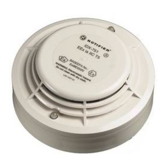
FOR MODEL IDX-751
INTELLIGENT PHOTO ELECTRONIC SMOKE SENSOR
GENERAL DESCRIPTION
Model IDX-751 is an intrinsically safe smoke detector that combines a photo electronic
sensing chamber with analogue addressable communications and is for use in hazardous
areas where potentially explosive atmospheres are likely to arise. The classification of
equipment required must be confirmed with your responsible authority. The sensor
communicates via a dedicated Galvanic Isolator Barrier with an IMX-1 / IST200 Translator
Module which relays the data to the Control Panel. Rotary decade switches are
provided for setting the sensor address.
Two LEDs on each sensor provide a local 360° visible sensor indication.
SPECIFICATIONS
Operating Voltage Range:
Max. Avg. Standby Current:
Max. Alarm Current (LED on):
Operating Humidity Range:
Intrinsic Safety Rating:
This detector has been independently tested and certified to EN54 part 7: 2000 and
BASEEFA approved for intrinsic safety.
ACCESSORIES (Available Separately from Notifier)
IMX-1 / IST200 Translator Module
Pepperl and Fuchs Y72221
WIRING GUIDE
Refer to the installation instructions supplied with the IMX-1/ IST200 Translator Module,
and B501AP Base for wiring details.
Note 1: All wiring must conform to applicable local and national codes and regulations.
Note 2:Verify that all sensor bases are installed and that polarity of the wiring is correct
at each base.
Disconnect loop power before installing sensors. Notify proper authorities.
SENSOR INSTALLATION
1. Set the sensor address (see figure 2) by turning the two rotary switches, selecting
a number between 01and 99. Record the address on the label attached to the base.
2. Insert the sensor into the base and rotate it clockwise until it locks into place.
3. After all the sensors have been installed, apply power to the system.
4. Test the sensor as described under TESTING.
5. Reset the sensor by communication command from the panel.
Figure 2: Rotary Decade Address Switch
6 7
8
5
4
3
2
1
0
Tamper-Resistance.
Model IDX-751 includes a feature that, when activated, prevents removal of the sensor
without the use of a tool. Refer to the installation instructions for the sensor base for
details of how to use this feature.
Dust covers help to protect units during shipping and when first installed. They
are not intended to provide complete protection against contamination therefore
sensors should be removed before construction, major re-decoration or other
dust producing work is started. Dust covers must be removed before system
can be made operational.
MAINTENANCE
Before cleaning, disable the system to prevent unwanted alarms:
1. Remove the sensor to be cleaned from the system.
2. Gently release each of the four cover removal tabs that hold the cover in place (see
figure 1) and remove the cover.
3. Vacuum the outside of the screen carefully without removing it.
4. Remove the sensor screen. Pull the screen straight away from the sensing chamber until
it snaps out of place.
5. Remove the chamber cover by pulling it gently away from the sensing chamber until
it snaps out of place.
6. Use a vacuum cleaner and/or clean, compressed air to remove dust and debris from
the sensing chamber and sensing chamber cover.
N200-51-00
IDX-751
60°C
112.5g
-20°C
T4
INTRINSICALLY SAFE
AE
15 to 24 VDC
220 µA @20 VDC (One communication every 5
sec. With LED blink enabled)
3 mA @ 24 VDC
10% to 93% Relative Humidity, Non-Condensing
o
o
Ex ia IIC T5 (40
to -20
C), T4 (60
May drive up to 15 IDX-751 sensors
Dedicated Galvanic Isolator Barrier for IDX-751
detector (drives up to 15 IDX-751 sensors).
WARNING
7
8
9
6
9
5
4
3
2
1
0
TENS
UNITS
CAUTION
Notifier Ltd. Charles Avenue, Burgess Hill, West Sussex, RH15 9UF, UK
AE
40°C
-20°C
T5
7. Re-install the sensing chamber cover by aligning the arrow moulded on the cover
with the arrow printed on the circuit board and sliding the cover over the chamber,
gently pressing it home until it snaps into place.
8. Re-install the sensing chamber screen by sliding it over the sensing chamber.
Rotate the screen until the locating tabs on the bottom rim locate in the cutouts in
the chamber base, and the top of the screen is flush with the top of the chamber.
9. Re-install the sensor cover. Use the cover removal tabs and LEDs to align the cover
with the sensor. Snap the cover into place.
10. When all sensors have been cleaned, restore power to the loop and test the
sensor(s) as described under TESTING.
The Detector has a plastic enclosure that may present an electrostatic risk and
must not be installed in a position where it may be subject to a high dust-laden
air flow. Clean only with a damp cloth and do not rub.
o
o
to -20
C)
TESTING
Sensors must be tested after installation and following periodic maintenance. Disable
the zone or system undergoing maintenance to prevent unwanted alarms.
If testing is carried out using non-intrinsically safe methods, it must be
Test the sensors as follows:
Magnet Test Method
1. Test the sensor by positioning the test magnet (model M02-24-optional) against the
sensor body approximately 2cm from LED 1, indicated by a mark on the detector
cover as shown in figure 3.
2. Both LED's on the detector should latch into alarm within 30 seconds, activating the
control panel.
LED 2
Test Magnet
Smoke Method
1. Using generated smoke, or synthetic smoke aerosol from an approved manufacturer
such as No Climb Products Ltd, subject the detector to controlled amounts of smoke
in accordance with local codes of practice and manufacturer recommendations.
2. Both LED's on the detector should latch into alarm within 30 seconds, activating the
control panel.
After completion of the test notify the proper authorities that the system is operational.
Smoke detectors must be used in conjunction with compatible equipment.
Smoke detectors will not sense fires which start where smoke does not reach the
detectors.
A detector may not detect a fire developing on another level of a building.
Smoke detectors also have sensing limitations. Consideration must be made of the
environment when selecting fire detectors.
Smoke detectors cannot last forever. Smoke detectors contain electronic parts. Even
though detectors are made to last over 10 years, any of these parts could fail at any
time. Therefore, test your smoke detector system at least semiannually. Clean and take
care of your smoke detectors regularly. Taking care of the fire detection system you
have installed will significantly reduce your product liability risks.
COVER
REMOVAL TABS
Figure 1:
Cleaning the Sensor
CAUTION
IMPORTANT
conducted outside the hazardous area.
Figure 3: Test Magnet Position
LED 1
Mark on Cover
WARNING
LIMITATIONS OF SMOKE DETECTORS
0832
SENSOR
0832-CPD-0201
COVER
SENSOR
SCREEN
SENSING
CHAMBER
I56-3383-002
Werbung

Verwandte Anleitungen für Notifier IDX-751 AE


Inhaltszusammenfassung für Notifier IDX-751 AE
- Seite 3 CHAMBER Rauchmelders MODELL IDX-751 EIGENSICHERER INTELLIGENTER OPTISCHER RAUCHMELDER Ex-KIT ST – Bausatz für die Anbindung einer Gruppe von Ex-Meldern für den Notifier Ringbus. WARTUNG Bitte beachten: Zur Vermeidung von Fehlalarmen sollte das System bzw. die entsprechende In Deutschland hergestellte Produkte werden mit dem IMX-1 Übersetzermodul und Meldergruppe vor den Wartungsarbeiten abgeschaltet werden.
- Seite 4 Ausgabedatum: 18/11/2008 Hersteller: Pittway Tecnologica S.r.l. Via Caboto 19/3, 34147 Trieste, Italy Produkt: IDX-751 AE Meldersockel: B501, B501AP Beschreibung: Eigensicherer Intelligenter Optischer Rauchmelder Wir bestätigen hiermit, dass die oben beschriebenen Produkte den Anforderungen der EMV-Richtlinie 89/336/EEC geändert durch die 92/31/ EEC, 93/68/EEC, 93/97/EEC und den unten aufgeführten Richtlinien entspricht.