RINGFEDER 2020 Montage- Und Betriebsanleitung
Verfügbare Sprachen
Verfügbare Sprachen
Mounting of the drawbar coupling on the vehicle type has to be made in
accordance with the requirements defined in annex VII of the directive 94/20
EC as described below
Easy and safe coupling operation
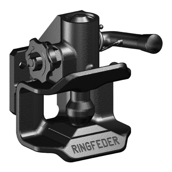
Drawbar couplings must be mounted on the vehicle type in such a manner that they
are easy and safe to operate. In addition to the function of opening (and closing, if
applicable) this also includes checking the position of the indicator for the closed and
secured position of the coupling pin and thus, of the drawbar coupling itself (by sight
and touch). In the area in which the person operating the coupling must stand, there
must be no points of possible danger such as sharp edges, corners, etc. inherent in the
design or they must be protected so that injury is unlikely. The way of escape from this
area must not be restricted or barred on either side by any attached objects.
Accessibility of the drawbar coupling
The distance between the centre of the coupling pin and the rear edge of the vehicle
body- work must not exceed 420 mm. However, the distance of 420 mm may be excee-
ded if technical necessity can be demonstrated:
1. a distance of up to 650 mm for vehicles with tipping bodies or rear-mounted equipment;
2. a distance of up to 1 320 mm if the unobstructed height is at least 1 150 mm;
3. car transporters with at least two loading levels when the trailer vehicle is not sepa-
rated from the towing vehicle in normal transport operation, provided easy and safe
actuation of the drawbar coupling is not adversely affected.
Clearance for the hand lever of 60 mm and 100 mm, respectively
In order to permit safe operation of drawbar couplings there must be adequate free
space around the hand lever. The dimensions of clearance given below are regarded as
sufficient. The dimensions are also applicable as appropriate for drawbar couplings
having
hand
levers
pointing downwards
or
of
a
different
design.
If one or more of these
rules regarding easy
and safe operation,
accessibility or clearan-
ce for the hand lever
cannot be met, a coup-
ling with a remote
control device must be
used.
Anhängekupplungen · Trailer Couplings
Ein zertifiziertes Unternehmen nach DIN EN ISO 9001 und VDA 6.1
A certified company in accordance with DIN EN ISO 9001 and VDA 6.1
VBG GROUP TRUCK EQUIPMENT GMBH · Oberschlesienstraße 15 · D-47807 Krefeld
Postfach/POB 13 06 55 · D-47758 Krefeld · Tel. +49 (0) 21 51 8 35-0 · Fax +49 (0) 21 51 8 35-200
www.ringfeder.de · info@ringfeder.de
10069174
08/2007

Verwandte Anleitungen für RINGFEDER 2020

Inhaltszusammenfassung für RINGFEDER 2020
- Seite 1 A certified company in accordance with DIN EN ISO 9001 and VDA 6.1 VBG GROUP TRUCK EQUIPMENT GMBH · Oberschlesienstraße 15 · D-47807 Krefeld Postfach/POB 13 06 55 · D-47758 Krefeld · Tel. +49 (0) 21 51 8 35-0 · Fax +49 (0) 21 51 8 35-200 www.ringfeder.de · info@ringfeder.de 10069174 08/2007...
- Seite 2 Montage- und Betriebsanleitung Installation and Operating Instructions Typ/Type 2020 10069174 08/2007...
- Seite 4 Stützlast 350 kg, Zul.V-Wert 18 kN, siehe Verwendungsbereich Die Verwendung der Anhängekupplung für einen D-Wert oder Dc-Wert von über 18 kN: Die Verwendung der Anhängekupplung Typ 2020 für einen D-Wert oder Dc-Wert von über 18 kN ist auf solche Kraftfahrzeuge beschränkt, bei denen die Verwendung die- ser Kupplung hinsichtlich größerer Fangmaulabmessungen aus technischen Gründen...
- Seite 5 Handhebel (3) nach oben drücken, bis er einrastet. Der Kuppelbolzen (8) ist nun oben, die Kupplung ist nun kuppelbereit. Zugfahrzeug langsam zurücksetzen. Durch das Einfahren der Zugöse wird der Kuppelbolzen angehoben und dadurch der Kuppelmechanismus ausgelöst.Der Kuppelbolzen schießt durch die Zugösenbuchse und wird in seiner untersten Endstellung in der Bohrung der unteren Führungsbuchse (Verschleißplatte 13) automatisch durch den gegen die Kuppelbolzenschräge sperren- den Sperrhebel (7) und den über dem Kuppelbolzen liegenden Sicherungsstift (14) der...
- Seite 6 Das EG-Typgenehmigungskennzeichen und die für die Anhängekupplung genehmig- ten Kennwerte sowie der Verwendungsbereich sind den Angaben auf dem Typenschild bzw. der zugehörigen Montage- und Betriebsanleitung zu entnehmen. Die für die Dimensionierung der Anhängekupplung erforderlichen Angaben des Zugfahrzeuges sind dem Fahrzeugbrief bzw Fahrzeugschein zu entnehmen. Bei nachträglichem Anbau oder Austausch der Anhängekupplung (Austausch einer anderen Anhängekupplung) sind in Deutschland die Vorschriften hinsichtlich der Berichtigung der Fahrzeugpapiere nach §...
- Seite 7 Überprüfung der zul. Anhängelast von Zugfahrzeug und Anhängekupplung hinsicht- lich der Berichtigung der Fahrzeugpapiere nach § 27StVZO in Deutschland Diese errechneten Werte, R für die Anhängelast der Anhängekupplung für den Betrieb mit Drehschemelanhängern und C für den Betrieb mit Starrdeichsel-/Zentralachsan- hängern, sind mit den sich aus den Eintragungen in den Fahrzeugpapieren ergeben- den Werten für die zul.
- Seite 8 Falls sich eine oder mehre- re Vorschriften bezüglich der leichten und sicheren Betätigung, der Erreich- barkeit oder des Hand- hebelfreiraumes nicht ein- halten lassen, muß eine Kupplung mit einer Ein- richtung zur Fernbetä- tigung verwendet wer- den. Anhängekupplung geöffnet: Handhebel oben Sicherungsstift steht über der Verriegelungshülse hervor Drawbar coupling opened:...