OSRAM DALI Switch SO Bedienungsanleitung
Quicklinks
DALI SWITCH SO / 3x6A / 24
DALI SWITCH SO / 3x6A / 24
EAN10 4008321533364
Bedien- und Montageanleitung
Operating and Mounting Instructions
Stand: April 2011, Rev. D
Issued: April 2011, Rev. D
A4
A4
A5
A6
A3
A1
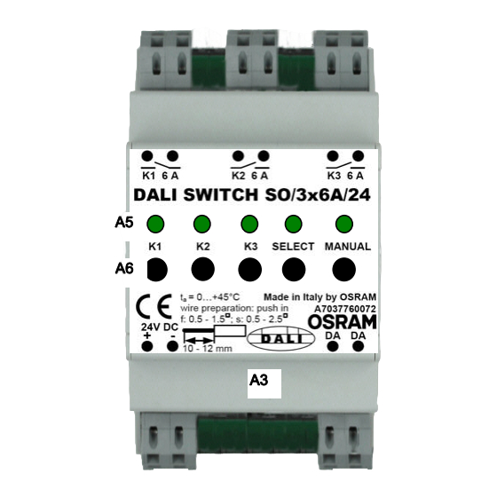
Bild 1 / figure 1
Installationsanweisung / Installation instructions
Bild 2: Montage (oben) und Demontage (unten)
figure 2: mounting (top) and dismount (bottom)
ZNN 2612749 000 00 Rev D
Produkt- und Funktionsbeschreibung
Der DALI SWITCH ist ein Ausgabegerät für den Schaltschrankein-
bau. Das Gerät ist zum Anschluss von nicht DALI-fähigen Lichtquel-
len bzw. Vorschaltgeräten an einem DALI Controller (z.B. OSRAM
DALI Professional) gedacht. Das Gerät hat 3 geschaltete Ausgänge.
Es können Verbraucher entsprechend max. 6 A / 230V ohmscher
Last angeschlossen werden. Das Gerät kann nur zusammen mit ei-
ner externen 24V DC Stromversorgung betrieben werden.
Die Schaltbefehle erhält der DALI SWITCH als Telegramme über die
DALI – Leitung vom DALI – Controller. Dabei verhält sich der DALI
SWITCH in der Grundeinstellung wie 3 getrennte DALI Schalter . Er
kann aber auch für alle 3 Ausgänge mit einer gemeinsamen Schalt-
funktion konfiguriert werden. Das Gerät entspricht dem DALI Stan-
dard IEC 62386-208 Switching Function / device type 7.
Verdrahtungsprüfung:
Bei angeschlossener Versorgungs –Spannung und einem langen Ta-
stendruck (>5s) auf die MANUAL – Taste leuchtet die MANUAL–
LED auf. Mit kurzem Tastendruck auf die TASTER K1..K3 kann das
A4
jeweilige Relais umgeschaltet werden. Die zugehörige LED K1..K3
zeigt dabei den Schaltzustand an. Wenn keine der Tasten innerhalb
von 30s bedient wird geht das Gerät wieder in den Grundzustand.
Eventuelle Änderungen der Schaltstellungen bleiben bestehen.
Auslieferzustand herstellen:
Bei angeschlossener Versorgungsspannung und einem langen Ta-
stendruck >10s auf die SELECT – Taste blinkt die SELECT – LED
für 4s und das Gerät wird in den Auslieferzustand zurückgesetzt.
Inbetriebnahme:
Das Gerät verhält sich im Auslieferungszustand wie 3 unabhängige
DALI Schalter. Um alle 3 Ausgänge als eine Schalterfunktion zu kon-
figurieren ist durch Kurzdruck auf die SELECT – Taste der Adress-
umschaltmodus zu aktivieren. Dann kann mit einem langen Druck
(>5s) auf die MANUAL – Taste zwischen 3 Einzeladressen (MANU-
AL– LED aus) und 1 Gesamtadresse (MANUAL– LED an) umge-
schaltet werden. ACHTUNG: Die Daten der beiden entfernten Ad-
ressen werden dabei gelöscht.
Identifikation:
Nach Aktivierung der 'Physical Selection' durch DALI Befehl bewirkt
A7
ein Druck auf eine der Tasten K1..K3 die Auswahl dieses Ausgangs.
Die zugehörige LED blinkt, das jeweilige Relais reagiert aber nicht.
Nun kann die Adressabfrage des gewählten Ausgangs erfolgen bzw.
eine Neuadressierung stattfinden. Nach Abschluss der Abfrage / Ad-
ressierung erlischt die zugehörige LED.Dieser Inbetriebnahmemodus
wird vom OSRAM DALI Professional Controllerunterstützt.
Anschlussbeispiel
siehe Bild 1
Lage und Funktion der Anzeige- und Bedienelemente
siehe Bild 1
A1
Versorgungs – Klemme (24V DC)
A2
DALI – Klemme
A3
Kunststoff – Gehäuse
A2
A4
Ausgangsklemmen Relais K1..K3
A5
LED K1..K3, SELECT,MANUAL
Tasten K1..K3, SELECT, MANUAL
A6
Frontabdeckung (Höhe 45mm)
A7
Installationshinweise
Das Gerät kann für feste Installation in trockenen Innenräumen, zum
Einbau in Schaltschränken verwendet werden.
WARNUNG
•
Das Gerät darf nur von einer zugelassenen Elektrofachkraft in-
stalliert und in Betrieb genommen werden.
•
Das Gerät muss mit 24V DC +/- 10% an Klemme A1 betrieben
werden. Keine Netzversorgung an die Klemme anschließen!
•
Die geltenden Sicherheits- und Unfallverhütungsvorschriften sind
zu beachten.
•
Das Gerät darf nicht geöffnet werden.
•
Bei der Planung und Errichtung von elektrischen Anlagen sind die
einschlägigen Richtlinien, Vorschriften und Bestimmungen des
jeweiligen Landes zu beachten.
•
Vor der Installation oder Wartungsarbeiten ist der Hauptschalter
der Anlage auszuschalten.
•
Der Monteur hat sicherzustellen, dass die Anschlussbereiche
ordnungsgemäß abgedeckt und nicht zugänglich sind. Um eine
ausreichende Sicherheit gegen versehentliches Berühren und
elektrostatische Entladung zu gewährleisten, darf kein Bereich mit
Ausnahme der Frontabdeckung (A7) zugänglich sein.
•
Die Relaisausgänge dürfen nicht parallel zur Erhöhung der maxi-
malen Last verdrahtet werden.
•
Das Gerät ist mit bistabilen Relais ausgestattet. Bei abgeschalte-
teter Versorgungsspannung darf nicht davon ausgegangen wer-
den daß alle Kontakte geöffnet sind.
•
Die Relaiskontakte sind bei Auslieferung standardmäßig ge-
schlossen. Es muss aber beachtet werden, dass mechanische
Stöße / Vibration während Transport, Installation oder im Betrieb
den Relaiszustand ändern können.
Montage
Allgemeine Beschreibung
Der DALI SWITCH wird auf die 35mm Hutschiene eines handelsübli-
chen Schaltschranks nach DIN 43880 aufgeschnappt / eingebaut
(Bild 2). Der Platzbedarf beträgt 3 Teilungseinheiten.
Anschlussklemmen
Die Anschlüsse des DALI SWITCH sind als Steckklemmen ausge-
führt. Die gesteckte Leitung kann mit Werkzeug wieder gelöst wer-
den.
D
Seite 1 von 2
GB
Product and Applications Description
The DALI SWITCH is a output device for installation into switch cabi-
nets. The device is made for connection of non-DALI lightsources or
ballasts to a DALI controller (e.g. OSRAM DALI Professional). The
device has 3 switched outputs. Devices which are equivalent to max.
6A / 230V ohmic load can be connected. The device can only be
used in combination with an external 24V DC supply.
The switching commands are received by the DALI SWITCH as tele-
grams via the DALI – line from DALI controller. The behaviour of
DALI SWITCH in the default setting is as 3 independent DALI
switches. A configuration with one common switch function for all 3
outputs can be set. The device is made according to DALI Standard
IEC 62386-208 Switching Function / device type 7.
Wiring check:
When supply voltage is connected, a long press (>5s) of the
MANUAL pushbutton will switch on the MANUAL– LED. With a short-
press of PUSHBUTTON K1..K3 the related relay can be switched.
The related LED K1..K3 signals the status. If no pushbutton is used
within 30s the unit will return into standard mode. If changes in relay
outputs were made these will remain.
Reset to factory default settings:
When supply voltage is connected a long press (>10s) on the
SELECT pushbutton will let blink the SELECT – LED for 4s and the
device will be reset to factory default settings.
Commissioning
The device default setting is 3 independent DALI switches. To con-
figurate all 3 outputs as one switch function activate the address
switching mode with the SELECT – pushbutton. After that by a long
press (>5s) of the MANUAL – pushbutton it can be switched between
3 single addresses (MANUAL– LED off) and 1 common address
(MANUAL– LED on). ATTENTION: With this the data of the 2 deleted
addresses will be lost.
Identification:
After activating the 'Physical Selection' by DALI command a press of
PUSHBUTTON K1..K3 will select this output. The according LED
flashes and the related relay will not switch. Now the address query
of the selected output or a new addressing can be made. After finish-
ing the query / addressing the LED will switch off. This identification
is supported by OSRAM DALI Professional Controller.
Example of Operation
see figure 1
Location and Function of the Display and Operating Elements
see figure 1
Supply – Terminals (24V DC)
A1
DALI – Terminals
A2
A3
Plastic housing
A4
Output – Terminals Relays K1..K3
A5
LEDs K1..K3, SELECT,MANUAL
A6
pushbuttons K1..K3, SELECT, MANUAL
A7
Front cover face (height 45 mm)
Installation Instructions
The device may be used for permanent interior installations in dry lo-
cations within switch cabinets.
WARNING
•
The device must be mounted and commissioned by an authorised
electrician.
•
The device must be supplied with 24V DC +/- 10% on terminals
A1. Do not apply mains line voltage to these terminals!
•
The prevailing safety and accident prevention rules must be
heeded.
•
The device must not be opened.
•
When planning and installing electrical installations, the relevant
guidelines, regulations and specifications of the respective coun-
try must be observed.
•
Before starting installation or maintenance work turn the main
switch of the installation off.
•
It must be ensured by the installer that the terminal connection
areas are properly covered and not accessible. To give sufficient
protection against accidental touching of live parts and electro-
static discharge, areas other than the front cover face (A7) must
be inaccessible.
•
The relays outputs must not be wired parallel to increase the
maximum load.
•
The device is equipped with bistable relays. When supply voltage
is disconnected it cannot be assumed that all relay contacts are
open.
•
Relay contacts are closed by default on shipping. Attention must
be paid since mechanical shocks / vibration during transport, in-
stallation and during operation could change the relay state.
Mounting
General description
The DALI SWITCH is intended to be snap/ mounted on a 35mm DIN
rail in a switch cabinet acc. DIN 43880 (figure 2). The required space
is 3 units.
Terminals
The connectionof DALI SWITCH are push-in type terminals. The
wires can be removed with a tool.
page 1 of 2

Verwandte Anleitungen für OSRAM DALI Switch SO

Inhaltszusammenfassung für OSRAM DALI Switch SO
- Seite 1 The device is made for connection of non-DALI lightsources or bau. Das Gerät ist zum Anschluss von nicht DALI-fähigen Lichtquel- ballasts to a DALI controller (e.g. OSRAM DALI Professional). The len bzw. Vorschaltgeräten an einem DALI Controller (z.B. OSRAM device has 3 switched outputs.
- Seite 2 • Power Supply 24V DC OSRAM PS30/100-240/24 OSRAM PS30/100-240/24 • DALI Controller • DALI Controller OSRAM DALI PROFESSIONAL CONTROLLER-4 OSRAM DALI PROFESSIONAL CONTROLLER-4 Allgemeine Hinweise General Notes • Die Bedienungsanleitung ist dem Kunden auszuhändigen. • The operating instructions must be handed over to the client.