Thermaltake Level 10 Benutzerhandbuch
Inhaltsverzeichnis
©2009 Thermaltake Technology Co., Ltd. All Rights Reserved. 2009.08
All other registered trademarks belong to their respective companies.
Tested To Comply
With FCC Standards
FOR HOME OR OFFICE USE
www.thermaltake.com
VL30001W1Z
User's Manual
Benutzerhandbuch
Mode d'emploi
Manual del usuario
Manuale dell'utente
安裝說明書
用戶手冊
ユーザーズマニュアル
Руководство пользователя
kullanıcı elkitabı
Inhaltsverzeichnis

Verwandte Anleitungen für Thermaltake Level 10


Inhaltszusammenfassung für Thermaltake Level 10
- Seite 1 Manual del usuario Manuale dell’utente 安裝說明書 用戶手冊 ユーザーズマニュアル Руководство пользователя kullanıcı elkitabı ©2009 Thermaltake Technology Co., Ltd. All Rights Reserved. 2009.08 All other registered trademarks belong to their respective companies. www.thermaltake.com Tested To Comply With FCC Standards FOR HOME OR OFFICE USE...
-
Seite 2: Inhaltsverzeichnis
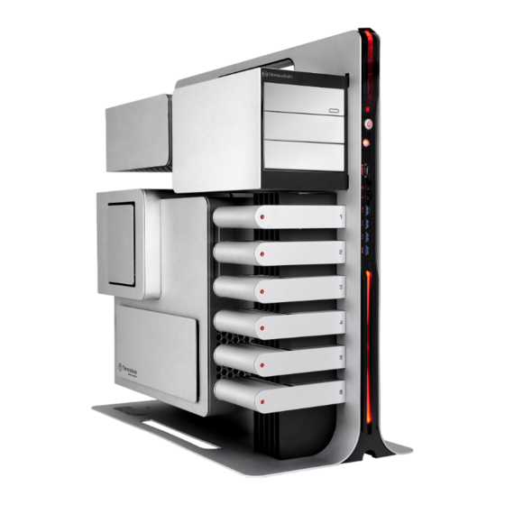
Chapter 1. Product Introduction Contents 1.1 Specification Chapter 1. Product Introduction Specification Product Name Level 10 VL30001N1Z Model Accessory Gaming Station Case Type CPU Cooler Height & VGA Dimension (D*W*H) 614 x 318 x 666.3 mm / 24.17 x 12.52 x 26.22 inch (Add-on card) Length Limitation 21.37 kg / 47.11 lb... -
Seite 3: (Add-On Card) Length Limitation
1.3 CPU Cooler Height.VGA (Add-on card) & PSU Length Limitation 警告!! CPU 冷卻器的高度限制: Waring!! 請確保 CPU 冷卻器的高度不超過 150 mm (5.91 英吋)。 CPU Cooler Height Limitation: VGA (附加介面卡) 的長度限制: Please ensure that your CPU cooler does NOT exceed 150mm (5.91 inches) height. 請確保... -
Seite 4: Chapter 2. Installation Guide
Chapter 2. Installation Guide 日本語 / Italiano / 2.1 Side Panel Disassembly 1. キーを使って、側面パネルのPSU/MB/SIDE 1. Ruotare l'incavo per la chiavetta del PANELのキー穴を「開放」位置まで回します. pannello laterale PSU/MB/SIDE PANEL in 2. キーを使って、側面パネルのODD/HDDのキー posizione OPEN (APERTO) usando la 穴を「ロック」位置まで戻します. chiave. 3. シャーシ側面パネルの裏側の上下蝶ねじを外し、 2. Ruotare di nuovo l'incavo per la chiavetta プレートを引っ張り出してパネルを開けます.。... -
Seite 5: Motherboard Installation
2.2 Motherboard Installation Español / 1. Gire la cerradura del panel lateral PSU/MB/ SIDE PANEL a la posición OPEN utilizando la llave. 2. Abra la cubierta de la placa madre. Italiano / 1. Ruotare l'incavo per la chiavetta del pannello laterale PSU/MB/SIDE PANEL in posizione OPEN (APERTO) usando la chiave. - Seite 6 Italiano / Italiano / 6. Posizionare il coperchio della scheda 4. Mettere la scheda madre in posizione e madre. fissarla con le viti e i cilindri in rame. 7. Ruotare di nuovo l'incavo per la 5. Posizionare il vano della scheda madre chiavetta del pannello laterale PSU/ all’interno e avvitare le quattro viti MB/SIDE PANEL in posizione LOCK...
-
Seite 7: Power Supply Installation
2.3 Power Supply Installation Italiano / Italiano / 1. Ruotare l'incavo per la chiavetta del 3. Svitare le due viti dal supporto pannello laterale PSU/MB/SIDE PANEL dell’alimentatore utilizzando il in posizione OPEN (APERTO) usando la cacciavite. chiave. 4. Rimuovere il supporto lungo i ganci. 2. - Seite 8 Italiano / 8. Fissare correttamente l’alimentatore. 9. Posizionare il coperchio dell’alimentatore. 10. Ruotare di nuovo l'incavo per la chiavetta del pannello laterale PSU/MB/SIDE PANEL in posizione LOCK (BLOCCO) usando la chiave. Italiano / 6. Posizionare l’alimentatore e fissarlo 繁體中文 / con le viti.
-
Seite 9: Device Installation
2.4 5.25” Device Installation Italiano / 1. Ruotare l'incavo per la chiavetta del pannello laterale ODD/HDD in posizione OPEN (APERTO) usando la chiave. 2. Aprire il coperchio del dispositivo da 5,25” e rimuoverlo. 繁體中文 / 1. 用鑰匙將側板ODD/HDD鎖孔轉開至 OPEN位置. 2. 轉開5.25”裝置外蓋並取下5.25”裝置外蓋. 简体中文... - Seite 10 Device Group 1 (Please screw at rear screw hole) 繁體中文 / 繁體中文 / English / English / 4. 將5.25”裝置插入插槽並用螺絲鎖上. 4. Insert the 5.25” device into the slot and 5. Put back the 5.25” device cover. 將5.25”裝置外蓋放回. screw the device. 简体中文 / Deutsche / Deutsche / 4.
- Seite 11 Device Group 2 and 3 (Please screw it at front screw hole) Italiano / 6. Dallo slot 2 o 3, svitare le viti dei fermi del dispositvo da 5,25” usando il cacciavite, quindi rimuovere i fermi. 繁體中文 / 用螺絲起子取下2或3槽的5.25”裝置檔片 螺絲並移除檔片. 简体中文...
- Seite 12 English / 繁體中文 / 9. Place the side panel back and lock it. 9. 將側板裝回並鎖上. 10.Turn the keyhole of the side panel ODD/ 10. 用鑰匙將側板ODD/HDD鎖孔轉開至 HDD into the OPEN position using the key. 繁體中文 / English / OPEN位置. 8. Put back the 5.25” device cover. 將5.25”裝置外蓋放回.
-
Seite 13: Hdd Device Installation
2.5 HDD Device Installation Italiano / 1. Ruotare l'incavo per la chiavetta del Italiano / pannello laterale ODD/HDD in posizione 11. Posizionare il coperchio del dispositivo OPEN (APERTO) usando la chiave. da 5,25”. 2. Estrarre il vano HDD e rimuoverlo. 12. - Seite 14 Italiano / 3. HDD 3,5”: Posizionarlo nel vano e Italiano / 4. HDD 2,5”: Posizionarlo nel vano e bloccare l’incavo della chiavetta bloccare l’incavo della chiavetta inferiore laterale utilizzando le viti. utilizzando le viti. 繁體中文 / 繁體中文 / 3.5”硬碟:硬碟放置拖盤上並用螺絲鎖上 2.5”硬碟:硬碟放置拖盤上並用螺絲鎖固底 側邊鎖孔.
- Seite 15 Italiano / 5. Fare scorrere di nuovo il vano nel supporto HDD. 6. Ruotare di nuovo l'incavo per la chiavetta del pannello laterale ODD/HDD in posizione LOCK (BLOCCATO) usando la chiave. 繁體中文 / 5. 將硬碟拖盤插回硬碟支架. 6. 用鑰匙將側板ODD/HDD鎖孔轉回 English / LOCK位置. (Note) Group 1 and 2 are designed for easy swappable purpose;...
-
Seite 16: Pci Slot Installation
2.6 PCI Slot Installation 2.7 Installation of Red LED Light Italiano / 1. Svitare le viti e rimuovere i fermi PCI. 2. Inserire il dispositivo PCI nell’apposito slot. Italiano / 3. Per terminare l’installazione, avvitare Inserire la spina da 4 pin dell’alimentatore il dispositivo. -
Seite 17: Chapter 3. Leads Installation Guide
Chapter 3. Leads Installation Guide... -
Seite 19: Chapter 4. Other
Chapter 4. Other Toughpower / Purepower / TR2 power supply series (optional) - Seite 20 Memo Memo...
- Seite 21 Memo Memo...
- Seite 22 Memo Memo...