Werbung
Verfügbare Sprachen
Verfügbare Sprachen
Quicklinks
USER INSTRUCTIONS
English
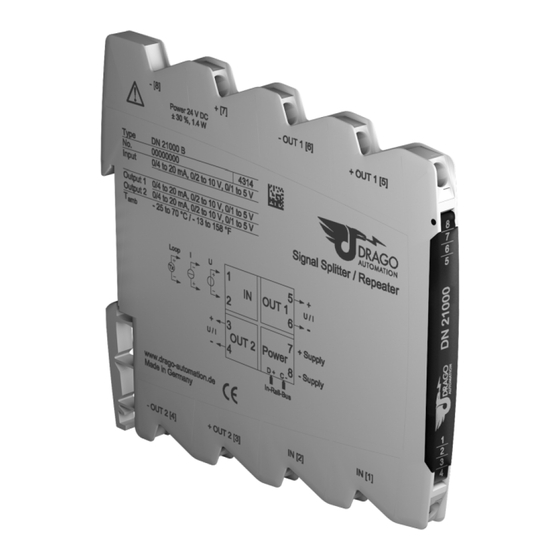
Signal Splitter / Repeater
DN 21000
Read these instructions before using the product and retain for future information.
DN 21000
► Before Startup
When operating the signal converter, certain parts
of the module can carry dangerous voltage!
Ignoring the warnings can lead to serious injury
and/or cause damage!
The signal converter should only be installed and
put into operation by qualified staff. The staff must
have studied the warnings in these operating
instructions thoroughly.
The signal converter may not be put into operation if
the housing is open.
In
applications
with
high
operating
voltages
sufficient distance and isolation as well as shock
protection must be ensured.
Safe and trouble-free operation of this device can
only be guaranteed if transport, storage and
installation are carried out correctly and operation
an maintenance are carried out with care.
Appropriate safety measures against electrostatic
discharge (ESD) should be taken during range
selection and assembly on the transmitter.
► Short description
The Signal Splitter/Repeater is used for isolation, conversion and
distribution of 0/4 ... 20 mA, 0/1 ... 5 V and 0/2 ... 10 V standard
signals. The measuring input can also supply the loop power for
2-wire transmitters.
The input and two isolated outputs can be easily configured by
using DIP switch. Due to the calibrated range selection no further
adjustment is necessary.
The 4-way isolation guarantees reliable decoupling of the sensor
circuit from the processing circuit and prevents linked measurement
circuits from influencing each other. The Protective Separation with
high isolation level
provides protection for personnel
downstream devices against impermissibly high voltage.
The auxiliary power can be supplied via the connection terminals or
type-specific
via
the
optional
In-Rail-Bus
connector
accessories). A green LED on the front of the unit has been provided
to monitor the power supply.
► Functioning
The input signal is modulated and then electrically decoupled using
a transformer. The isolated signal is then made available at the
output, demodulated, filtered and amplified.
► Settings
Set the input and output ranges with DIP switch as indicated in the
following table:
Range
Input
Output 1
Output 2
S1-
1
2
3
4
5
6
7
8
0...20 mA
●
●
4...20 mA
●
●
●
●
0...10 V
●
●
●
●
●
●
2...10 V
●
●
●
●
0...5 V
●
●
●
●
●
●
1...5 V
Loop Supply
●
Tx 0...20 mA
●
●
Tx 4...20 mA
Factory settings: all switches in position OFF
► Mounting, Electrical Connection
The repeater power supply is mounted on standard 35 mm DIN rail.
Terminal assignments
I −
1 Input
U +
Tx +
5 Output 1 U/I +
U −
Tx −
6 Output 1 U/I −
2 Input
I +
3 Output 2 U/I +
7 Power supply +
4 Output 2 U/I −
8 Power supply −
► Technical Data
Input
Current
Input signal
0 ... 20 mA
4 ... 20 mA
(calibrated switchable)
≤ 35 Ω
Input resistance
≤ 50 mA
Overload
2-wire Transmitter supply
16 V at 20 mA
(Tx, switchable)
(open circuit/short circuit < 22 V/35 mA)
Output 1 / Output 2
Current
Output signal
0 ... 20 mA
(calibrated switchable)
4 ... 20 mA
≤ 6 V (300 Ω at 20 mA)
Load
Linear transmission range
-1 to +110 %
Residual ripple
< 10 mV
and
rms
General data
Transmission error
< 0.1 % full scale
1)
Temperature coefficient
< 100 ppm/K
(see
Cut-off frequency -3 dB
5 kHz
Response time T
150 µs
99
Test voltage
3 kV, 50 Hz, 1 min. input against output I against
output II against power supply
2)
Working voltage
600 V AC/DC for overvoltage category II and
(Basic insulation)
contamination class 2 acc. to EN 61010-1
Protection against
Protective Separation by reinforced insulation acc.
dangerous body
to EN 61010-1 up to 300 V AC/DC for overvoltage
2)
category II and contamination class 2 between
currents
input and output and power supply.
Ambient temperature
Operation
Transport
and storage
Power supply
24 V DC
3)
EMC
EN 61326-1
Construction
6.2 mm (0.244'') housing, protection type: IP 20
mounting on 35 mm DIN rail acc. to EN 60715
Connection
Solid:
Fine-stranded:
(captive plus-minus
9
10
Stripped length: 6-8 mm / 0.28 in
clamp screws)
Screw terminal torque 0.8 Nm / 7 lbf in
●
Weight
Approx. 70 g
1) Average TC in specified operating temperature range
●
2) As far as relevant the standards and rules mentioned above are considered
●
by development and production of our devices. In addition relevant assembly
rules are to be considered by installation of our devices in other equipment.
●
●
For applications with high working voltages, take measures to prevent
accidental contact and make sure that there is sufficient distance or insulation
between adjacent situated devices.
3) Minor deviations possible during interference
● = on
► Block Diagram
► Order Information
Product
Input / Output
Signal Splitter/Repeater
calibrated
switchable
Signal Splitter/Repeater
calibrated
In-Rail-Bus for power supply
switchable
► Dimensions
Voltage
0 ... 10 V
0 ... 5 V
2 ... 10 V
1 ... 5 V
≥ 100 kΩ
≤ 30 V
Voltage
0 ... 10 V
0 ... 5 V
2 ... 10 V
1 ... 5 V
≤ 2 mA (5 kΩ at 10 V)
-25 °C to +70 °C (-13 to +158 °F)
-40 °C to +85 °C (-40 to +185 °F)
16.8 V ... 31.2 V, approx. 1.4 W
2
2
0.5 mm
- 4 mm
/ AWG 20-12
2
2
0.5 mm
- 2.5 mm
/ AWG 20-14
LIMITED WARRANTY
DRAGO Automation GmbH hereby warrants that the Product
will be free from defects in materials or workmanship for a
period of five (5) years from the date of delivery ("Limited
Warranty"). This Limited Warranty is limited to repair or
replacement at DRAGO's option and is effective only for the
first end-user of the Product. This Limited Warranty applies
only if the Product:
1. is installed according to the instructions furnished by DRAGO;
2. is connected to a proper power supply;
3. is not misused or abused; and
4. there is no evidence of tampering, mishandling, neglect,
accidental damage, modification or repair without the
approval of DRAGO or damage done to the Product by
anyone other than DRAGO.
Delivery conditions are based upon the „GENERAL
CONDITIONS FOR THE SUPPLY OF PRODUCTS AND
SERVICES OF THE ELECTRICAL AND ELECTRONICS
INDUSTRY",
recommended
Elektrotechnik- und Elektronikindustrie (ZVEI) e.V. .
Subject to change!
DRAGO Automation GmbH
Waldstrasse 86 - 90
Order No.
13403 BERLIN
DN 21000 S
GERMANY
DN 21000 B
Phone:
+49 (0)30 40 99 82 - 0
Fax:
+49 (0)30 40 99 82 - 10
E-Mail:
info@drago-automation.de
Internet: www.drago-automation.de
by
the
Zentralverband
Werbung

Inhaltszusammenfassung für Drago Automation DN 21000
- Seite 1 ● ● ● ● ● DRAGO Automation GmbH hereby warrants that the Product 1…5 V DN 21000 For applications with high working voltages, take measures to prevent will be free from defects in materials or workmanship for a Loop Supply accidental contact and make sure that there is sufficient distance or insulation period of five (5) years from the date of delivery (”Limited...
- Seite 2 BESCHRÄNKTE GARANTIE 2…10 V ● ● ● ● ● Herstellung unserer Produkte berücksichtigt, soweit sie anwendbar sind. Die DRAGO Automation GmbH garantiert hiermit, dass das 0…5 V Errichtungsbestimmungen sind beim Einbau unserer Produkte in Geräte und ● ● ● ● ●...