DeLOCK 86440 Gebrauchsanweisung
User manual
Gebrauchsanweisung
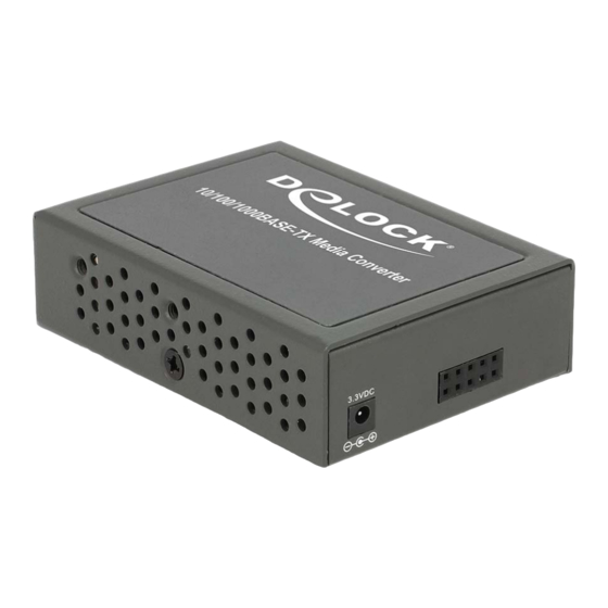
Media Converter 10/100/1000Base-T
to SFP compact
Description
The Delock Gigabit Ethernet Media Converter series is designed to
extend a copper based Ethernet network via fiber cable to a maximum
distance up to 80 km. The 10/100/1000 Mb/s Gigabit Ethernet Media
Converter series is fully compliant with IEEE802.3z and IEEE802.3ab
standards. The installation and operation procedures are simple and
straightforward. Operation status can be locally monitored through a
set of diagnostic LEDs located in the front panel.
Package content
• Media converter, power supply, user manual
Safety instructions:
1. This product is suitable for indoor application only.
2. Put on the dust cover of fiber interface when not used.
3. It is forbidden to stare at the TX fiber-transfer end with naked eyes.
Technical specifications
Function
Standard protocol
Connector
TP cable
Operation mode
Data rate
Power supply
Environmental
temperature
Relative humidity
Dimensions
Installation
• Fiber interface
Slide the optional SFP module into the SFP slot and push until you hear
a click. Connect a fiber cable from the SFP module to the fiber network.
The fiber connections must be matched - transmit socket to receive
socket, the TX, RX fiber cable must be paired at both ends.
• TP interface
Connect a TP cable from the 10/100/1000Base-T network to the RJ-45
port on the media converter.
• Power
Connect the power adapter to the media converter and check that the
PWR/STA LED lights up. The TP and F/O LEDs will light up when all
the cable connections are correctly installed.
Product-No:86440
User manual no:86440-a
www.delock.com
Description
IEEE802.3 10/100Base-TX
IEEE802.3z 1000Base-SX/LX
IEEE 802.3ab 1000Base-T
one RJ-45 connector
one SFP slot
Cat.5 UTP cable or better
full duplex mode or half duplex mode
Auto MDI/MDI-X support on RJ45 port
Fiber: 100 Mb/s or 1000 Mb/s
Copper: 10/100/1000 Mb/s
+3.3 V DC 2 A
0 °C ~ 50 °C
5 % ~ 90 %, non-condensing
ca. 74 mm x 51 mm x 20 mm
-
-
2
LED description
LED indicator lamps serve as device monitoring and troubleshooting
display. The following is the explanation for each LED indicator lamp.
Fig. 1: Front panel
LED
Status
Description
PWR/STA
Green
Lit when power is available
Green
Lit when TP cable connection with remote de-
TP
Green
Lit when Fiber cable connection at 100M with
remote device is good.
F/O
Orange
Lit when Fiber cable connection at 1000M with
remote device is good.
Green
Lit when TP works in Full-Duplex.
FDX
Not-Lit when TP works in Half-Duplex.
Green
Lit when TP works in 10M.
Lit when TP works in 100M.
SPD
Orange
Lit when TP works in 1000M.
DIP SWITCH Setting
The default setting for PIN 1 through 7 is ON. The PIN 8 is OFF.
Pin no.
Function
OFF
1
TP Auto-Negotiation
Disable
2
Manual TP speed
10M
3
Manual TP speed
N/A
4
Fiber Speed
Manual
5
Fiber Manual Speed
100M
6
F/O mode
Force
7
N/A
N/A
8
Link Alarm
Disable
NOTE:
1. Before changing TP speed, please make sure PIN 1 is set to OFF.
2. When TP speed is set to 10M or 100M manually, PIN 3 needs to be
turned OFF.
3. Under 1000Mbps, it supports full-duplex mode only.
-
-
3
ON
Enable
100M
1000M
Auto-Sensing
1000M
Auto
N/A
Enable

Verwandte Anleitungen für DeLOCK 86440


Inhaltszusammenfassung für DeLOCK 86440
- Seite 1 LED description Description LED indicator lamps serve as device monitoring and troubleshooting The Delock Gigabit Ethernet Media Converter series is designed to Media Converter 10/100/1000Base-T display. The following is the explanation for each LED indicator lamp. extend a copper based Ethernet network via fiber cable to a maximum distance up to 80 km.
- Seite 2 Beschreibung der LEDs Kurzbeschreibung Die eingebauten LEDs dienen zur Überwachung und zur Fehlerdiagnose. Mit der Delock Gigabit Ethernet Medien Konverter Serie können Sie www.delock.com Ihr Gigabit Ethernet Netzwerk um einen Lichtwellenleiter Anschluss mit einer maximalen Reichweite von bis zu 80 km erweitern. Die...