Herunterladen Inhalt Inhalt Diese Seite drucken
Inhaltsverzeichnis

Werbung

Verfügbare Sprachen

Verfügbare Sprachen

Quick Start
®
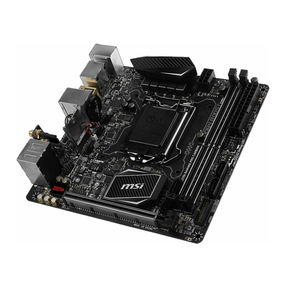
Thank you for purchasing the MSI
Z270I GAMING PRO CARBON
AC
motherboard. This Quick Start section provides demonstration
diagrams about how to install your computer. Some of the
installations also provide video demonstrations. Please link to the
URL to watch it with the web browser on your phone or tablet. You
may have even link to the URL by scanning the QR code.
Kurzanleitung
®
Danke, dass Sie das MSI
Z270I GAMING PRO CARBON AC
Motherboard gewählt haben. Dieser Abschnitt der Kurzanleitung
bietet eine Demo zur Installation Ihres Computers. Manche
Installationen bieten auch die Videodemonstrationen. Klicken Sie
auf die URL, um diese Videoanleitung mit Ihrem Browser auf Ihrem
Handy oder Table anzusehen. Oder scannen Sie auch den QR Code
mit Ihrem Handy, um die URL zu öffnen.
Présentation rapide
®
Merci d avoir choisi la carte mère MSI
Z270I GAMING PRO CARBON
AC. Ce manuel fournit une rapide présentation avec des illustrations
explicatives qui vous aideront à assembler votre ordinateur. Des
tutoriels vidéo sont disponibles pour certaines étapes. Cliquez sur
le lien fourni pour regarder la vidéo sur votre téléphone ou votre
tablette. Vous pouvez également accéder au lien en scannant le QR
code qui lui est associé.
®
MSI
Z270I
GAMING PRO CARBON
AC.
,
.
.
,
-
.
,
QR-
.
I
Quick Start

Werbung

Inhaltsverzeichnis
loading

Inhaltszusammenfassung für MSI Z270I GAMING PRO CARBON AC

  • Seite 1 Ihrem Handy, um die URL zu öffnen. Présentation rapide ® Merci d avoir choisi la carte mère MSI Z270I GAMING PRO CARBON AC. Ce manuel fournit une rapide présentation avec des illustrations explicatives qui vous aideront à assembler votre ordinateur. Des tutoriels vidéo sont disponibles pour certaines étapes.
  • Seite 2 Installing a Processor/ Installation des Prozessors/ Installer un processeur/ http://youtu.be/bf5La099urI Quick Start...
  • Seite 3 Installing DDR4 memory/ Installation des DDR4-Speichers/ Installer une mémoire DDR4/ DDR4 http://youtu.be/T03aDrJPyQs Quick Start...
  • Seite 4 Connecting the Front Panel Header/ Anschließen der Frontpanel-Stiftleiste/ Connecter un connecteur du panneau avant/ http://youtu.be/DPELIdVNZUI HDD LED + Power LED + HDD LED - Power LED - Reset Switch Power Switch Reset Switch Power Switch JFP1 Reserved No Pin JFP1 HDD LED - HDD LED HDD LED +...
  • Seite 5 Installing the Motherboard/ Installation des Motherboards/ Installer la carte mère/ Quick Start...
  • Seite 6 Installing SATA Drives/ Installation der SATA-Laufwerke/ Installer le disque dur SATA/ SATA Quick Start...
  • Seite 7 Installing a Graphics Card/ Einbau der Grafikkarte/ Installer une carte graphique/ Quick Start...
  • Seite 8 Connecting Peripheral Devices/ Peripheriegeräte/ Connecter un périphérique anschliessen/ VIII Quick Start...
  • Seite 9 Connecting the Power Connectors/ Stromanschlüsse anschliessen/ Connecter les câbles du module d alimentation/ ATX_PWR1 CPU_PWR1 Quick Start...
  • Seite 10: Power On/ Einschalten/ Mettre Sous-Tension

    Power On/ Einschalten/ Mettre sous-tension/ Quick Start...
  • Seite 11: Inhaltsverzeichnis

    Contents Safety Information ....................2 Specifications ......................3 Rear I/O Panel ....................... 8 LAN Port LED Status Table..................8 Audio Ports Configuration ..................8 Realtek HD Audio Manager ..................9 Overview of Components ..................11 M2_1: M.2 Slot (Key M) ..................12 CPU Socket ......................
  • Seite 12: Safety Information

    Safety Information The components included in this package are prone to damage from electrostatic discharge (ESD). Please adhere to the following instructions to ensure successful computer assembly. Ensure that all components are securely connected. Loose connections may cause the computer to not recognize a component or fail to start. Hold the motherboard by the edges to avoid touching sensitive components.
  • Seite 13: Specifications

    Supports non-ECC, un-buffered memory ® Supports Intel Extreme Memory Profile (XMP) * Please refer to www.msi.com for more information on compatible memory. Expansion Slots 1x PCIe 3.0 x16 slot 1x HDMI™ port, supports a maximum resolution of 4096x2160@30Hz (7th CPU), 4096x2160@24Hz (6th CPU),...
  • Seite 14 Continued from previous page ASMedia ® ASM2142 Chipset ƒ 1x USB 3.1 Gen2 (SuperSpeed USB 10Gbps) Type-C port on the back panel ƒ 1x USB 3.1 Gen2 (SuperSpeed USB 10Gbps) Type-A port on the back panel Intel ® Z270 Chipset ƒ...
  • Seite 15 UEFI AMI BIOS BIOS Features ACPI 5.0, PnP 1.0a, SM BIOS 2.8 Multi-language Drivers SUPER CHARGER FAST BOOT COMMAND CENTER LIVE UPDATE 6 MSI SMART TOOL DRAGON EYE GAMING APP Software X-BOOST RAMDISK GAMING LAN MANAGER Nahimic Audio XSplit Gamecaster V2...
  • Seite 16 GAMING CERTIFIED WTFast GPN* ƒ 2-Month Premium License ƒ Multi-Server Network Optimization ƒ Advanced Lag Spike & Disconnect Reduction * This offer is valid for a limited period only, for more information please visit www.msi.com Continued on next page Specifications...
  • Seite 17 ESD Protection ˜ EMI Protection ˜ Humidity Protection ˜ Circuit Protection ˜ High Temperature Protection ˜ VGA Armor Slot MSI Steel Armor MSI Exclusive ƒ Features PCI-E Steel Armor ƒ DDR4 Steel Shielding COMMAND CENTER ƒ System Monitor ƒ Smart Fan Control MYSTIC LIGHT EXTENSION ƒ...
  • Seite 18: Rear I/O Panel

    Rear I/O Panel Antenna Connectors Audio Ports PS/2 Port USB 3.1 Gen2 DisplayPort USB 2.0 USB 3.1 Gen2 Type-C Clear CMOS button USB 3.1 Gen1 Optical S/PDIF-Out Clear CMOS button - Power off your computer. Press and hold the Clear CMOS button for about 5-10 seconds to reset BIOS to default values.
  • Seite 19: Realtek Hd Audio Manager

    Realtek HD Audio Manager After installing the Realtek HD Audio driver, the Realtek HD Audio Manager icon will appear in the system tray. Double click on the icon to launch. Device Selection Advanced Settings Jack Status Application Enhancement Main Volume Connector Strings Profiles...
  • Seite 20 Audio jacks to headphone and microphone diagram Audio jacks to stereo speakers diagram AUDIO INPUT Audio jacks to 7.1-channel speakers diagram AUDIO INPUT Rear Front Side Center/ Subwoofer Rear I/O Panel...
  • Seite 21: Overview Of Components

    Overview of Components TOP View SYS_FAN2 CPU_PWR1 DIMMA1 DIMMB1 CPU Socket CPU_FAN1 ATX_PWR1 JCI1 JFP1 JFP2 SYS_FAN1 M2_2 SATA4 JLED1 SATA3 JBAT1 SATA1 JUSB2 JAUD1 SATA2 JUSB1 JTPM1 PCI_E1 Bottom View M2_1 Overview of Components...
  • Seite 22: M2_1: M.2 Slot (Key M)

    M2_1: M.2 Slot (Key M) The M.2 slot is on the bottom of the motherboard, which supports 2242/ 2260/ 2280 length M.2 storage devices only. Important Before you install the motherboard into the case, make sure your M.2 module has been installed properly. Intel ®...
  • Seite 23: Cpu Socket

    Always unplug the power cord from the power outlet before installing or removing the CPU. Please retain the CPU protective cap after installing the processor. MSI will deal with Return Merchandise Authorization (RMA) requests if only the motherboard comes with the protective cap on the CPU socket.
  • Seite 24: Dimm Slots

    DIMM Slots DIMMA1 DIMMB1 Channel A Channel B Important Due to chipset resource usage, the available capacity of memory will be a little less than the amount of installed. Based on Intel CPU specification, the Memory DIMM voltage below 1.35V is suggested to protect the CPU.
  • Seite 25: Pci_E1: Pcie Expansion Slot

    Important If you install a large and heavy graphics card, you need to use a tool such as MSI Gaming Series Graphics Card Bolster to support its weight and to prevent deformation of the slot. When adding or removing expansion cards, always turn off the power supply and unplug the power supply power cable from the power outlet.
  • Seite 26: Cpu_Pwr1, Atx_Pwr1: Power Connectors

    CPU_PWR1, ATX_PWR1: Power Connectors These connectors allow you to connect an ATX power supply. CPU_PWR1 Ground +12V Ground +12V Ground +12V Ground +12V +3.3V +3.3V +3.3V -12V Ground Ground PS-ON# Ground Ground Ground ATX_PWR1 Ground Ground PWR OK 5VSB +12V +12V +3.3V Ground...
  • Seite 27: Jusb1: Usb 2.0 Connector

    JUSB1: USB 2.0 Connector This connector allows you to connect USB 2.0 ports on the front panel. USB0- USB1- USB0+ USB1+ Ground Ground No Pin Important Note that the VCC and Ground pins must be connected correctly to avoid possible damage.
  • Seite 28: Cpu_Fan1,Sys_Fan1~2: Fan Connectors

    CPU_FAN1,SYS_FAN1~2: Fan Connectors Fan connectors can be classified as PWM (Pulse Width Modulation) Mode and DC Mode. PWM Mode fan connectors provide constant 12V output and adjust fan speed with speed control signal. DC Mode fan connectors control fan speed by changing voltage.
  • Seite 29: Jaud1: Front Audio Connector

    JAUD1: Front Audio Connector This connector allows you to connect audio jacks on the front panel. MIC L Ground MIC R Head Phone R MIC Detection SENSE_SEND No Pin Head Phone L Head Phone Detection JCI1: Chassis Intrusion Connector This connector allows you to connect the chassis intrusion switch cable. Normal Trigger the chassis intrusion event...
  • Seite 30: Jtpm1: Tpm Module Connector

    JTPM1: TPM Module Connector This connector is for TPM (Trusted Platform Module). Please refer to the TPM security platform manual for more details and usages. LPC Clock 3V Standby power LPC Reset 3.3V Power LPC address & data pin0 Serial IRQ LPC address &...
  • Seite 31: Jled1: Rgb Led Connector

    JLED1: RGB LED connector This connector allows you to connect the 5050 RGB LED strips. +12V 5050 LED strip Extension cable JLED1 Important This connector supports 5050 RGB multi-color LED strips (12V/G/R/B) with the maximum power rating of 3A (12V). Please keeping the LED strip shorter than 2 meters to prevent dimming.
  • Seite 32: Onboard Leds

    Onboard LEDs EZ Debug LEDs These LEDs indicate the status of key components during booting process. When an error is occurred, the corresponding LED stays lit until the problem is solved.. CPU - indicates CPU is not detected or fail. DRAM - indicates DRAM is not detected or fail.
  • Seite 33: Bios Setup

    Press Delete key, when the Press DEL key to enter Setup Menu, F11 to enter Boot Menu message appears on the screen during the boot process. Use MSI FAST BOOT application. Click on GO2BIOS button and choose OK. The system will reboot and enter BIOS setup directly.
  • Seite 34: Resetting Bios

    Updating BIOS Updating BIOS with M-FLASH Before updating: Please download the latest BIOS file that matches your motherboard model from MSI website. And then save the BIOS file into the USB flash drive. Updating BIOS: Press Del key to enter the BIOS Setup during POST.
  • Seite 35: Ez Mode

    EZ Mode At EZ mode, it provides the basic system information and allows you to configure the basic setting. To configure the advanced BIOS settings, please enter the Advanced Mode by pressing the Setup Mode switch or F7 function key. Screenshot XMP switch Setup Mode switch...
  • Seite 36 Information display - click on the CPU, Memory, Storage, Fan Info and Help buttons on left side to display related information. Function buttons - enable or disable the LAN Option ROM, M.2 GENIE, HD audio controller, AHCI, RAID, CPU Fan Fail Warning Control and BIOS Log Review by clicking on their respective button.
  • Seite 37: Advanced Mode

    Advanced Mode Press Setup Mode switch or F7 function key can switch between EZ Mode and Advanced Mode in BIOS setup. Screenshot XMP switch Setup Mode switch Search Language System information GAME BOOST switch Boot device priority bar BIOS menu BIOS menu selection selection...
  • Seite 38: Oc Menu

    OC Menu This menu is for advanced users who want to overclock the motherboard. Important Overclocking your PC manually is only recommended for advanced users. Overclocking is not guaranteed, and if done improperly, it could void your warranty or severely damage your hardware. If you are unfamiliar with overclocking, we advise you to use GAME BOOST function for easy overclocking.
  • Seite 39 CPU Ratio Mode [Dynamic Mode]* Selects the CPU Ratio operating mode. This item will appear when you set the CPU ratio manually. [Fixed Mode] Fixes the CPU ratio. [Dynamic Mode] CPU ratio will be changed dynamically according to the CPU loading.
  • Seite 40 Extreme Memory Profile (X.M.P.) [Disabled] X.M.P. (Extreme Memory Profile) is the overclocking technology by memory module. Please enable XMP or select a profile of memory module for overclocking the memory. This item will be available when the memory modules that support X.M.P. is installed. DRAM Reference Clock [Auto]* Sets the DRAM reference clock.
  • Seite 41 CPU Specifications Press Enter to enter the sub-menu. This sub-menu displays the information of installed CPU. You can also access this information menu at any time by pressing [F4]. Read only. fCPU Technology Support Press Enter to enter the sub-menu. The sub-menu shows the key features of installed CPU.
  • Seite 42 fHardware Prefetcher [Enabled] Enables or disables the hardware prefetcher (MLC Streamer prefetcher). [Enabled] Allows the hardware prefetcher to automatically pre-fetch data and instructions into L2 cache from memory for tuning the CPU performance. [Disabled] Disables the hardware prefetcher. fAdjacent Cache Line Prefetch [Enabled] Enables or disables the CPU hardware prefetcher (MLC Spatial prefetcher).
  • Seite 43 fEIST [Enabled] ® Enables or disables the Enhanced Intel SpeedStep Technology. This item will appear when OC Explore Mode is set to Normal. [Enabled] Enables the EIST to adjust CPU voltage and core frequency dynamically. It can decrease average power consumption and average heat production.
  • Seite 44: Software Description

    Insert the Windows 7/ 8.1/ 10 disc into your optical drive. Note: Due to chipset limitation, during the Windows 7 installation process, USB optical drives or USB flash drives are not supported. You can use MSI Smart Tool ® to install Windows Press the Restart button on the computer case.
  • Seite 45 Inhalt Sicherheitshinweis ....................2 Spezifikationen ...................... 3 Rückseite E/A ......................8 LAN Port LED Zustandstabelle ................8 Konfiguration der Audioanschlüsse ............... 8 Realtek HD Audio Manager ..................9 Übersicht der Komponenten ................11 M2_1: M.2 Steckplatz (Key M) ................12 CPU Sockel ......................
  • Seite 46: Sicherheitshinweis

    Sicherheitshinweis Die im Paket enthaltene Komponenten sind der Beschädigung durch elektrostatischen Entladung (ESD). Beachten Sie bitte die folgenden Hinweise, um die erfolgreichen Computermontage sicherzustellen. Stellen Sie sicher, dass alle Komponenten fest angeschlossen sind. Lockere Steckverbindungen können Probleme verursachen, zum Beispiel: Der Computer erkennt eine Komponente nicht oder startet nicht.
  • Seite 47: Spezifikationen

    2400(OC)/ 2133 MHz* Dual-Kanal-Speicherarchitektur Unterstützt ungepufferte non-ECC-Speicher ® Unterstützt Intel Extreme Memory Profile (XMP) * Weitere Informationen zu kompatiblen Speicher finden Sie unter: http://www.msi.com . Erweiterung- 1x PCIe 3.0 x16 Steckplatz anschlüsse 1x HDMI ™ Anschluss, Unterstützung einer maximalen Auflösung von 4096x2160@30Hz (Intel CPU, 7. Gen.), 4096x2160@24Hz (Intel CPU, 6.
  • Seite 48 Fortsetzung der vorherigen Seite ASMedia ® ASM2142 Chipsatz ƒ 1x USB 3.1 Gen2 (SuperSpeed USB 10Gbps) Typ-C Anschluss an der rückseitigen Anschlussleiste ƒ 1x USB 3.1 Gen2 (SuperSpeed USB 10Gbps) Typ-A Anschluss an der rückseitigen Anschlussleiste Intel ® Z270 Chipsatz ƒ...
  • Seite 49 UEFI AMI BIOS BIOS Funktionen ACPI 5.0, PnP 1.0a, SM BIOS 2.8 Mehrsprachenunterstützung Treiber SUPER CHARGER FAST BOOT COMMAND CENTER LIVE UPDATE 6 MSI SMART TOOL DRAGON EYE GAMING APP Software X-BOOST RAMDISK GAMING LAN MANAGER Nahimic Audio XSplit Gamecaster V2...
  • Seite 50 XSplit BROADCASTER GAMING CERTIFIED WTFast GPN* ƒ 2-Monate Premiumlizenz ƒ Multiserver-Netzwerkoptimierung ƒ Verbesserte Reduktion von Lag Spikes & Verbindungseinbrüchen * Dieses Angebot steht nur für begrenzte Zeit zur Verfügung, weitere Informationen finden Sie unter www.msi.com Fortsetzung auf der nächsten Seite Spezifikationen...
  • Seite 51 Military Class Stabilität und Zuverlässigkeit ˜ ESD-Schutz ˜ EMI-Schutz ˜ Luftfeuchtigkeit Schutz ˜ Schaltkreisschutz ˜ Übertemperaturschutz ˜ VGA Armor Steckplatz MSI Steel Armor MSI Exklusive ƒ Merkmale PCI-E Steel Armor ƒ DDR4 Steel Shielding COMMAND CENTER ƒ System-Monitor ƒ Smart-Lüftersteuerung MYSTIC LIGHT EXTENSION ƒ...
  • Seite 52: Rückseite E/A

    Rückseite E/A Antennenanschlüsse Audioanschlüsse PS/2 Anschluss USB 3.1 Gen2 DisplayPort USB 2.0 USB 3.1 Gen2 Typ-C Clear CMOS Taste USB 3.1 Gen1 Optischer S/PDIF-Ausgang Clear CMOS Taste - Schalten Sie den Computer aus. Halten Sie die Taste „Clear CMOS für 5-10 Sekunden gedrückt, um das BIOS auf die Standardwerte zurückzusetzen.
  • Seite 53: Realtek Hd Audio Manager

    Realtek HD Audio Manager Nach der Installation des Realtek HD Audio-Treibers, wird das Symbol Realtek HD Audio Manager in der Taskleiste angezeigt. Klicken Sie doppelt auf dieses Symbol, um das Programm zu starten. Geräteauswahl Erweiterte Einstellungen Verbindungs- status Optimierungen Lautstärke Anschlüsse Profil Geräteauswahl - Ermöglicht die Auswahl der Audio-Ausgangs Quelle.
  • Seite 54 Audiobuchsen für den Anschluss von einem Kopfhörer und Mikrofon Audiobuchsen für Stereo-Lautsprecher AUDIO INPUT Audiobuchsen für 7.1 Kanal Anlage AUDIO INPUT Rear Front Side Center/ Subwoofer Rückseite E/A...
  • Seite 55: Übersicht Der Komponenten

    Übersicht der Komponenten Obenansicht SYS_FAN2 CPU_PWR1 DIMMA1 DIMMB1 CPU Sockel CPU_FAN1 ATX_PWR1 JCI1 JFP1 JFP2 SYS_FAN1 M2_2 SATA4 JLED1 SATA3 JBAT1 SATA1 JUSB2 JAUD1 SATA2 JUSB1 PCI_E1 JTPM1 Unteransicht M2_1 Übersicht der Komponenten...
  • Seite 56: M2_1: M.2 Steckplatz (Key M)

    M2_1: M.2 Steckplatz (Key M) Der M2-Steckplatz befindet sich auf der Unterseite des Motherboards, er unterstützt ausschließlich M.2-Speicher mit den Längen 2242/2260/2280. Wichtig Bevor Sie das Motherboard in das Gehäuse installieren, stellen Sie sicher, dass das M.2-Modul korrekt eingebaut wurde. ®...
  • Seite 57: Cpu Sockel

    Sie jedoch bitte sicher, dass die betroffenen Komponenten mit den abweichenden Einstellungen während des Übertaktens zurecht kommen. Von jedem Versuch des Betriebes außerhalb der Produktspezifikationen kann nur abgeraten werden. MSI übernehmt keinerlei Garantie für die Schäden und Risiken, die aus einem unzulässigem Betrieb oder einem Betrieb außerhalb der Produktspezifikation resultieren.
  • Seite 58: Dimm-Steckplätze

    DIMM-Steckplätze DIMMA1 DIMMB1 Kanal A Kanal B Wichtig Aufgrund der Chipsatzressourcennutzung wird die verfügbare Kapazität des Speichers kleiner sein als die Größe der installierten Speicherkapazität. Basierend auf der Intel CPU Spezifikation wird eine Speicherspannung unter 1,35 Volt vorgeschlagen, um die CPU zu schützen. Bitte beachten Sie, dass die maximale Kapazität eines 32-Bit-Windows- Betriebssystem bei 4GB oder weniger liegt.
  • Seite 59: Pci_E1: Pcie Erweiterungssteckplatz

    PCI_E1: PCIe Erweiterungssteckplatz Wichtig Wenn Sie eine große und schwere Grafikkarte einbauen, benötigen Sie einen Grafikkarten-Stabilisator (Graphics Card Bolster) der das Gewicht trägt und eine Verformung des Steckplatzes vermeidet. Achten Sie darauf, dass Sie den Strom abschalten und das Netzkabel aus der Steckdose herausziehen, bevor Sie eine Erweiterungskarte installieren oder entfernen.
  • Seite 60: Cpu_Pwr1, Atx_Pwr1: Stromanschlüsse

    CPU_PWR1, ATX_PWR1: Stromanschlüsse Mit diesen Anschlüssen verbinden Sie die ATX Stromstecker. CPU_PWR1 Ground +12V Ground +12V Ground +12V Ground +12V +3.3V +3.3V +3.3V -12V Ground Ground PS-ON# Ground Ground Ground ATX_PWR1 Ground Ground PWR OK 5VSB +12V +12V +3.3V Ground Wichtig Stellen Sie sicher, dass alle Anschlüsse mit den richtigen Anschlüssen des Netzteils verbunden sind, um einen stabilen Betrieb der Hauptplatine sicherzustellen.
  • Seite 61: Jusb1: Usb 2.0 Anschluss

    Bitte beachten Sie, dass Sie die mit VCC (Stromführende Leitung) und Ground (Erdleitung) bezeichneten Pins korrekt verbinden müssen, ansonsten kann es zu Schäden kommen. Um das iPad, iPhone und den iPod über USB-Anschlüsse aufzuladen, installieren Sie bitte die MSI ® SUPER CHARGER Software. JUSB2: USB 3.1 Gen1 Anschluss Mit diesem Anschluss können Sie die USB 3.1 Gen1 Anschlüsse auf dem Frontpanel...
  • Seite 62: Cpu_Fan1,Sys_Fan1~2: Stromanschlüsse Für Lüfter

    CPU_FAN1,SYS_FAN1~2: Stromanschlüsse für Lüfter Diese Anschlüsse können im PWM (Pulse Width Modulation) Modus oder Spannungsmodus betrieben werden. Im PWM-Modus bieten die Lüfteranschlüsse konstante 12V Ausgang und regeln die Lüftergeschwindigkeit per Drehzahlsteuersignal. Im DC-Modus bestimmen die Lüfteranschlüsse die Lüftergeschwindigkeit durch Ändern der Spannung. Wenn Sie ein 3-Pin (Non-PWM) Lüfter an einen PWM-Modus Lüfteranschluss anschließen, läuft der Lüfter mit höchster Drehzahl und kann unangenehm laut werden.
  • Seite 63: Jaud1: Audioanschluss Des Frontpanels

    JAUD1: Audioanschluss des Frontpanels Dieser Anschluss ermöglicht den Anschluss von Audiobuchsen eines Frontpanels. MIC L Ground MIC R Head Phone R MIC Detection SENSE_SEND No Pin Head Phone L Head Phone Detection JCI1: Gehäusekontaktanschluss Dieser Anschluss wird mit einem Kontaktschalter verbunden. Normal Löse den Gehäuseeingriff aus...
  • Seite 64: Jtpm1: Tpm Anschluss

    JTPM1: TPM Anschluss Dieser Anschluss wird für das TPM Modul (Trusted Platform Module) verwendet. Weitere Informationen über den Einsatz des optionalen TPM Modules entnehmen Sie bitte dem TPM Plattform Handbuch. LPC Clock 3V Standby power LPC Reset 3.3V Power LPC address & data pin0 Serial IRQ LPC address &...
  • Seite 65: Jled1: Rgb Led Anschluss

    JLED1: RGB LED Anschluss Mit diesen Anschlüssen können Sie den 5050 RGB-LED-Streifen anschließen. +12V 5050 LED Streifen Verlängerungskabel JLED1 Wichtig Dieser Anschluss unterstützt die 5050 RGB Mehr-Farb-LED-Streifen (12V/R/G/B) mit der maximalen Leistung von 3A (12V). Beachten Sie bitte, dass die Länge des LED-Streifens maximal 2 Meter betragen darf um eine Verdunkelung der LED zu verhindern.
  • Seite 66: Onboard-Leds

    Onboard-LEDs EZ Debug LEDs Diese LEDs zeigen den Status der Hauptkomponenten während des Boot-Vorgangs an. Im Falle eines Fehlers, leuchtet die entsprechende LED bis zur Lösung des Problems vorübergehend dauerhaft. CPU - CPU wird nicht erkannt oder ist fehlerhaft. DRAM - DRAM wird nicht erkannt oder ist fehlerhaft. VGA - GPU wird nicht erkannt oder ist fehlerhaft.
  • Seite 67: Bios-Setup

    Während des BOOT-Vorgangs drücken Sie die Taste Delete, wenn die Meldung Press DEL key to enter Setup Menu, F11 to enter Boot Menu erscheint. Verwenden Sie die MSI FAST BOOT Anwendung. Klicken Sie die GO2BIOS-Taste und drücken OK. Das System startet neu und geht direkt ins BIOS.
  • Seite 68: Reset Des Bios

    Aktualisierung des BIOS mit dem M-FLASH-Programm Vorbereitung: Laden Sie bitte die neueste BIOS Version, die dem Motherboard-Modell entspricht, von der offiziellen MSI Website herunter und speichern Sie die BIOS-Datei auf USB-Flash- Laufwerk. BIOS-Aktualisierungsschritte: Drücken Sie während des POST-Vorgangs die Taste (Entf), um das BIOS zu öffnen.
  • Seite 69: Ez Modus

    EZ Modus Im EZ-Modus können Sie die Grundinformationen des Systems einsehen und grundlegende Einstellungen konfigurieren. Um sich die erweiterten BIOS- Einstellungen anzeigen zu lassen, aktivieren Sie bitte den Erweiterten Modus durch Drücken des Setup Modus Schalter oder der Funktionstaste F7. Screenshot Setup Modus Schalter XMP Schalter...
  • Seite 70 Boot-Geräte Prioritätsleiste - Sie können die Gerätesymbole verschieben, um die Startreihenfolge zu ändern. Die Bootreihenfolge sind mit hoch (links) bis niedrig (rechts) bezeichnet. Informationsanzeige - Klicken Sie auf die Schaltfläche CPU, Memory, Storage, Fan Info und Help auf der linken Seite, um die jeweiligen Informationen anzuzeigen. Funktionstasten - Aktivieren oder deaktivieren Sie LAN Option ROM, M.2 GENIE, HD Audio Controller, AHCI, RAID, CPU Fan Fail Warning Control und BIOS Log Review durch Anklicken der zugehörigen Schaltfläche.
  • Seite 71: Erweiterter Modus

    Erweiterter Modus Drücken Sie den Setup Modus Schalter oder die Funkionstaste F7, um zwischen dem EZ-Modus und Erweiterten-Modus im BIOS-Setup zu wechseln. Screenshot XMP Schalter Setup Modus Schalter Search Sprache System information GAME BOOST Schalter Bootgeräte- Prioritätsleiste BIOS-Menü BIOS-Menü -Auswahl -Auswahl Menüanzeige GAME BOOST Schalter/ XMP Schalter/ Setup Modus Schalter/ Screenshot/...
  • Seite 72: Oc Menü

    OC Menü In diesem Menü können Benutzer das BIOS anpassen und das Mainboard übertakten. Bitte führen Sie nur Änderungen durch, wenn Sie sich über das Ergebnis im Klaren sind. Sie sollten Erfahrung beim Übertakten haben, da Sie sonst das Motherboard oder Komponenten des Systems beschädigen können.
  • Seite 73 Adjusted CPU Frequency Zeigt die eingestellte Frequenz der CPU an. Es handelt sich um eine Anzeige – Änderungen sind nicht möglich. CPU Ratio Mode [Dynamic Mode]* Wählen Sie den Betriebsmodus des CPU-Multiplikators. Diese Option wird angezeigt, wenn Sie den CPU-Multiplikator manuell einstellen. [Fixed Mode] Legt den CPU-Multiplikator fest.
  • Seite 74 Extreme Memory Profile (X.M.P.) [Disabled] Extreme Memory Profile (XMP) basieren auf Zertifizierungen für Speichermodule aus dem PC-Bereich. Aktivieren Sie die Funktion XMP oder wählen Sie ein Profil des Speichermoduls zum Übertakten aus. Diese Option steht zur Verfügung, wenn die installierten Speichermodule die XMP Technik unterstützen. DRAM Reference Clock [Auto]* Setzen Sie den DRAM-Referenztakt.
  • Seite 75 Erlaubt das Einstellen der PCH-Spannungen. Wenn die Einstellung auf Auto gesetzt ist, wird das BIOS die Spannungen automatisch einstellen oder Sie können es manuell einstellen. OC Quick View Timer [3 Sec]* Legt die Anzeigedauer der eingestellten Übertaktungswerte fest. CPU Specifications Drücken Sie die Eingabetaste <Enter>, um das Untermenü...
  • Seite 76 fIntel VT-D Tech [Disabled] Aktiviert oder deaktiviert die Intel VT-D (Intel Virtualization for Directed I/O) Technologie. fHardware Prefetcher [Enabled] Aktivieren oder deaktivieren Sie das Hardware Prefetcher (MLC Streamer prefetcher). [Enabled] Der CPU Hardware Prefetcher kann frühzeitig Daten und Anweisungen aus dem Speicher in den L2-Cache aden um die Cache-Latency Zeiten zu reduzieren.
  • Seite 77 fCFG Lock [Enabled] Sperren oder Entsperren des MSR 0xE2[15]s, des CFG Lock-Bits. [Enabled] Sperrt das CFG Lock-Bit. [Disabled] Entsperrt das CFG Lock-Bit. fEIST [Enabled] Aktivieren oder deaktivieren Sie die Enhanced Intel ® SpeedStep Technologie. Diese Option wird angezeigt, wenn OC Explore Mode auf Normal eingestellt. [Enabled] Aktiviert EIST, um die CPU-Spannung und Taktfrequenz dynamisch anzupassen.
  • Seite 78: Softwarebeschreibung

    ® 7 Installationsprozesses keine optischen Laufwerke und USB-Laufwerke oder USB-Sticks unterstützt.Zur einfachen Windows ® 7-Installation können Sie das MSI Smart Tool verwenden. Drücken Sie die Taste Restart auf dem Computergehäuse. Für Windows 8.1/ 10, überspringen Sie diesen Schritt. Für Windows ®...
  • Seite 79 Table des matières Informations de sécurité ..................2 Spécifications ......................3 Panneau arrière Entrée/ Sortie ................9 Tableau explicatif de l état de la LED du port LAN ..........9 Configuration des ports audio ................9 Realtek HD Audio Manager .................. 10 Vue d ensemble des composants ...............
  • Seite 80: Informations De Sécurité

    Informations de sécurité Les composants dans l emballage peuvent être endommagés par des décharges électrostatiques (ESD). Pour vous assurer de correctement monter votre ordinateur, veuillez vous référer aux instructions ci-dessous. Assurez-vous de bien connecter tous les composants. En cas de mauvaise connexion, il se peut que l ordinateur ne reconnaisse pas le composant et que le démarrage échoue.
  • Seite 81: Spécifications

    Architecture mémoire double canal Support non-ECC, mémoire un-buffered Support Intel ® Extreme Memory Profile (XMP) *Veuillez vous référer au site www.msi.com pour plus d informations sur la mémoire compatible. Slots d extension 1 x slot PCIe 3.0 x16 ™ 1 x port HDMI , supportant une résolution maximum...
  • Seite 82 Suite du tableau de la page précédente Chipset ASMedia ® ASM2142 ƒ 1 x port USB 3.1 Gen2 (SuperSpeed USB 10Gbps) Type-C sur le panneau arrière ƒ 1 x port USB 3.1 Gen2 (SuperSpeed USB 10Gbps) Type-A sur le panneau arrière Chipset Intel ®...
  • Seite 83 Suite du tableau de la page précédente 1 x connecteur d alimentation principal ATX 24 broches 1 x connecteur d alimentation ATX 12V 8 broches 4 x connecteurs SATA 6 Gb/s 1 x connecteur USB 3.1 Gen1 (support de 2 autres ports USB 3.1 Gen1) 1 x connecteur USB 2.0 (support de 2 autres ports USB 2.0)
  • Seite 84 Suite du tableau de la page précédente Pilotes SUPER CHARGER FAST BOOT COMMAND CENTER LIVE UPDATE 6 MSI SMART TOOL DRAGON EYE GAMING APP Logiciel X-BOOST RAMDISK GAMING LAN MANAGER Nahimic Audio XSplit Gamecaster V2 SteelSeries Engine 3 CPU-Z MSI GAMING ®...
  • Seite 85 Amélioration du réseau multiserveur ƒ Réduction du lag et des risques de déconnexion * Cette fonctionnalité dépend d une offre limitée dans le temps. Veuillez vous référer au site www.msi.com pour plus d informations. Suite du tableau sur la page suivante Spécifications...
  • Seite 86 Protection contre l humidité ˜ Protection du circuit ˜ Protection contre la hausse de température ˜ Slot VGA Armor Fonctions spéciales MSI Steel Armor ƒ Steel Armor PCI-E ƒ Protection en acier pour la mémoire DDR4 COMMAND CENTER ƒ Moniteur système ƒ...
  • Seite 87: Panneau Arrière Entrée/ Sortie

    Panneau arrière Entrée/ Sortie Connecteurs antennes Ports Audio Port PS/2 USB 3.1 Gen2 DisplayPort Bouton USB 2.0 USB 3.1 Gen2 Type-C Clear CMOS USB 3.1 Gen1 Sortie S/PDIF optique Bouton Clear CMOS - Eteindre votre ordinateur. Appuyez sur le bouton CMOS pendant environ 5-10 secondes pour remettre le BIOS aux valeurs par défaut.
  • Seite 88: Realtek Hd Audio Manager

    Realtek HD Audio Manager Après l installation du pilote Realtek HD Audio, l icône Realtek HD Audio Manager apparaît dans la barre des tâches du système. Double-cliquez sur l icône pour lancer le programme. Sélection du périphérique Paramètres avancés Etat des prises Jack Amélioration d application...
  • Seite 89 Ilustration de l utilisation des ports audio dédiés au casque et au microphone Ilustration de l utilisation du port audio dédié aux haut-parleurs AUDIO INPUT Ilustration de l utilisation des ports audio dédiés aux haut-parleurs 7.1 AUDIO INPUT Rear Front Side Center/ Subwoofer...
  • Seite 90: Vue D Ensemble Des Composants

    Vue d ensemble des composants Vue de dessus SYS_FAN2 CPU_PWR1 DIMMA1 DIMMB1 Socket processeur CPU_FAN1 ATX_PWR1 JCI1 JFP1 JFP2 SYS_FAN1 M2_2 SATA4 JLED1 SATA3 JBAT1 SATA1 JUSB2 JAUD1 SATA2 JUSB1 JTPM1 PCI_E1 Vue de dessous M2_1 Vue d ensemble des composants...
  • Seite 91: M2_1: Slot M.2 (Touche M)

    M2_1: Slot M.2 (Touche M) Le slot M.2 se situe sur le bas de la carte mère et prend en charge seulement des périphériques de stockage M.2 d une longueur de 2242/ 2260/ 2280. Important Avant d installer votre carte mère dans le boîtier PC, assurez-vous que le module M.2 est correctement inséré...
  • Seite 92: Socket Processeur

    électrique. Veuillez garder le capot de protection du processeur après l installation du processeur. Selon les exigences de RMA (Return Merchandise Authorization), MSI n acceptera pas les cartes mère dont le capot de protection aura été retiré.
  • Seite 93: Slots Dimm

    Slots DIMM DIMMA1 DIMMB1 Canal A Canal B Important Du fait des ressources utilisées par le chipset, la capacité de mémoire disponible est un peu moins élevée que celle installée. Basé sur les spécifications du processeur Intel, une tension d une barrette mémoire en dessous de 1.35V est conseillée pour protéger le processeur.
  • Seite 94: Pci_E1: Slot D'extension Pcie

    Important Si vous installez une carte graphique lourde, il vous faut utiliser un outil comme la barre de support MSI Gaming Series pour supporter son poids et pour éviter la déformation du slot. Veillez à toujours mettre l ordinateur hors tension et à débrancher le cordon d alimentation avant d installer les cartes d extension.
  • Seite 95: Cpu_Pwr1, Atx_Pwr1: Connecteurs D Alimentation

    CPU_PWR1, ATX_PWR1: Connecteurs d alimentation Ces connecteurs vous permettent de relier une alimentation ATX. CPU_PWR1 Ground +12V Ground +12V Ground +12V Ground +12V +3.3V +3.3V +3.3V -12V Ground Ground PS-ON# Ground Ground Ground ATX_PWR1 Ground Ground PWR OK 5VSB +12V +12V +3.3V Ground...
  • Seite 96: Jusb1: Connecteur Usb 2.0

    Notez que les broches VCC et Terre doivent être branchées correctement afin d éviter tout dommage sur la carte mère. Pour recharger votre tablette, smartphone ou autre périphérique par l intermédiaire d un port USB, veuillez installer l utilitaire MSI ® SUPER CHARGER.
  • Seite 97: Cpu_Fan1,Sys_Fan1~2: Connecteurs Pour Ventilateurs

    CPU_FAN1,SYS_FAN1~2: Connecteurs pour ventilateurs Les connecteurs pour ventilateurs peuvent être utilisés en mode PWM (Pulse Width Modulation) et en mode DC. En mode PWM, les connecteurs fournissent une sortie de 12V constante et ajustent la vitesse des ventilateurs avec un signal de contrôle de vitesse.
  • Seite 98: Jaud1: Connecteur Audio Avant

    JAUD1: Connecteur audio avant Ce connecteur se lie aux jacks audio du panneau avant. MIC L Ground MIC R Head Phone R MIC Detection SENSE_SEND No Pin Head Phone L Head Phone Detection JCI1: Connecteur intrusion châssis Ce connecteur est relié à un câble d interrupteur intrusion châssis. Normal Commencer l activité...
  • Seite 99: Jtpm1: Connecteur De Module Tpm

    JTPM1: Connecteur de module TPM Ce connecteur est relié à un module TPM (Trusted Platform Module). Veuillez vous référer au manuel du module TPM pour plus d informations. LPC Clock 3V Standby power LPC Reset 3.3V Power LPC address & data pin0 Serial IRQ LPC address &...
  • Seite 100: Jled1: Connecteur Rgb Led

    JLED1: Connecteur RGB LED Ce connecteur vous permet de connecter des rubans LED RGB de type 5050. +12V ruban LED de type 5050 Câble d extension JLED1 Important Ce connecteur supporte des rubans LED RGB (rouge/vert/bleu) de type 5050 avec une puissance nominale maximale de 3A (12V).
  • Seite 101: Indicateurs Led Embarqués

    Indicateurs LED embarqués EZ Debug LEDs Ces LED indiquent l état des composants clés au cours du processus de démarrage. En cas d erreur, la LED correspondante reste allumée jusqu à ce que le problème soit résolu. CPU - indique que le CPU n est pas détecté ou que son initialisation a échoué.
  • Seite 102: Configuration Du Bios

    Menu, F11 to enter Boot Menu) sur l écran, veuillez appuyer sur la touche Suppr. Quand l ordinateur est déjà en marche, vous pouvez utiliser l application MSI FAST BOOT. Cliquez sur le bouton GO2BIOS puis sur OK. Le système redémarre et entre dans l interface Setup du BIOS.
  • Seite 103: Réinitialiser Le Bios

    Avant la mise à jour : Veuillez télécharger la dernière version de BIOS compatible à votre carte mère sur le site MSI. Ensuite, veuillez sauvegarder le nouveau BIOS sur le lecteur flash USB. Mettre le BIOS à jour : Appuyez sur la touche Suppr pour entrer dans l interface Setup du BIOS pendant le processus de POST.
  • Seite 104: Ez Mode (Mode Simplifié)

    EZ Mode (mode simplifié) Le mode EZ vous fournit les informations basiques du système et vous permet de configurer les réglages de base. Si vous souhaitez configurer les réglages du BIOS, veuillez utiliser le mode Advanced en appuyant sur le switch Setup Mode (Interrupteur de modes de réglages) ou la touche de fonction F7.
  • Seite 105 Langue - vous permet de choisir la langue du BIOS. Informations du système - montre la vitesse et la tension du processeur et de la mémoire, la température du processeur et de la carte mère, le type de carte mère et de processeur, la capacité...
  • Seite 106: Advanced Mode (Mode Avancé)

    Advanced Mode (mode avancé) Appuyez sur le Setup Mode switch (interrupteur de modes de réglages) ou sur la touche de fonction F7 pour commuter entre le mode simplifié et le mode avancé. Capture d écran Interrupteur de Interrupteur XMP Recherche modes de réglages Langue Information...
  • Seite 107: Oc Menu (Menu Overclocking)

    OC Menu (menu overclocking) Ce menu est destiné aux utilisateurs avancés souhaitant overclocker leur carte mère. Important L overclocking manuel du PC n est recommandé que pour les utilisateurs avancés. L overclocking n est pas garanti et une mauvaise manipulation peut rendre nulle votre garantie et sévèrement endommager votre matériel.
  • Seite 108 CPU Ratio Mode [Dynamic Mode]* Choisit le mode d'opération du ratio du processeur. Ce menu apparaît lorsque vous réglez le ratio manuellement. [Fixed Mode] Fixe le ratio. [Dynamic Mode] Le ratio sera modifié dynamiquement selon la charge du processeur. Ring Ratio [Auto] Définit le ratio Ring (soit du cache du processeur).
  • Seite 109 Extreme Memory Profile (X.M.P.) [Disabled] La technologie d overclocking X.M.P. (Extreme Memory Profile) permet un overclocking par l intermédiaire du module de mémoire. Activez la technologie XMP ou sélectionnez un profil de module de mémoire pour overclocker la mémoire. Ce menu est seulement disponible si vous disposez de modules de mémoire prenant en charge la technologie XMP.
  • Seite 110 PCH Voltages control [Auto] (en option) Permet de définir les tensions relatives à la puce PCH. En mode Auto, le BIOS configure ces tensions automatiquement. Vous pouvez également les paramétrer manuellement. OC Quick View Timer [3 Sec]* Définit la durée des valeurs de réglage d overclocking affichés sur l écran. CPU Specifications Appuyez sur la touche Entrée pour accéder au sous-menu.
  • Seite 111 fIntel Virtualization Tech [Enabled] Active ou désactive la technologie Intel Virtualization. [Enabled] Active la technologie Intel Virtualization et autoriser une plate-forme visant à faire fonctionner plusieurs systèmes d'exploitation dans des partitions indépendentes. Le système peut fonctionner virtuellement comme des systèmes multiples. [Disabled] Désactive cette fonction.
  • Seite 112 fC1E Support [Disabled] Active ou désactive la fonction C1E pensée pour économiser l énergie. En effet, le système d exploitation envoie une requète au processeur pour le forcer à s arrêter. Ce menu apparaît lorsque Intel C-State est activé. [Enabled] Active la fonction C1E pour réduire la fréquence et la tension du processeur et visant à...
  • Seite 113 fCPU Current Limit (A) [Auto] Définit le niveau d alimentation maximum du package du processeur en mode Turbo Boost. Lorsque cette valeur est supérieure à une valeur définie, le processeur réduit automatiquement la fréquence du cœur pour réduire la consommation d énergie. fFCLK Frequency [Auto] Définit la fréquence du signal d horloge.
  • Seite 114: Informations Sur Les Logiciels

    Remarque : Du fait des limites du chipset pendant l installation de Windows ® les lecteurs optiques USB et les clés USB ne seront pas supportés. Vous pouvez ® utiliser MSI Smart Tool pour installer Windows Appuyez sur le bouton Restart du boîtier de l ordinateur. Pour Windows ®...
  • Seite 115 ............2 ................ 3 ............9 LAN ........... 9 ................9 Realtek HD Audio ................10 ............... 12 M2_1: M.2 ( M) ................13 ..................14 DIMM ......................15 M2_2: Wi-Fi ( E) ..........15 PCI_E1: PCIe ............... 16 SATA1~4: SATA 6 / ................
  • Seite 116 ƒ ƒ ƒ ƒ ƒ 60 C (140 F),...
  • Seite 117 3800(OC)/ 3600(OC)/ 3200(OC)/ 3000(OC)/ 2800(OC)/ 2600(OC)/ 2400/ 2133 ƒ DDR4 3600(OC)/ 3200(OC)/ 3000(OC)/ 2800(OC)/ 2600(OC)/ 2400(OC)/ 2133 non-ECC, Intel ® Extreme Memory Profile (XMP) www.msi.com. PCIe 3.0 x16 HDMI ™ 4096x2160@30 ), 4096x2160@24 ), 2560x1600@60 1x DisplayPort, 4096X2304@24 3840X2160@60 ,1920X1200@60 ®...
  • Seite 118 ASMedia ® ASM2142 ƒ USB 3.1 Gen2 (SuperSpeed USB 10Gbps) Type-C ƒ USB 3.1 Gen2 (SuperSpeed USB 10Gbps) Type-A Intel ® Z270 ƒ USB 3.1 Gen1 (SuperSpeed USB) (2 Type-A ƒ USB 2.0 (High-speed USB) (2 Type-A ® Realtek ALC1220 Codec 7.1- High Definition Audio S/PDIF...
  • Seite 119 1x 24- 1x 8- ATX 12 4x SATA SATA 6 USB 3.1 Gen1 ( USB 3.1 Gen1) USB 2.0 ( USB 2.0) 1x 4- 2x 4- RGB LED CMOS NUVOTON NCT5565 Mini-ITX 6.7 x 6.7 (17.0 x 17.0 1x 128 UEFI AMI BIOS BIOS ACPI 5.0, PnP 1.0a, SM BIOS 2.8...
  • Seite 120 SUPER CHARGER FAST BOOT COMMAND CENTER LIVE UPDATE 6 MSI SMART TOOL DRAGON EYE GAMING APP X-BOOST RAMDISK GAMING LAN MANAGER Nahimic Audio XSplit Gamecaster V2 SteelSeries Engine 3 CPU-Z MSI GAMING ® Intel Extreme Tuning Utility ™ Norton Internet Security Solution Google Chrome ™...
  • Seite 121 CLICK BIOS 5 ƒ ƒ Board Explorer ƒ Hardware Monitor MILITARY CLASS 5 ƒ Military Class ƒ Military Class ˜ ˜ ˜ ˜ ˜ ˜ VGA Armor MSI Steel Armor ƒ PCI-E Steel Armor ƒ DDR4 Steel Shielding COMMAND CENTER ƒ ƒ...
  • Seite 122 MYSTIC LIGHT EXTENSION ƒ ƒ LIGHT CONTROL GAMING APP RAMDISK LIVE UPDATE 6 VR Ready X-BOOST ƒ ƒ DDR4 Boost ƒ DDR4 ƒ DDR4 ƒ DDR4 XMP USB 3.1 Gen2 ƒ USB 3.1 Gen2 Type-A ƒ USB 3.1 Gen2 Type-C NVMe / AHCI U.2 (...
  • Seite 123: Lan

    PS/2 USB 3.1 Gen2 DisplayPort USB 2.0 USB 3.1 Gen2 Type-C CMOS USB 3.1 Gen1 S/PDIF-Out CMOS - CMOS 5-10 BIOS...
  • Seite 124: Realtek Hd Audio

    Realtek HD Audio Realtek HD Audio, Realtek HD Audio Manager.
  • Seite 125 AUDIO INPUT AUDIO INPUT Rear Front Side Center/ Subwoofer...
  • Seite 126 SYS_FAN2 CPU_PWR1 DIMMA1 DIMMB1 CPU_FAN1 ATX_PWR1 JCI1 JFP1 JFP2 SYS_FAN1 M2_2 SATA4 JLED1 SATA3 JBAT1 SATA1 JUSB2 JAUD1 SATA2 JUSB1 JTPM1 PCI_E1 M2_1...
  • Seite 127: M2_1: M.2 ( M)

    M2_1: M.2 ( M.2 2242/2260/2280. ® Intel PCIe M.2 SSD UEFI ROM Legacy ROM. M.2. http://youtu.be/JCTFABytrYA...
  • Seite 128 LGA 1151 LGA 1151 , MSI « ». ®...
  • Seite 129: Dimm

    DIMM DIMMA1 DIMMB1 Channel A Channel B DIMM 1.35 . Windows, Windows. SPD (Serial Presence Detect). BIOS Memory Try It!, M2_2: Wi-Fi ( Wi-Fi.
  • Seite 130: Pci_E1

    PCI_E1: PCIe MSI Gaming Series Graphics Card Bolster SATA1~4: SATA 6 SATA 6 SATA. SATA4 SATA3 SATA1 SATA2 SATA SATA...
  • Seite 131: Cpu_Pwr1, Atx_Pwr1

    CPU_PWR1, ATX_PWR1: ATX. CPU_PWR1 Ground +12V Ground +12V Ground +12V Ground +12V +3.3V +3.3V +3.3V -12V Ground Ground PS-ON# Ground Ground Ground ATX_PWR1 Ground Ground PWR OK 5VSB +12V +12V +3.3V Ground JFP1, JFP2: JFP1 HDD LED + Power LED + HDD LED - Power LED - Reset Switch...
  • Seite 132: Jusb1

    JUSB1: USB 2.0 USB0- USB1- USB0+ USB1+ Ground Ground No Pin iPad, iPhone iPod USB, ® SUPER CHARGER. JUSB2: USB 3.1 Gen1 USB 3.1 Gen1 Power USB2.0+ USB3_RX_DN USB2.0- USB3_RX_DP Ground Ground USB3_TX_C_DP USB3_TX_C_DN USB3_TX_C_DN USB3_TX_C_DP Ground Ground USB3_RX_DP USB2.0- USB3_RX_DN USB2.0+ Power...
  • Seite 133: Cpu_Fan1,Sys_Fan1

    CPU_FAN1,SYS_FAN1~2: : PWM (PulseWidth Modulation) 12 , (Non-PWM) PWM, CPU_FAN1 Ground +12V Sense Speed Control Signal SYS_FAN1/ SYS_FAN2 Ground Voltage Control Sense BIOS > HARDWARE MONITOR : PWM PWM/ DC.
  • Seite 134: Jaud1

    JAUD1: MIC L Ground MIC R Head Phone R MIC Detection SENSE_SEND No Pin Head Phone L Head Phone Detection JCI1: JCI1. BIOS > SETTINGS > Security > Chassis Intrusion Configuration. Chassis Intrusion Enabled. F10, Enter, Yes. BIOS > SETTINGS > Security > Chassis Intrusion Configuration. Chassis Intrusion, Reset.
  • Seite 135: Jtpm1: Tpm

    JTPM1: (Trusted Platform Module). LPC Clock 3V Standby power LPC Reset 3.3V Power LPC address & data pin0 Serial IRQ LPC address & data pin1 5V Power LPC address & data pin2 No Pin LPC address & data pin3 Ground LPC Frame Ground JBAT1:...
  • Seite 136: Jled1

    JLED1: RGB LED 5050 RGB. +12V 5050 LED JLED1 5050 RGB (12 /G/R/B) 3 (12 ). RGB, GAMMING APP...
  • Seite 137: Dimm

    CPU - DRAM - DRAM VGA - BOOT - DIMM DIMM PCIe x16 PCIe x16. PCIe X8, X4, X1 PCI_E1 LED...
  • Seite 138: Bios

    BIOS BIOS, BIOS BIOS BIOS, HELP. BIOS BIOS. Delete, Press DEL key to enter Setup Menu, F11 to enter Boot Menu MSI FAST BOOT. GO2BIOS BIOS. GO2BIOS BIOS...
  • Seite 139: Bios

    Memory-Z FAT / FAT32 BIOS BIOS BIOS Clear CMOS Clear CMOS CMOS. BIOS, CMOS. BIOS...
  • Seite 140: Bios

    BIOS BIOS M-FLASH BIOS MSI, BIOS USB. BIOS: BIOS POST. USB, M-FLASH BIOS BIOS. BIOS Live Update 6 BIOS: MSI LIVE UPDATE 6. BIOS Update. Scan. BIOS. Next In Windows mode. Next Start BIOS. BIOS...
  • Seite 141 BIOS, GAME BOOST M-Flash GAME BOOST - GAME BOOST. GAME BOOST, XMP - X.M.P. (Extreme Memory Profile). X.M.P. X.M.P. F12, USB ( FAT/ FAT32). Ctrl + F BIOS. BIOS, F6, F10 F12. BIOS...
  • Seite 142 BIOS BIOS CPU, Memory, Storage, Fan Info Help LAN Option ROM, M.2 GENIE, HD Audio Controller, AHCI, RAID, CPU Fan Fail Warning Control BIOS Log Review, M-Flash - M-Flash. BIOS BIOS, BIOS. ƒ BIOS , OC..., . .) BIOS. ƒ 1~5 - BIOS ƒ...
  • Seite 143 BIOS. BIOS BIOS GAME BOOST/ XMP/ BIOS - ƒ SETTINGS - ƒ OC - ƒ M-FLASH - BIOS USB ƒ OC PROFILE - ƒ HARDWARE MONITOR - ƒ BOARD EXPLORER - BIOS BIOS...
  • Seite 144 « » GAME BOOST. OC Explore Mode [Normal] [Normal] BIOS. [Expert] BIOS Expert. CPU Ratio Apply Mode [All Core]* CPU. Turbo Boost. [All Core] CPU Ratio. CPU, CPU Ratio. [Per Core] X-Core Ratio Limit. CPU core X-Core Ratio Limit. CPU Ratio [Auto] BIOS...
  • Seite 145 1/2/3/4-Core Ratio Limit [Auto]* Adjusted CPU Frequency CPU Ratio Mode [Dynamic Mode]* [Fixed Mode] [Dynamic Mode] Ring Ratio [Auto] Adjusted Ring Frequency Ring. Misc Setting* Enter, + fEIST [Enabled]* ® Enhanced Intel SpeedStep. [Enabled] EIST [Disabled] EIST. fIntel Turbo Boost [Enabled]* ®...
  • Seite 146 CPU Base Clock Apply Mode [Auto]* [Auto] BIOS. [Next Boot] [Immediate] [During Boot] Extreme Memory Profile (X.M.P.) [Disabled] X.M.P. (Extreme Memory Profile) X.M.P. DRAM Reference Clock [Auto]* DRAM. DRAM Frequency [Auto] (DRAM). Adjusted DRAM Frequency DRAM. Memory Try It ! [Disabled] Advanced DRAM Configuration Enter CMOS...
  • Seite 147 Memory Fast Boot [Auto]* [Auto] BIOS. [Enabled] [Disabled] CPU Voltages control [Auto] Auto, BIOS DRAM Voltages control [Auto] Auto, BIOS PCH Voltages control [Auto] ( PCH. Auto, BIOS OC Quick View Timer [3 Sec]* CPU Specifications Enter fCPU Technology Support Enter MEMORY-Z Enter...
  • Seite 148 fDIMM1~2 Memory SPD Enter CPU Features Enter fHyper-Threading [Enabled] Intel Hyper-Threading [Enable] Intel Hyper-Threading. [Disabled] fActive Processor Cores Control [All] fLimit CPUID Maximum [Disabled] CPUID. [Enabled] BIOS CPUID CPUID. [Disabled] CPUID. fIntel Virtualization Tech [Enabled] Intel Virtualization. [Enabled] Intel Virtualization [Disabled] fIntel VT-D Tech [Disabled] Intel VT-D (Intel Virtualization for...
  • Seite 149 fAdjacent Cache Line Prefetch [Enabled] (MLC Spatial prefetcher). [Enabled] [Disabled] fCPU AES Instructions [Enabled] CPU AES (Advanced Encryption Standard-New Instructions). fIntel Adaptive Thermal Monitor [Enabled] [Enabled] [Disabled] fIntel C-State [Auto] Intel C-state. C-state - ACPI. [Auto] BIOS. [Enabled] [Disabled] fC1E Support [Disabled] Intel C-State.
  • Seite 150 fCFG Lock [Enabled] MSR 0xE2[15], CFG. [Enabled] CFG. [Disabled] CFG. fEIST [Enabled] ® Enhanced Intel SpeedStep. OC Explore Mode Normal. [Enabled] EIST [Disabled] EIST. fIntel Turbo Boost [Enabled] Intel ® Turbo Boost. Normal [Enabled] [Disabled] fLong Duration Power Limit (W) [Auto] Turbo Boost.
  • Seite 151 Windows ® 7/ 8.1/ 10 Windows ® 7/ 8.1/ 10 Windows ® 7, USB MSI Smart Tool Windows ® Restart Windows 8.1/ 10, Windows ® BIOS SETTINGS > Advanced > Windows OS Configuration > Windows 7 Installation Windows ® / USB...
  • Seite 152 Note Note...
  • Seite 153: Regulatory Notices

    EU REACH Regulation (Regulation EC No. 1907/2006 of the European Parliament and the This device complies with part 15 of the FCC Rules. Council), MSI provides the information of chemical Operation is subject to the following two conditions: substances in products at: (1) This device may not cause harmful interference, and http://www.msi.com/html/popup/csr/evmtprtt_pcm.
  • Seite 154 MSI will comply with the product take entregar a una empresa autorizada para la recogida de back requirements at the end of life of MSI-branded estos residuos.
  • Seite 155: India Rohs

    K t ngày 01/12/2012, t t c các s n ph m do công illetve környezetvédőként fellépve az MSI emlékezteti ty MSI s n xu t tuân th Thông t s 30/2011/TT-BCT Önt, hogy ... quy đ nh t m th i v gi i h n hàm l ng cho phép c a...
  • Seite 156: Revision History

    Alternatively, please try the following help resources for further guidance. y Visit the MSI website for technical guide, BIOS updates, driver updates, and other information: http://www.msi.com y Register your product at: http://register.msi.com...

Inhaltsverzeichnis