Lindy 21981 Benutzerhandbuch
Quicklinks
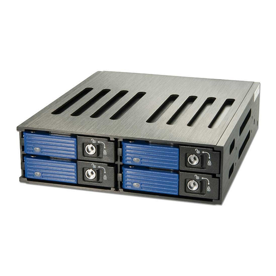
SAS/SATA HDD Backplane Module
User Manual
Benutzerhandbuch
Manuel Utilisateur
Manuale
Hersteller / Manufacturers (EU):
LINDY-Elektronik GmbH
LINDY Electronics Ltd
Markircher Str. 20
Sadler Foster Way
68229 Mannheim
Stockton-on-Tees, TS17 9JY
Germany
United Kingdom
T: +49 (0)621 470050
T: +44 (0) 1642 754000
info@lindy.de
postmaster@lindy.co.uk
LINDY No. 21981
For Home and Office Use
www.lindy.com
Tested to Comply with FCC Standards
© LINDY -
SECOND EDITION - AUGUST 2016
English Manual
The SAS/SATA II HDD Backplane Module is
designed to hold 4 SAS or SATA 2.5" HDDs, each in
an individual tray, and can be installed easily into one
standard 5.25" bay. When SAS HDDs are used two
SATA data connections per HDD (primary and
secondary channel) are supported. When SATA
HDDs are used the secondary SATA ports (yellow)
English
have no function.
Deutsch
Français
To release a HDD tray, slide the bar switch away from
Italiano
the coloured handle and pull it out by the door handle.
To mount or release the HDD, hold the tray with both
hands and carefully push the latch on the top back as
shown by the arrow on top.
Please mount your HDDs in the trays using 4 of the
supplied screws for each HDD. For HDDs with
9.5mm height, put the plastic top cover back into
position while carefully adjusting the front latches into
position on the tray bezel. For HDDs with 12.5mm
height, the top cover must not be used. Now slide the
tray into the bay module by pushing on the black part
of the bezel. When it has reached the back, push the
coloured handle until it snaps into position so that the
tray does not stand out from the 5.25" frame.
The DIP switch on the back of the module selects
LED(?) and staggered spin up function:
o position: LED flashing flickering blue for access
and staggered spin up enabled
x position: LED non-flashing flickering and spin up
with power enabled
Deutsches Benutzerhandbuch
Dies Backplanemodul wurde entwickelt um vier
SAS oder SATA HDDs auf individuellen Einschü-
ben in nur einem einzigen 5,25" Standard-
Einbauschacht unterzubringen. Bei Verwendung
von SAS-Festplatten werden zwei SATA
Datenanschlüsse pro Platte unterstützt. Bei
Verwendung von SATA Festplatten sind die
sekundären gelben SATA Anschlüsse ohne
Funktion.
Um einen Plattenträger herauszunehmen schieben
Sie die Taste vom farbigen Hebel weg und ziehen
Sie den Einschub am aufspringenden Hebel
heraus. Nehmen Sie den Einschub in beide Hände
und drücken Sie die Lasche hinten oben vorsichtig
in Pfeilrichtung um den Kunststoffdeckel
abzunehmen.
Schrauben Sie die Festplatte auf dem Träger fest
und befestigen Sie den Kunststoffdeckel wieder.
Achten Sie dabei darauf, die Laschen an der
Vorderseite korrekt in die Frontblende zu
positionieren und rasten Sie die hintere Lasche
ein. Durch Drücken auf den schwarzen Teil der
Blende schieben Sie den Rahmen bis ganz nach
hinten ein. Leichter Druck auf den farbigen
Verriegelungshebel lässt diesen dann hör- und
fühlbar einrasten, so dass der Einbaurahmen nicht
aus dem 5,25" Rahmen hervorsteht.
Der DIP Switch an der Rückseite legt die
Funktion für LED und Anlaufverzögerung fest:
o-Position: LED blinkt bei Zugriffen,
Anlaufverzögerung aktiv
x-Position:
LED
blinkt
Anlaufverzögerung, Platten laufen gleich hoch
nicht,
keine

Verwandte Anleitungen für Lindy 21981


Inhaltszusammenfassung für Lindy 21981
- Seite 1 Funktion für LED und Anlaufverzögerung fest: x position: LED non-flashing flickering and spin up with power enabled o-Position: LED blinkt bei Zugriffen, Anlaufverzögerung aktiv LINDY No. 21981 x-Position: blinkt nicht, keine Anlaufverzögerung, Platten laufen gleich hoch For Home and Office Use www.lindy.com...
- Seite 2 Ausführliche Informationen zu diesen Themen finden Sie stets aktuell auf der LINDY Webseite im placez le capot avec précaution après avoir ajusté Fußbereich. Tramite i DIP switch sul retro del modulo potete la position du levier de sécurité.