Herunterladen Inhalt Inhalt Diese Seite drucken

Werbung

Verfügbare Sprachen

Verfügbare Sprachen

USER MANUAL
MANUAL DE INSTRUCCIONES
NOTICE D'UTILISATION
BEDIENUNGSANLEITUNG

Werbung

Inhaltsverzeichnis
loading

Inhaltszusammenfassung für Ecler verso SB115P

  • Seite 1 USER MANUAL MANUAL DE INSTRUCCIONES NOTICE D'UTILISATION BEDIENUNGSANLEITUNG...
  • Seite 3: Inhaltsverzeichnis

    6. OTHER CONSIDERATIONS 7. FUNCTION LIST 8. FUNCTION DIAGRAM 9. TECHNICAL CHARACTERISTICS 10. BLOCK DIAGRAM All numbers subject to variation due to production tolerances. ECLER, S.A. reserves the right to make changes or improvements in manufacturing or design which may affect specifications.
  • Seite 4: Important Remark

    In some of these applications you need an element which strengthens the lower end of the audible spectrum, i.e. the lower frequencies or sub-bass. The VERSO SB115P self-powered subwoofer is ideal for this task.
  • Seite 5: Use

    R. Feed them a mono or stereo line level signal: the SB115P processes mono signals and therefore sums L and R input signals to work on a valid signal. You can link a second VERSO SB115P or other auxiliary equipment using L and R STACK outputs, also available on XLR connectors. The L and R STACK output signal is a copy of the signal received at L and R INPUT.
  • Seite 6: Placement And Installation

    5. PLACEMENT AND INSTALLATION Please observe the following general rules: As a subwoofer, the VERSO SB115P has been designed to be installed in discrete places. Low frequencies are considered to be non-directional so the VERSO SB115P can be perfectly placed in corners, under a table, behind curtains... that will not notably affect its output. Generally, it should be known that placing it close to various surfaces will increase its efficiency.
  • Seite 7: Other Considerations

    Audio connections: As a general rule, try to ensure that the signal connections are as short as possible and use the best quality connectors and cables. Poor quality of the connections and/or cable used could lead to an important deterioration of the sound reproduction quality. The Ecler catalogue contains the necessary cabling references.
  • Seite 8: Function List

    7. FUNCTION LIST 8. FUNCTION DIAGRAM 1. Low-pass filter switch, LPF 2. Phase inverter switch, PHASE 3. Signal present indicator, SP 4. Input attenuator, VOL 5. Clip indicator, CLIP 6. Input XLR connector, INPUT 7. XLR output connector to other amplifiers, STACK 8.
  • Seite 9 9. CARACTERÍSTICAS TÉCNICAS 10. DIAGRAMA DE BLOQUES Todos los datos están sujetos a variación debida a tolerancias de producción. ECLER S.A. se reserva el derecho de realizar cambios o mejoras en la fabricación o diseño que pudieran afectar las especificaciones.
  • Seite 10: Nota Importante

    En algunas de estas aplicaciones es preciso contar también con un elemento de refuerzo de la franja inferior del espectro audible, es decir, de las frecuencias más bajas o subgraves. El VERSO SB115P es un altavoz subgrave autoamplificado ideal para tal cometido.
  • Seite 11: Utilización

    L y R para obtener una señal válida de trabajo. Es posible enlazar una segunda unidad VERSO SB115P u otro equipo auxiliar mediante el uso de la salida STACK L y R, disponible también con conectores tipo XLR. La señal de salida STACK L y R es una réplica de la señal conectada a las entradas INPUT L y R.
  • Seite 12: Ubicación Y Montaje

    5. UBICACIÓN Y MONTAJE Como reglas generales se observarán las siguientes: Como subwoofer la unidad VERSO SB115P, está diseñada para ser ubicada en lugares discretos. Dada la naturaleza omnidireccional de las bajas frecuencias, puede ser perfectamente ubicada en rincones, debajo de mesas, detrás de cortinas ... ello no afectará notablemente a su rendimiento.
  • Seite 13: Otras Consideraciones

    En el catálogo de Ecler hallará las referencias de cableado necesarias. Ruido de fondo: el empleo de circuitería activa puede aportar, según configuración, un nivel de ruido de fondo más o menos elevado.
  • Seite 14: Lista De Funciones

    7. LISTA DE FUNCIONES 8. DIAGRAMA DE FUNCIONES 1. Conmutador filtro pasa bajos, LPF 2. Conmutador inversor de fase, PHASE 3. Indicador luminoso de presencia de señal, 4. Atenuador de entrada, VOL 5. Indicador luminoso de recorte, CLIP 6. Conector XLR de entrada, INPUT 7.
  • Seite 15 10. DIAGRAMME DE BLOCS Le contenu de ce manuel peut être amené à changer, du fait de tolérances de production. La société ECLER S.A. se réserve le droit d'apporter des modifications ou des améliorations à la fabrication ou à la conception du produit,...
  • Seite 16: Note Importante

    Dans certaines de ces applications il est nécessaire de disposer aussi d’un renfort de la bande inférieure du spectre audible, c'est-à-dire des fréquences plus basses ou infra-graves. Le VERSO SB115P est un caisson d’infra-graves autoamplifié idéal pour cela.
  • Seite 17: Utilisation

    L et R pour obtenir un signal de travail adéquat. Il est possible d’enchaîner un second VERSO SB115P ou un autre équipement auxiliaire grâce à la sortie de renvoi STACK L et R, disponible aussi sur connecteurs XLR. Le signal de sortie STACK L et R est une reproduction du signal reçu aux entrées INPUT L et R.
  • Seite 18: Positionnement Et Montage

    5. POSITIONNEMENT ET MONTAGE Respectez les règles générales suivantes: En tant que caisson de graves, la VERSO SB115P est conçu pour être placé en des lieux discrets. Vu la nature omnidirectionnelle des basses fréquences, la VERSO SB115P peut parfaitement être placé dans des coins, sous des tables, derrière des rideaux... cela n'affectera pas notablement son rendement.
  • Seite 19: Autres Considérations

    Une mauvaise qualité des connexions et/ou du câble utilisé peuvent occasionner des détériorations lors de la lecture. Dans le catalogue d’Ecler vous trouverez les références de câblage nécessaires.
  • Seite 20: Liste De Fonctions

    7. LISTE DE FONCTIONS 8. SCHEMA DE FONCTIONS 1. Commutateur de filtre passe-bas, LPF 2. Commutateur d'inversion de phase, PHASE 3. Indicateur de présence du signal, SP 4. Atténuateur d'entrée, VOL 5. Voyant d'écrêtage, CLIP 6. Connecteur XLR en entrée, INPUT 7.
  • Seite 21 7. FUNKTIONSLISTE 8. FUNKTIONSDIAGRAMM 9. TECHNISCHE DATEN 10. BLOCKSCHATBILD Alle angegebenen Werte unterliegen gewissen Schwankungen infolge Produktionstoleranzen. ECLER S.A. behält sich das Recht zu Änderungen oder Weiterentwicklungen in Produktion oder Design vor, die Abweichungen der technischen Daten zur Folge haben können.
  • Seite 22: Wichtiger Hinweis

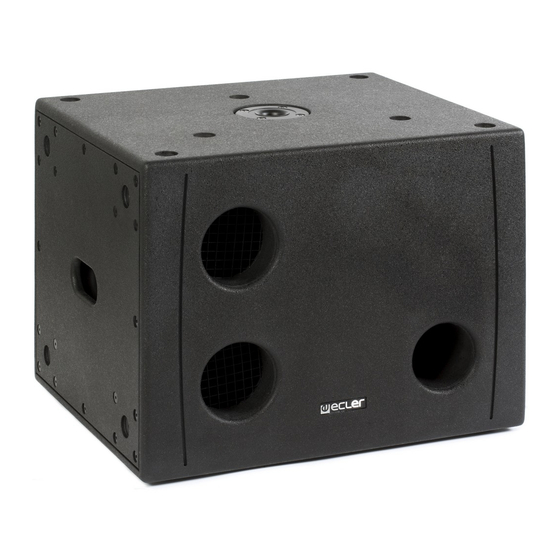
    Bei einigen dieser Anwendungen ist es notwendig, auch über ein Verstärkungselement für den unteren Bereich des hörbaren Spektrums zu verfügen, d.h., für die tieferen Frequenzen oder Subwoofer. Der VERSO SB115P ist ein aktiver Subwoofer, der für diesen Zweck bestens geeignet ist.
  • Seite 23: Verwendung

    L-/R-Eingangssignale, um ein gültiges Arbeitssignal zu erhalten. Mit Hilfe des Ausgangs STACK L und R, ebenfalls verfügbar mit XLR-Anschlüssen, ist es möglich, ein zweites VERSO SB115P-Gerät oder ein sonstiges Hilfsgerät anzuschliessen. Die Signale am Ausgang STACK L und R sind eine exacte Kopie der an den Eingängen INPUT L und R anliegenden Signale.
  • Seite 24: Aufstellungsort Und Montage

    CLIP: LED-Anzeige, die aufleuchtet, sobald das am Eingang anliegende Signal so stark ist, dass es zu einer Übersteuerung des internen Verstärkers kommen kann. 5. AUFSTELLUNGSORT UND MONTAGE Beachten Sie folgende Empfehlungen: Der VERSO SB115P ist als Subwoofer so entworfen, daß sie problemlos in einer diskreten Plazierung aufgestellt werden kann.
  • Seite 25: Sonstige Betrachtungen

    Stecker von bester Qualität verwendet werden. Durch eine schlechte Qualität der eingesetzten Anschlüsse bzw. Kabel kann die Wiedergabequalität stark beeinträchtigt werden. Im Produktkatalog von Ecler finden Sie die Referenzen für die erforderlichen Kabel. Grundgeräusch: Der Einsatz von aktiven Schaltungen kann je nach Einstellung zu einem mehr oder weniger starken Grundgeräuschpegel führen.
  • Seite 26: Funktionsliste

    7. FUNKTIONSLISTE 8. FUNKTIONSDIAGRAMM 1. Umschalter Tiefpassfilter, LPF 2. Phasenumkehrschalter PHASE 3. Signalanzeige, SP 4. Eingangsregler, VOL 5. Clip Anzeige, CLIP 6. XLR Eingangsbuchse, INPUT 7. XLR Ausgangsbuchse zu anderen Verstärkern, STACK 8. Spannungswechsel 9. Hauptschalter, O/I 10. Sicherungskapsel 11. Stromanschluss...
  • Seite 27: Technical Characteristics

    9. TECHNICAL CHARACTERISTICS 9. CARACTERÍSTICAS TÉCNICAS 9. CARACTÉRISTIQUES TECHNIQUES 9. TECHNISCHE DATEN System Bass active cabinet Driver 15"x1 Power output (RMS) 500W Maximum SPL (dB@1m) 125dB Inputs sensitivity nom/impedance 0dBV 1V 20kΩ (Balanced) Input connector type XLR3 balanced Stack connector type XLR3 balanced Frequency response (-3dB) 35Hz~100Hz / 35Hz~150Hz...
  • Seite 28 ECLER Laboratorio de electro-acústica S.A. Motors 166-168, 08038 Barcelona, Spain INTERNET http://www.ecler.com e-mail: info@ecler.es 50.0213.01.00...

Inhaltsverzeichnis