Inhaltsverzeichnis
Werbung
Verfügbare Sprachen
Verfügbare Sprachen
Quicklinks
Werbung
Kapitel
Inhaltsverzeichnis

Verwandte Anleitungen für Ten-Haaft SunMover

Inhaltszusammenfassung für Ten-Haaft SunMover
- Seite 1 Montageanleitung Installation Instructions / Manuel de montage mit externem Laderegeler with external charge controller avec régulateur de charge externe Innovative Mobile Technology 07/2010 Sprache / language / langue: deutsch / english / français...
- Seite 2 Inhaltsverzeichnis / Table of content / Manuel d’utilisation Deutsch English Français...
- Seite 3 Deutsch...
-
Seite 4: Inhaltsverzeichnis
Inhaltsverzeichnis Bestimmungsgemäße Verwendung Lieferumfang Montagevorarbeiten Schritt 1: Montageplatte montieren Schritt 2: System aufsetzen Schritt 3: Konfi guration des Ladereglers Solara SR 135 Schritt 4: Spannungsversorgung Schritt 5: Die erste Inbetriebnahme Schritt 6 : Montage des Solarpanels Schritt 7: Kalibration Fehlermeldungen und Fehlerdiagnose Demontage der Anlage Hinweise zum Umweltschutz Schablonen... -
Seite 5: Bestimmungsgemäße Verwendung
Bestimmungsgemäße Verwendung Die bestimmungsgemäße Verwendung dieses Produktes ist die Festmontage auf Wohnmobilen oder Wohnanhängern (Caravans) mit einer Höchstgeschwindigkeit von nicht mehr als 130 km/h. Die Anlage dient zum Zwecke des Aufl adens der im Fahrzeug eingebauten, wiederaufl adbaren Batterien (Akkumulatoren). Hierbei muss es sich um handelsübliche Akkumulatoren mit einer Nennspannung von 12V (6 Zellen) und einer Nennkapazität von mindestens 50Ah handeln. -
Seite 6: Lieferumfang
Lieferumfang Das sollte jetzt vor Ihnen liegen: Bedienteil Außeneinheit mit Montageplatte Solarmodul Schraubenpackung Kabelsatz zur Außeneinheit Bedienungsanleitung Montageanleitung Laderegler Entsorgungshinweis für Verpackungen Verpackungen und Packhilfsmittel sind recyclingfähig und müssen grund-sätzlich der stoffl ichen Wiederverwertung zugeführt werden. Verpackungsmaterialien wie z.B. Folienbeutel gehören nicht in Kinderhände. -
Seite 7: Montagevorarbeiten
Montagevorarbeiten 1. Vorbereitung Bevor Sie die Montage beginnen, achten Sie bitte darauf, dass das Dach Ihres Fahr- zeugs ausreichend stabil ist. Weiterhin sollten Sie die bei der Montage und beim Besteigen des Daches die zulässige Dachlast Ihres Wohnmobils nicht überschreiten. Bei ungenügender oder zweifelhafter Dachstabilität für die Anlage kann ein ca. - Seite 8 Radius 77cm ab Höhe 12cm Radius 22cm ab Höhe 12cm 98cm 3. Montageort Richtig aufgesetzt muss jetzt das Steckergehäuse der Außeneinheit mit dem An- schlusskabel in Richtung Fahrzeugheck zeigen, andere Positionen sind nicht zulässig - siehe Zeichnung unten. Für die endgültige Wahl des Montageplatzes beachten Sie unbedingt den erforder- lichen Platzbedarf auf dem Fahrzeugdach und berücksichtigen Sie zur Erleichterung der späteren Kabelverlegung die Position der Aufbau Batterie sowie die Standort- wahl des Bedienteils.
-
Seite 9: Schritt 1: Montageplatte Montieren
Schritt 1: Montageplatte montieren Nachdem nun der endgültige Montageplatz der Anlage feststeht und Sie sich nochmals von der korrekten Lage in Bezug auf die Fahrtrichtung überzeugt haben (Kabelauslass der Anlage zeigt in Richtung Fahrzeugheck), markieren Sie die Eck- punkte der Montageplatte. Nehmen Sie das System jetzt nach Lösen der vier Befestigungsmuttern durch Anhe- ben von der Montageplatte ab. -
Seite 10: Schritt 2: System Aufsetzen
Schritt 2: System aufsetzen Setzen Sie die Außeneinheit auf die Montageplatte so auf, dass das Steckergehäuse und der Kabelauslass der Außeneinheit zum Fahrzeugheck zeigen. Jede andere Posi- tion der Anlage ist nicht zulässig und führt zum Erlöschen der Gewährleistung. Wurde die Montageplatte vorher richtig montiert, so zeigen das LNB und der Kabel- auslass jetzt in Richtung Fahrzeugheck. -
Seite 11: Abdichtung Der Dachdurchführung
b) Verlegen Sie das Kabel ordentlich auf dem Fahrzeugdach z.B. in einem Kabelkanal und führen dann das aus der Winkelverschraubung kommende Kabel nach unten zum Bedienteil. c) Die kleine Montageplatte für die Winkelverschraubung wird auf dem Fahrzeugdach mit handelsüblicher Karosserieklebedichtmasse verklebt und anschließend verschraubt. -
Seite 12: Schritt 3: Konfi Guration Des Ladereglers Solara Sr 135
Schritt 3: Konfiguration des Ladereglers Solara SR 135 Zum Konfi gurieren muss der Laderegler geöffnet werden. Entfernen Sie dazu die Kreuzschlitzschraube auf der Rückseite des Ladereglers und nehmen den Gehäuse- deckel ab. Sie sehen die interne Elektronik sowie 3 Steckbrücken (Jumper) welche richtig gesteckt werden müssen. - Seite 13 Beispiel: Wir haben eine Gel Batterie im Fahrzeug. Der Tiefentladeschutz überwacht die Batteriespannung. Es soll im Fall einer Tiefentladung kein Warnsignal ertönen: Brücke 1: Geschlossen Brücke 2: Geschlossen Brücke 3: Offen (Eine detaillierte Beschreibung des Solara SR 135 Ladereglers fi nden Sie auf dem Beiblatt in dessen Verpackung) Den Laderegler mit 2 Schrauben vorzugsweise in Batterienähe montieren.
-
Seite 14: Schritt 4: Spannungsversorgung
Schritt 4: Spannungsversorgung Ihr SunMover® wurde mit einem perfekt auf die Anwendung zugeschnittenen Kabelsatz ausgeliefert. Verwenden Sie zum elektrischen Anschluss der Anlage an Ihr Fahrzeug-Bordnetz ausschließlich diesen Kabelsatz. Fahrzeugheck Fahrtrichtung Außeneinheit Winkelverschraubung Steckergehäuse Montageplatte Länge 4m ab Außeneinheit bis Abzweigung Sicherungshalter Länge 90cm ab Abzweigung... - Seite 15 Als nächstes müssen Sie die Batterie Anschluss-/Ladeleitung direkt an die Aufbau-/ Wohnraumbatterie anschließen. Achtung: Schließen Sie das rote und braune Kabel Ihres SunMovers® immer nur direkt an die Batterieklemmen der Aufbau-/Wohnraumbatterie an, niemals hinter irgendwelchen Zusatzgeräten. Schließen Sie Ihren SunMover® auch nie- mals an der Starterbatterie an.
- Seite 16 Sie bitte die Vorschriften des jeweiligen Herstellers. Laderegler / Charge controller Art. No. SR135TL Laden Anschluss des charging Ladereglers Solara SR135: >75% Batteriezustand battery status 25 - 75% <25% Lastzustand load status SOLARA Gelbes Kabel Minuspol (Masse) SunMover® Bordbatterie Schwarzes Kabel Pluspol SunMover® Bordbatterie...
-
Seite 17: Schritt 5: Die Erste Inbetriebnahme
Schritt 5: Die erste Inbetriebnahme Wenn alle Montage- und Anschlussarbeiten – außer der Montage des Solarpanels – soweit abgeschlossen sind, kann die Anlage zum ersten Mal eingeschaltet werden. Sollte der Microprozessor beim Anschluss des SunMovers® an die Batterie wäh- rend des automatischen Selbsttests einen Fehler erkannt haben, wird dieser in der Anzeige des Bedienteiles eingeblendet. -
Seite 18: Schritt 6 : Montage Des Solarpanels
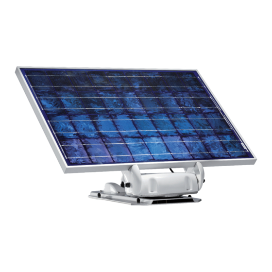
Schritt 6 : Montage des Solarpanels Das Solarpanel wird auf die zwei weißen Arme gelegt und mit beiliegenden 6 Stück M8 Schrauben und den Federringen verschraubt. Da die Schrauben unterschiedlich lang sind, achten Sie bitte auf die entsprechende Zuordnung. Die längste Schraube ist unten, die kürzeste oben. -
Seite 19: Schritt 7: Kalibration
Schritt 7: Kalibration Um das Solarmodul jederzeit korrekt auf die Sonne ausrichten zu können, verwendet Ihr SunMover® unter anderem einen elektronischen Kompasssensor. Dieser Sensor wurde im Werk vorkalibriert (eingestellt), so dass die Anlage in der Regel problemlos funktionieren wird. Allerdings haben Kraftfahrzeuge häufi g einen gewissen Ein- fl... - Seite 20 CALIBRATION OK In der Anzeige sollte jetzt zu sehen sein. In diesem Fall ist alles in Ordnung und Ihr SunMover® hat sich an die Gegebenheiten Ihres Fahrzeuges angepasst. CAL ERROR Sollten Sie eventuell die Meldung auf der Anzeige des Be- dienteiles sehen, so müssen den Vorgang wiederholen, da der Mikroprozessor die...
-
Seite 21: Fehlermeldungen Und Fehlerdiagnose
Fehlermeldungen und Fehlerdiagnose Direkt nach dem Anlegen der Versorgungsspannung führt die Anlage einen Selbst- test durch. Hierbei werden die diversen internen Funktionen überprüft. Sollten hierbei Fehlermeldungen auftreten, fi nden Sie in der folgenden Tabelle die möglichen Ursachen: Anzeige Ursache Die Anlage ist nur zum Betrieb an 12V Bordspannungsnetzen vorgesehen. Eventuell liegt auch eine defekte Batterie oder ein Verkabelungsproblem Power failure vor. -
Seite 22: Demontage Der Anlage
Demontage der Anlage Für die Demontage der Außeneinheit benötigen Sie zusätzlich einen Gabelschlüssel SW 10. Es ist nicht notwendig die Zuleitung zu demontieren. Gehen Sie wie folgt vor: Lösen Sie die vier Muttern M8, welche die Grundplatte mit der Montageplatte verbinden. -
Seite 23: Hinweise Zum Umweltschutz
Die Entsorgung kann demgemäß im Rahmen der Altfahrzeug-Verord- nung (Europäische Altfahrzeugrichtlinie ELV, 2000/ 53/EG; für Deutschland: Altfahr- zeugV) zusammen mit dem Kraftfahrzeug erfolgen. Der Receiver enthält keine der gemäß Richtlinie als umweltschädlich eingestuften Stoffe. Abschließend wünschen wir Ihnen viel Freude mit Ihrem neuen ten Haaft Produkt! - Seite 24 English...
- Seite 25 Table of contents Proper use and operation Scope of supply Installation preparation Step 1: Installing the mounting plate Step 2: Locating the external unit Step 3: Confi guration of Solara SR 135 charge controller Step 4: Power supply Step 5: Initial operation Step 6: Installation of the solar panel Step 7: Calibration Fault messages and fault diagnosis...
-
Seite 26: Proper Use And Operation
Proper use and operation This product has been designed for use in a fi xed installation on mobile homes or camper trailers with maximum speeds of 130 km/h. The system is intended for the purpose of charging the rechargeable battery/batteries installed in the vehicle. The- se batteries must be standard commercially available batteries with a voltage rating of 12 V (6 cells) and a rated capacity of at least 50 Ah. -
Seite 27: Scope Of Supply
Scope of supply Your system is supplied with the following items: Control panel External unit with mounting plate Solar module Fastener package Wiring harness to external unit Operating Instructions Installation instructions Charge controller Information about disposal of packaging Packaging and packaging materials can be recycled. Please observe the applicable legislation in your country governing recycling and your duty to dispose of recyclab- le waste in the proper way. -
Seite 28: Installation Preparation
Installation preparation 1. Preparation Before starting the installation, ensure that the roof of your vehicle is suffi ciently sturdy. Ensure that the permissible roof load of your vehicle is not exceeded when installing the system and accessing the roof. If the roof is not strong enough, or if you are in any doubt, attach a sheet-metal panel (approx. - Seite 29 Radius 77cm at hight 12cm Radius 22cm at hight 12cm 78cm 3. Installation position When positioned correctly, the connector housing of the external unit and the connecting cable should point towards the rear of the vehicle. Any other position is incorrect –...
-
Seite 30: Step 1: Installing The Mounting Plate
Step 1: Installing the mounting plate Once you have determined the fi nal installation position of the system and you have checked again that it is correctly positioned in relation to the driving direction (cable outlet pointing towards the rear of the vehicle), mark the corner points of the mounting plate. -
Seite 31: Step 2: Locating The External Unit
Step 2: Locating the external unit Place the external unit on the mounting plate with the connector housing and the cable outlet of the external unit facing towards the rear of the vehicle. An ins- tallation in any other position is not permitted and will cause the warranty to be invalidated. - Seite 32 b) Route the cable tidily on the roof of the vehicle (e.g. using a cable duct) and guide the cable coming out of the threaded elbow fi tting downwards to the control panel. c) The small mounting plate of the threaded elbow fi tting is bonded to the roof of the vehicle using commercially available body sealing compound and is then secured to the roof with screws.
-
Seite 33: Step 3: Confi Guration Of Solara Sr 135 Charge Controller
Step 3: Configuration of charge controller Solara SR 135 The charge controller must be opened for the confi guration. Remove the Philips screw on the back of the charge controller and remove the cover. The integrated electronics and 3 jumper contacts that need to be correctly connected are now visible. - Seite 34 Example: The vehicle is equipped with a lead-gel battery. The battery‘s voltage is monitored by the total-discharge protection function. If no signal shall sound in the event of a total discharge: Brücke 1: closed Brücke 2: closed Brücke 3: Open (Please see the product information sheet in the package of the Solara SR 135 charge controller for more details.) Install the charge controller near the battery, if possible, using the two screws.
-
Seite 35: Step 4: Power Supply
Step 4: Power supply Your SunMover® is supplied with a perfectly matched cable harness. Do not use any other wiring except this cable harness to connect the system to the electric system of your vehicle. Rear of the vehicle Driving direction... - Seite 36 This cable controls some important functions of your SunMover®, hence the correct connection of this cable must be ensured. You can either route this cable in the interior, for example to an existing entry-step control system or to a refrigerator with a corresponding changeover contact, and connect it there.
- Seite 37 Laderegler / Charge controller Art. No. SR135TL Laden Connection of charging charge controller Solara SR135: >75% Batteriezustand battery status 25 - 75% <25% Lastzustand load status SOLARA yellow cable Negative terminal (ground) SunMover® Onboard battery black cable Positive terminal SunMover® Onboard battery...
-
Seite 38: Step 5: Initial Operation
If the microprocessor discovered a fault during the automatic self-test after con- nection of the SunMover® to the battery, this will be shown on the display of the control panel. If no fault was discovered then the system will have switched off again automatically. -
Seite 39: Step 6: Installation Of The Solar Panel
Step 6 : Installation of the solar panel Place the solar panel onto the two white arms and secure it with the 6 enclosed M8 bolts and lock washers. As the bolts have different lengths, please make sure that the longest bolt is at the bottom and the shortest is at the top. Afterwards, open the black housing on the rear of the solar panel using a narrow fl... -
Seite 40: Step 7: Calibration
Step 7: Calibration Your SunMover® also uses an electronic compass sensor to keep the solar module correctly aligned towards the sun at all times. This sensor has been calibrated at the factory, so the system should work without problems in most cases. However, motor vehicles often exert a certain infl... - Seite 41 CALIBRATION OK The display should now show the message . In this case, everything is in order and your SunMover® has adapted itself to the conditions in your vehicle. CAL ERROR If the message is displayed in control panel, repeat the pro- cedure as the microprocessor was not able to obtain the required data.
-
Seite 42: Fault Messages And Fault Diagnosis
Fault messages and fault diagnosis After connection of the supply voltage the system performs a self-test. This test checks the various internal system functions. Should any fault messages be displayed, please refer to table below: Message Cause The system is designed for operation with a 12V onboard power supply only. -
Seite 43: Removal Of The System
Removal of the system The removal of the exterior unit requires a 10-mm open-end spanner. The supply line does not need to be removed. Proceed as follows: Undo the four M8 nuts securing the base plate to the mounting plate. Lift off the system. -
Seite 44: Notes On The Protection Of The Environment
End- of-Life Vehicle Directive ELV, 2000/53/EC. The receiver does not contain any materi- als rated as hazardous to the environment according to the directive. We hope you get a lot of enjoyment out of your new ten Haaft product! - Seite 45 Français...
- Seite 46 Table des matières Utilisation conforme à la destination Volume de la livraison Préparation du montage Pas 1 : Monter la plaque de fi xation Pas 2 : Mise en place du système Pas 3 : Confi guration de régulateur charge Solara SR 135 Pas 4 : Alimentation électrique Pas 5 : Première mise en service Pas 6 : Montage du panneau solaire...
-
Seite 47: Utilisation Conforme À La Destination
Utilisation conforme à la destination L’utilisation conforme à la destination de ce produit est un montage fi xe sur un camping car ou une caravane dont la vitesse ne doit pas dépasser 130 km/h en vue de charger les batteries (accumulateurs rechargeables) montées dans le véhicule. Il doit s’agir d’accumulateurs au plomb ou au gel de plomb du commerce d‘une tensi- on nominale de 12 V (6 éléments) et d’une capacité... -
Seite 48: Volume De La Livraison
Volume de la livraison Ce que vous devriez avoir devant vous : Boîtier de commande Unité extérieure avec module solaire prémonté et antenne parabolique Plaque de fi xation Jeu de vis Faisceau de câblage allant à l’unité extérieure Instructions d’utilisation Instructions de montage Régulateur de charge Instructions concernant l’élimination des emballages:... -
Seite 49: Préparation Du Montage
fi xation et d’un adhésif d’étanchéité de carrosserie à fort pouvoir adhésif (ex : Sikafl ex). 2. Encombrement de la SunMover® Il est important qu´il y ait assez de place lorsque l´antenne est refermée, mais aussi pour le rayon de rotation. - Seite 50 Rayon 77cm jusqu´ à 12cm Rayon 22cm de hauteur jusqu´ à 12cm de hauteur 98cm 3. Choix de l´emplacement du montage Si le montage est correct, le bras de l´antenne et la sortie de câblage doivent être orientés vers l´arrière du véhicule, une autre position n´est pas autorisée. (voir dessin ci-dessus) Pour le choix d´fi...
-
Seite 51: Pas 1 : Monter La Plaque De Fi Xation
Pas 1 : Monter la plaque de fixation Une fois que vous avez défi ni l´emplacement défi nitif du système et que vous avez vérifi é que l´emplacement était correct par rapport au sens de déplacement du véhi- cule (sortie de câblage du système orientée vers l´arrière du véhicule) repérez les angles de la plaque de fi... -
Seite 52: Pas 2 : Mise En Place Du Système
Pas 2 : Mise en place du système Positionner l’unité extérieure sur la plaque de fi xation de telle sorte que le boîtier de connecteurs et la sortie de câblage de l‘unité extérieure soient orientés vers l‘arrière du véhicule. Toute autre position du système est interdite et entraîne l’annulation de la garantie. - Seite 53 b) Posez proprement le câble sur le toit du véhicule (dans un conduit de câbles par exemple) et faites passer le câble sortant du raccordement coudé vers le bas jusqu’au boîtier de commande. c) La petite plaque de fi xation pour le raccordement coudé doit être collée sur le toit du véhicule avec de l’adhésif d’étanchéité...
-
Seite 54: Pas 3 : Confi Guration De Régulateur Charge Solara Sr 135
Pas 3 : Configuration de régulateur charge Solara SR 135 Pour pouvoir le confi gurer, ce régulateur doit être ouvert. Il faut dévisser les vis cruciformes de derrière et retirer le couvercle. Vous pourrez voir toute l´electronique à l´intérieur et 3 ponts enfi chables (Jumper) qui devont être branchés correctement. Jumper (pont) 1(gel/liquide) 2 (protecteurs de déchargement) 3 alarme Ouvert... - Seite 55 Exemple: Nous avons une batterie gel dans le véhicule. Le protecteur de décharge surveille la tension de la batterie. On ne devra pas entendre de signal en cas de déchargement : Pont 1: fermé Pont 2: fermé Pont 3: ouvert (une description détaillée du régulateur Solara SR 135 se trouve en supplément de son emballage) Fixer le régulateur avec deux vis et de préférence à...
-
Seite 56: Pas 4 : Alimentation Électrique
Pas 3 : Alimentation électrique Votre SunMover® a été fourni en tant que système complet avec un régulateur de charge intégré et un faisceau de câblage parfaitement adapté à son utilisation. Utilisez exclusivement ce faisceau de câblage pour le raccordement du système au réseau de bord de votre véhicule. - Seite 57 15 ou D+ du réseau de bord. Ces lignes sont sous tension lorsque le contact est établi et hors tension lorsqu’il est coupé. Ce fi l commande quelques fonctions importantes de votre SunMover®, veillez à ce qu’il soit correc- tement raccordé. Vous pouvez connecter ce câble dans l‘habitacle à une commande de marchepieds existante ou à...
- Seite 58 Art. No. SR135TL Laden Prise du régula- charging teur de charge Solara SR135: >75% Batteriezustand battery status 25 - 75% <25% Lastzustand load status SOLARA Câble jaune Pôle negatif( terre) SunMover® Batterie de bord Câble noir Pôle positif SunMover® Batterie de bord...
-
Seite 59: Pas 5 : Première Mise En Service
être mis pour la première fois sous tension. Si, après le raccordement du SunMover à la batterie, le microprocesseur détecte une anomalie lors de l’autodiagnostic automatique, celle-ci est signalée sur l’écran du boîtier de commande. Si aucune anomalie n’est décelée, le système se met automatiquement hors tension. -
Seite 60: Pas 6 : Montage Du Panneau Solaire
Pas 6 : Montage du panneau solaire Le panneau solaire se pose sur les deux bras blancs à l’aide des 6 vis M8 avec rondelles élastiques bombées fournies. Les vis n’ayant pas toute la même longueur, veillez à utiliser chacune à l’endroit approprié. La vis la plus longue est en bas, la plus courte en haut. -
Seite 61: Pas 7: Calibration
Pas 7: Calibration Pour pouvoir à tout moment orienter correctement le module solaire vers le soleil, votre SamY Solar+ utilise un capteur compas électronique. Ce capteur a été pré étalonné en usine de sorte que, normalement, le système devrait fonctionner sans problème. - Seite 62 Si le message CAL ERROR (Erreur cal) s’affi che sur l’écran du boîtier de commande, vous devez répéter la procédure car le microprocesseur n’a pas pu obtenir les informations nécessaires. Dans la plupart des cas, l’opération réussit au deuxième essai. LIMIT ERROR Si le message (Erreur limite) s’affi...
-
Seite 63: Messages D'erreur Et Diagnostic Des Anomalies
Messages d’erreur et diagnostic des anomalies Immédiatement après la mise sous tension, le système exécute un autodiagnostic, pour vérifi er les différentes fonctions internes. Si des messages d‘erreur apparaissent, trouvez-en les causes possibles en vous reportant au tableau suivant: Message Cause Le système est prévu pour fonctionner avec un réseau de bord 12 V uniquement. -
Seite 64: Démontage Du Système
Démontage du système Pour démonter l’unité extérieure, vous aurez en plus besoin d’une clé à fourche de 10 mm. Il n’est pas nécessaire de démonter la ligne d’alimentation. Procédez comme suit: Desserrez les quatre écrous M8 qui fi xent la plaque de base sur la plaque de fi... -
Seite 65: Consignes Sur La Protection De L´environnement
(directives Européen- nes concernant les vieux véhicules ELV2000/53/EG, pour l´Allemagne: vieux véhicu- les). Le récepteur ne contient aucune substance considérée comme dangereuse pour l´environnement. Pour terminer, nous vous souhaitons un bon divertissement avec votre nouveau produit ten Haaft! - Seite 69 Haaft GmbH Oberer Strietweg 8 75245 Neulingen-Göbrichen GERMANY Telefon + 49 (0) 72 37 / 48 55– 0 Telefax + 49 (0) 72 37 / 48 55– 50 E-Mail: info@ten-haaft.com Öffnungszeiten / hours of opening / temps d‘ouverture : MO –...