SilverStone FT04 Bedienungsanleitung
Inhaltsverzeichnis
Inhaltsverzeichnis

Verwandte Anleitungen für SilverStone FT04


Inhaltszusammenfassung für SilverStone FT04
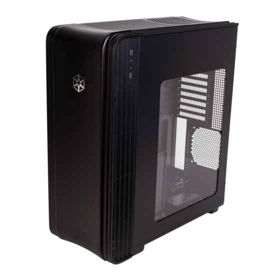
- Seite 1 FORTRESS SERIES FT04 MANUAL...
-
Seite 2: Inhaltsverzeichnis
Installation and system optimization guide: The following manual and guides were carefully prepared by the SilverStone engineering team to help you maximize the potential of your SilverStone product. Please keep this manual for future reference when upgrading or performing maintenance on your system. A copy of this manual can also be downloaded from our website at: http://www.silverstonetek.com... - Seite 3 FT04 FORTRESS SERIES Setting the thermodynamic benchmark Aluminum door and top panel, steel body steel body SSI-EEB, SSI-CEB, Extended ATX, ATX, Micro-ATX Model No. SST-FT04B-W (black + window) SST-FT04S-W (silver + window) 5.25" x 2 Exposed 3.5“ x 1 (transfer bracket,未定案) Internal 3.5"...
- Seite 4 Secure 2.5” HDD Secure optical drives Secure VGA holder and claw Secure PSU, 12025 fan, motherboard and 3.5” HDD Motherboard standoff Secure 12025 fan VGA supporter holder VGA supporter claw Standoff screw Cable management...
-
Seite 6: Installation Guide
lnstallation Guide Loosen two screws from both left Отвинтите по два винта, крепящих and right side panels to remove левую и правую боковых панели, them. и снимите панели. Lösen Sie die beiden Schrauben 取下左右側板各兩顆螺絲,卸下側板。 an den linken und rechten Seitenwänden, nehmen Sie die Seitenwände ab. - Seite 7 lnstallation Guide Loosen three screws holding the Отвинтите три винта, крепящих motherboard tray to remove it. кронштейн материнской платы, и снимите его. Lösen Sie die drei Schrauben, welche 取下主機板托盤3顆螺絲,將主機板托盤抽出。 die Motherboard- Halterung fixieren, nehmen Sie die Halterung ab. Desserrez les trois vis tenant le plateau 取下主机板托盘3颗螺丝,将主机板托盘抽出。...
- Seite 8 lnstallation Guide Remove 3.5” drive cage. Извлеките кронштейн для 3,5-дюймовых жестких дисков. Nehmen Sie die 3,5 移除3.5”主硬碟架。 Zoll-Laufwerkhalterung heraus. Retirez le casier des lecteurs 3.5”. 移除3.5”主硬盘架。 3.5インチドライブケージを取り外します。 Quite la carcasa para dispositivos de 3,5” Rimuovere il supporto hard 3.5” 드라이브 케이지를 제거합니다. drive da 3,5”...
- Seite 9 lnstallation Guide Install 2.5” drive into the bottom of Установите 2,5-дюймовый жесткий диск в the chassis and secure with screws. нижнюю часть корпуса и закрепите его винтами. Installieren Sie das 2,5 Zoll-Laufwerk 將2.5”硬碟裝入機殼底部,並鎖上螺絲。 im unteren Teil des Gehäuses; anschließend mit Schrauben fixieren. Installez le lecteur 2.5”...
- Seite 10 lnstallation Guide Install motherboard rear I/O plate Установите в корпус заднюю панель into the chassis. ввода-вывода материнской платы. Installieren Sie das hintere 將I/O彈片裝上機殼。 I/O-Blech im Gehäuse. Installez la plaque arrière de la carte 将I/O弹片装上机壳。 mère dans le boîtier. Instale la placa trasera de E/S de la ケース内にマザーボード後部...
- Seite 11 lnstallation Guide Reinstall the assembled motherboard Установите кронштейн с материнской tray back into the chassis. If you have платой в сборе в корпус. Если был either the ATX12V 4pin or EPS 8pin подключен 4-контактный разъем кабеля cables connected, please make sure ATX 12 В...
- Seite 12 lnstallation Guide We recommend that you start cable На этом этапе рекомендуется начать manage now and connect cables прокладку кабелей и подсоединить such as the ATX 24pin, front I/O кабели, например кабель ATX с connectors, and any other connectors 24-контактным разъемом, разъемы from front panel devices.
- Seite 13 lnstallation Guide Route all power supply cables to the Проложите все кабели питания через opening on the left of the power отверстие слева от блока питания. supply. Verlegen Sie sämtliche Netzteilkabel 請將所有電源線穿過電源左邊的開孔。 durch die Öffnung links vom Netzteil. Faîtes passer tous les câbles de 请将所有电源线穿过电源左边的开孔。...
- Seite 14 lnstallation Guide Install hard drive cage back into the 1Установите кронштейн для жестких case with cables routed. дисков на место в корпус с проложенными кабелями. Bauen Sie die Laufwerkhalterung 將3.5”主硬碟架裝回機殼, wieder das Gehäuse ein. Achten 同時請注意理線。 Sie darauf, die Kabel sauber zu verlegen.
- Seite 15 lnstallation Guide Connect all cables for 5.25”, 3.5”, Подсоедините все кабели 5,25-дюймовых, and 2.5” drives as needed. 3,5-дюймовых и 2,5-дюймовых устройств соответствующим образом. Schließen Sie sämtliche Kabel für 先連接上所有磁碟需要用到的線材 verwendete 5,25-, 3,5- und (包含5.25”、3.5”以及 2.5”) 2,5-Zoll-Laufwerke an. Branchez tous les câbles pour les 先连接上所有磁盘需要用到的线材...
- Seite 16 lnstallation Guide Insert 3.5” hard drive into the lower Установите 3,5-дюймовый жесткий hard drive cage диск в нижний отсек для жестких дисков Setzen Sie eine 3,5-Zoll-Festplatte 額外的3.5”硬碟,請安裝於底部 in den unteren Festplattenkäfig ein 硬碟架。 Insérez le lecteur 3,5" dans la cage 额外的3.5”硬盘,请安装于底部...
- Seite 17 lnstallation Guide Reinstall both left and right side Для завершения установки установите на panel to complete installation. место левую и правую боковые панели. Installieren Sie zum Abschluss 裝回左右側板,完成組裝。 der Installation die linke und rechte Seitenwand wieder. Réinstallez les deux panneaux latéraux 装回左右侧板,完成组装。...
-
Seite 18: Connector Definition
Connector definition (1) Front panel connector installation Power switch and reset switch installation guide: Please refer to the motherboard manuals for the motherboard’s “Front Panel Connector” or “System Panel Connector” pin definition. Power switch and reset switch have no polarity, so they can be connected in any orientation. Ein-/Ausschalter und Rücksetztaste (Reset) installieren: Bitte suchen Sie in der Motherboard-Dokumentation nach der Pinbelegung der Anschlüsse des Frontbedienfeldes („Front Panel Connectors“... - Seite 19 Connector definition Please refer to the motherboard manuals for the motherboard’s “Front Panel Connector ” or “System Panel Connector” pin definition.; the white/black wires are negative while other colors are positive wires. The Power LED wires are separate pins for compatibility with different motherboard pin definition so please make sure they are connected in the right polarity by referring to your motherboard manual.
-
Seite 20: Front I/O Connector Guide
Front I/O connector guide Below are the front I/O connectors pin definition, please also check your motherboard manual to cross reference with motherboard’s front I/O pin headers. Nachstehend finden Sie die Pinbelegung der vorderen E/A-Anschlüsse; bitte gleichen Sie zudem das Handbuch Ihres Motherboards mit den vorderen E/A-Pinzuweisungen ab. -
Seite 21: Component Size Limitations
Component size limitations The FT04 can accommodate all standard size components and even some that are out of spec, please refer to the following guidelines for component selection and future upgrade considerations: (1) CPU Cooler limitation The height limit is 165mm and there is 13mm of clearance around the motherboard’s top edge. - Seite 22 A: Length limitation The Total length for power supply and optical drive: Power supply and the optical drive space in the FT04 share the same plane so the total limit is 439mm including possible room for cables. We recommend maximum size for power supply of up to 220mm such as the SilverStone’s ST1500. Maximum length limitation for PSU only is 285mm.
- Seite 23 Общая длина блока питания и приводов оптических дисков: Блок питания и привод оптических дисков в корпусе FT04 расположены на одной панели, поэтому их общая длина не может превышать 439 мм, включая возможное пространство для кабелей. Рекомендуется использовать блок питания длиной не более 220 мм, например модель SilverStone ST1500. Ограничение по длине для блока...
- Seite 24 SSI-CEB CPU cooler mounting holes and instead increased the large gap on the motherboard tray to support CPU cooler back plates swapping with more LGA 1156/1155 motherboards. The FT04 chassis’ support for new and future SSI-CEB motherboards should be unaffected by this change.
- Seite 25 Le support du châssis FT04 pour les nouvelles cartes mères SSI-CEB et celles à venir, ne sera pas affecté par cette modification. Note : FT04 a un trou de vis standard pour les cartes mères et n'inclut pas de trou de vis supplémentaire que certains serveurs de carte-mère demandent.
-
Seite 26: Cpu And Graphic Card Supporter
CPU and graphic card supporter A : CPU Cooler Supporter (1) First set the chassis on its side, make sure it is on a level surface. (2) The CPU supporter has already been installed in a commonly used position. You can loosen the screw in the middle to fully extend it. (3) If the supporter position is not optimal for your setup, remove two more screws on left and right side to move the supporter. - Seite 27 A : CPU Cooler Supporter (1) Per prima cosa disporre il cabinet su un fianco, possibilmente su una superficie piana. (2) Il supporto per il dissipatore è già installato nel case in una posizione standard. Potete allentare le viti al centro per estenderlo completamente. (3) Se il supporto non si trova in posizione ottimale per il vostro setup, rimuovere due ulteriori viti a destra ed a sinistra per posizionare il supporto stesso.
-
Seite 28: Optimal Thermal Performance Layout
만약 타워 스타일의 CPU 쿨러를 사용한다면, CPU 팬이 후방으로 향하도록 하여, FT04의 전체적인 공기흐름과 잘 조화되도록 합니다. Optimal Thermal Performance Layout When choosing a graphics card, we recommend models that have fan blowing exhaust air to the rear slot, this will ensure smooth and efficient airflow within the FT04 for maximum cooling performance. - Seite 29 如果您安装高阶显示卡,我们建议您选购风向为朝向Slot端的方式,这样安装上FT04时,风扇才会朝后吹,顺着FT04的气流配置 グラフィックカードを選ぶ際、ファン送風が後部スロット方向に排気を行うモデルを推奨します。これはFT04の中にスムーズで効率的な気流を生じ、 最大の冷却性能を実現します。 그래픽 카드를 선택할때, 슬롯 후면으로 팬의 바람 방향이 슬롯 후면 쪽으로 되어 있는 제품을 선택하기를 바랍니다. 이런 그래픽 카드를 선택해야, FT04의 공기흐름에 맞추어 최대의 냉각 성능을 발휘 할 수 있습니다. Optimal Thermal Performance Layout (3) Tips For Cable Management Please refer to the following diagrams A.
- Seite 30 Optimal Thermal Performance Layout (3) Tips For Cable Management B. The illustration explains which cables the openings are designed for cable placements, the illustration are based on most common motherboard designs. C.There is less than 10mm gap between the front edge of motherboard tray and left side panel. The gap between the top of the 5.25”...
- Seite 31 Guía para el interruptor del ventilador de 180mm: “L” indica estado de baja velocidad y “H” indica estado de alta velocidad La velocità delle ventole Air Penetrator di FT04 può essere regolata tra 600 rpm, 900 rpm e 1200 rpm.Le velocità sono state progettate per un uso in silenziosità o per le prestazioni.
-
Seite 32: Upgrade And Maintenance
étapes vous expliquant comment retirer les filtres des ventilateurs. El diseño de presión de aire positiva de la FT04 es una configuración efectiva que reducirá la acumulación de polvo dentro de la carcasa. Pequeñas partículas de polvo ó pelusa se irán acumularán con el transcurso del tiempo en los filtros de entrada en lugar de en los componentes del interior de la carcasa. - Seite 33 Beim FT04 werden feinere Luftfilter eingesetzt, die einen höheren Luftdurchsatz ermöglichen. Diese weisen ein identisches Filtervermögen auf, jedoch mit einem im Vergleich zu älteren Nylon-Filtern um 65 – 90 % gesteigerten Luftdurchsatz. Allerdings sind diese feineren Filter etwas weniger robust; beachten Sie daher die folgenden Vorsichtsmaßnahmen bei der Reinigung.
- Seite 34 FT04 utilise des filtres à air plus fins qui offrent un taux de débit d’air plus élevé. Ils présentent la même capacité de filtrage mais ont un pourcentage de débit d’air accru de 65% à 90% par rapport à la génération précédente de filtres en nylon. Cependant, ces filtres plus fins ne sont pas aussi durables, veuillez donc prendre note des précautions de nettoyage suivantes lorsque vous les nettoyez.
- Seite 35 イトから検索できます。http://www.silverstonetek.com/wheretobuy_all.php FT04는 공기 흐름 비가 매우 높은 미세한 공기 필터를 사용합니다. 이 필터는 이전 세대의 나일론 필터와 비교할 때 여과 성능은 동일하지만 공기 흐름 비는 65%에서 90%로 증가했습니다. 그러나 미세한 필터는 내구성이 그만큼 좋지 않기 때문에 필터 청소 시 다음과 같은 주의사항에 유의하십시오.
-
Seite 36: Clearcmos
Le FT04 est compatible avec l'installation du SST-CLEARCMOS dans une partie spéciale du boîtier, voici un exemple ci-dessous: La FT04 acepta la instalación de SST-CLEARCMOS en una parte dedicada a ello en la carcasa, por favor vea el ejemplo siguiente: FT04 supporta l’installazione, in una specifica zona del case, di SST-CLEARCMOS, come da esempio seguente:... - Seite 37 E. To reinstall the fan, simply follow the steps in reverse Downgrading to a 120mm fan: A. Secure the fan using normal fan screws onto the transfer bracket that is included in FT04’s accessories box. B. Use the short screw (#6-32) to screw the bracket onto the chassis.
- Seite 38 Downgrading to a 120mm fan: (SG09-P47) 1. Fije el ventilador usando tornillos para ventilador normales en el bracket de transferencia que está incluido en la caja de accesorios de la FT04. 2. Use el tornillo corto (#6-32) para atornillar el bracket al chasis.
-
Seite 39: Protect Your Computer
Kensington Security Slot A lock and cable can be purchased on the market for use with the Kensington security slots located on rear of FT04 to prevent removal of the entire computer or side panels. Caution: Please check for compatibility before purchasing the lock and cable for use with FT04’s Kensington security slots Kensington Security Slot Im Fachhandel erhalten Sie passende Schlösser und Kabel zum Anschluss an den Kensington-Sicherheitsschlitz;... -
Seite 46: Warranty Information
Replacement product will be warranted for remainder of the warranty period or thirty days, whichever is longer. All products should be sent back to the place of purchase if it is within 30 days of purchase, after 30 days, customers need to initiate RMA procedure with SilverStone Technology in USA by first downloading the “USA RMA form for end-users”... - Seite 48 Issue date: January, 2013 G11218050...