Witt HR Montage- Und Betriebsanleitung
Hochdruckschwimmer regler

Verwandte Anleitungen für Witt HR

Inhaltszusammenfassung für Witt HR
- Seite 1 Hochdruckschwimmer- Regler Montage- und Betriebsanleitung High side float regulator Installation- and operating instructions HR/HS...
- Seite 2 HR / HS Montage- und Betriebsanleitung operation and service manual...
-
Seite 3: Inhaltsverzeichnis
HR / HS MONTAGE- UND BETRIEBSANLEITUNG OPERATION & SERVICE MANUAL INHALTSVERZEICHNIS CONTENTS 1. EINLEITUNG................4 1. INTRODUCION .................4 VERWENDUNGSZWECK..........4 INTENDED USE .............4 SICHERHEITSBESTIMMUNGEN ........4 SAFETY REQUIREMENTS..........4 HAFTUNGSAUSSCHLUß ..........4 MANUFACTURER DISCLAIMER........4 2. GEWÄHRLEISTUNGSBESTIMMUNGEN ........ 5 2. TERMS OF WARRENTY............5 3. -
Seite 4: Einleitung
VERWENDUNGSZWECK INTENDED USE Der WITT Hochdruckschwimmer-Regler darf ausschließlich in The WITT high-pressure float regulator is intended for Kälteanlagen eingesetzt werden, um verflüssigtes Kältemittel the use in refrigerant plants to expand liquid refrigerant von der Hochdruckseite auf die Niederdruckseite zu entspan- from the high pressure to the low-pressure side. -
Seite 5: Gewährleistungsbestimmungen
• beim Austausch von Teilen bzw. für die Ersatzteilbeschaf- • Parts that are used during maintenance or service fung nicht die vom Hersteller freigegebenen Originalersatz- are not the approved genuine TH. WITT spare parts. teile verwendet werden. TECHNISCHE INFORMATION TECHNICAL INFORMATION... -
Seite 6: Lieferumfang
Fig.1a HR 1 – 3 Fig. 1b HR 4 LIEFERUMFANG SCOPE OF DELIVERY STANDARD LIEFERUMFANG HR STANDARD SCOPE OF DELIVERY HR Absperrventile am Eintritt- und Austrittsstutzen bzw. Stop valves at inlet and outlet respective ASTM connec- ASTM-Stutzen Schedule40 (bitte angeben) tions schedule 40 (please specify) Top mounted regulating valve for purging (EE3 resp. -
Seite 7: Abnahmen/Bescheinigungen
OPTIONALER LIEFERUMFANG HS OPTIONAL SCOPE OF DELIVERY HS Low pressure nozzle for HS types Unterdruckdüse Gas purge kit (special water container with hose and Entlüftungseinrichtung (aufsetzbares Wassergefäß mit Schlauchverbindung zum Entlüftungsventil) connection to the purge valve) Individual inspections of TÜV or other institutions Einzelabnahme durch TÜV bzw. -
Seite 8: Bestellangaben
Sie bitte folgende Daten an: when ordering a float regulator: • Baugröße: HR 1 bis HR 4, bzw. HS30 bis HS50 • Size: HR 1 to HR 4, resp. HS30 to HS50 • Kältemittel: N- oder R- Kugel bzw bei HS auch SK Kugel •... -
Seite 9: Steuereinheit
STEUEREINHEIT CONTROL UNIT Unterdruckdüse ø Artikel-Nr. Kugel-Art Drossel Kugel ø Länge Hebel Gewicht Steuereinheit Low-press. nozzle Article No. Model Ball-type Orifice Ball ø Length Lever Weight Control Unit ø [mm²] [mm] [mm] ~ [mm] ~ [kg] 3591.000232 HR1-L 0,31 3591.000233 HR1-M 0,31 3591.000234... - Seite 10 3591.813004 HS42-L 1,75 ohne 3591.813005 HS42-M 1,75 without 3591.813006 HS425-H 1,75 3591.813007 HS43-M ohne without 3591.813008 HS43-H 3591.813009 HS44-L 0,90 3591.813010 HS44-M 0,90 with 3591.813011 HS44-H 0,90 3591.813012 HS45-L 1,75 3591.813013 HS45-M 1,75 with 3591.813014 HS45-H 1,75 3591.813015 HS46-M 3591.813016 HS46-H with Steuereinheiten komplett für HS ab 06/2009...
-
Seite 11: Technische Daten
12944/5, RAL 7001 DRUCK/TEMPERATUR BEREICHE PRESSURE/TEMPERATURE RANGE HR, HS50 und HR1BW Hochdruckschwimmer-Regler HR, HS50 and HR1BW type high side float regulators Max. zul. Druck P 25 bar zwischen +75 / -10° C, Max. allow. Pressure P : 25 bar between +75 / -10 ° C, 18,75 bar zwischen -10 /-60°... -
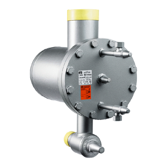
Seite 12: Überblick
ÜBERBLICK OVERVIEW Hochdruckschwimmer-Regler Modelle Float Regulator Models Fig. 2a HR1 – HR3 Fig. 2b HR4 Komplette HR-Austausch Baugruppen Complete HR replacement assemblies Part HR1 / HR1 HR2 / HR3 / HR4 / HS30 HS40 WP2 HR WP3 HR HS50 Steuereinheit, Kap.3.4... -
Seite 13: Überblick Schnittzeichnungen
4.4 Überblick Overview Schnittzeichnungen Sectional drawings Fig. 2c HS30 – HS40 Fig. 2c HS30 – HS40 Fig. 2d HS50... - Seite 14 4.4 Überblick Overview Schnittzeichnungen WPHR / HR1BW Sectional drawings Fig. 2e WP2HR / WP3HR Fig. 2f HR1BW...
- Seite 15 SW 27 6436.AAP270 SW 27 6436.AAP270 SW 27 6436.AAP270 SW 46 6436.AAP460 Schutzkappe zu 13 + 14 + 12 HR 1BW + 50 spindle cap for 13+14+12 HR 1BW + 50 SW 27 6436.AAP270 SW 27 6436.AAP270 SW 27 6436.AAP270 SW 27 6436.AAP270...
- Seite 16 ø 40x16 3591.000117 Spannstift zu 53 locking pin for 53 ---------- ----.------ ---------- ----.------ ø 3x30 5723.AA0302 Flachkopfschraube / Bolzen ( HR 4 ) pan head screw/bolt M4x5 5117.AB30A4 M4x5 5117.AB30A4 ø 4x25x22 5724.A00401 Zugstange / Druckstab tow/pressure bar ø 3x__ ----.------...
-
Seite 17: Abmessungen
ABMESSUNGEN Fig. 3a DIMENSIONS HR 1 - 3 Ausführung mit Ventilen Execution with valves Ausführung ohne Ventile, Schedule 40 Stutzen Execution without valves, Schedule 40 connections Gewicht d x s d x s1 Weight mmxmm mmxmm 26,9x2,3 26,9x2,9 71,5 42,4x2,6... - Seite 18 Abmessungen Fig. 3b Dimensions HR 4 HR4 mit Absperrventilen am Eintritt und Austritt HR4 with stop-valves at inlet and outlet HR4 mit Schedule 40 Anschluss-stutzen HR4 with Schedule 40 connections...
- Seite 19 Abmessungen Fig. 3c Dimensions HS 30 -40 HS30 /HS40 mit Austrittsventil HS30 /HS40 with outlet stop-valve HS30 /HS40 mit Schedule 40 Anschlüssen HS30 /HS40 with Schedule 40 connections Gewicht d3xs d4xs Weight mmxmm mmxmm HS30 219,1 114,3x3,6 60,3x2,9 HS40 323,9 168,3x4,5 88,9x5,6 Gewicht d3xs1...
- Seite 20 Abmessungen Fig. 3d Dimensions HS 50 HS50 mit Austrittsventil HS50 with stop-valve at the outlet HS50 mit Schedule 40 Anschluss-Stutzen HS50 with Schedule 40 connections...
- Seite 21 Abmessungen Dimensions WPHR / HR1BW Fig. 3e WP2HR / WP3HR Gewicht Weight mmxmm WP2HR 42,4x2,6 WP3HR 60,3x2,9 WP3HR- 60,3x2,9 65bar Gewicht Weight inch inch inch inch inch inch inch inch inchxinch WP2HR 7.87 3.94 10.83 9.06 9.84 7.64 18.7 18.11 1.67x0.1 57.32 WP3HR...
-
Seite 22: Geänderte Ventilstellungen
Fig. 4a GEÄNDERTE VENTILSTELLUNGEN MODIFIED VALVE POSITIONS HR 1 - 3... - Seite 23 Ventilstellungen Fig. 4b Modified Valve Positions HR 4...
-
Seite 24: Funktionsbeschreibung
FUNKTIONSBESCHREIBUNG DESCRIPTION OF OPERATION Der Hochdruckschwimmer-Regler entspannt alles auf The high-pressure float regulator expands all liquid refriger- ant condensed on the high-pressure side of the system to der Hochdruckseite anfallende Kältemittel auf die Nie- derdruckseite, ohne jedoch Gas durchzulassen. Durch the low-pressure, but prevents any gas from flowing diese einfache mechanische Methode wird eine äußerst through the regulator. -
Seite 25: Abtauen Von Verdampfergruppen
Auch hier ist ein Hochdruckschwimmer-Regler zwischen The system uses a float regulator between condenser Verflüssiger und Abscheider montiert, der das Kondensat and surge drum, this expands the liquid refrigerant to the auf den Mitteldruck entspannt. Ein zweiter Regler wird intermediate pressure. A second regulator is used to verwendet, um das Kältemittel zur Niederdruckseite zu expand the liquid refrigerant further to the low-pressure entspannen. -
Seite 26: Hr1Bw Zur Ölrückführung
5.1.4 HR1BW for oil return Alternatively the HR1BW can be used for an oil return. Alternativ kann der HR 1 BW auch für eine Ölrückführung eingesetzt werden. Hierzu wird der Regler an der tiefsten Therefore the HR1BW should be placed at the lowest spot of the oil separator. -
Seite 27: Schwimmer-Regelung
HS Reglern vorgesehen. balls to be integrated in the HS type regulators. With the WP HR the ball float is open at the bottom. Due Beim WP HR sind die Schwimmerkugeln unten offen. Durch to gas formation within the ball it will move upwards, ex- Gasansammlung innerhalb der Kugel schwimmt diese auf und posing a part of the orifice area. -
Seite 28: Anlagen Mit Verschlossener Unterdruckdüse
HR Regler mit ver- oil coolers of ammonia screw compressors, the HR regu- schlossener Unterdruckdüse bestellt werden, siehe Fig. 8a. lator must be ordered with closed low-pressure nozzle, (Bei einer solchen Sonderbestellung wird der Hochdruck- see fig. -
Seite 29: Hs-Regler Ohne Unterdruckdüse
5.3.2 HS-Regler ohne Unterdruckdüse 5.3.2 HS regulators without low pressure nozzle Die HS Regler Modelle HS31 – HS33, HS41 – HS43 sowie HS regulator models HS31 – HS33, HS41 – HS43 as well HS51 und HS53 werden ohne Unterdruckdüse ausgeliefert. as HS51 and HS53 are delivered without low pressure nozzle. -
Seite 30: Planungshinweise
These dimensions are not valid for the HR1BW (and HS regulators without low pressure nozzle), which cannot be gers montiert werden darf und auf WP HR, die nicht unter- halb des Verflüssigers montiert werden dürfen. Der WPHR installed above the condenser and the model WP HR that must not be installed below the condenser. - Seite 31 Anordnung des Hochdruckschwimmer-Reglers Fig. 11 Arrangement of the high pressure float regulator Der Regler kann in der Nähe des Niederdruckteils der Kälte- The regulator can be positioned and installed near to the anlage angeordnet werden, sodass die zu isolierende low-pressure side of the refrigerant plant, so the length of Einspritz-Leitung kurz bemessen werden kann.
-
Seite 32: Parallelschaltung Der Regler
Fig. 12b Fig. 12a Ausführung bei parallel geschalteten Verflüssigern Application with parallel condensers 6.3.3 Parallelschaltung der Regler 6.3.3 Parallel Installation of float regulator Eine Parallelschaltung der Hochdruckschwimmer-Regler ist Parallel installation of float regulators is particularly favour- besonders günstig, wenn die Anlage in Teillast oder im unte- able in case of part load or low capacity operation. -
Seite 33: Zulaufleitung
Die Zulaufleitung ist so zu bemessen, dass die Geschwin- The liquid feed line shall be sized so that the velocity of the digkeit des Kondensats unter 1 m/s bleibt. Dies ist gewähr- liquid refrigerant does not exceed 1 m/s. This will be... -
Seite 34: Automatische Ventile In Der Zulaufleitung
6.4.3 Automatische Ventile in der Zulaufleitung 6.4.3 Automatic valves in the liquid feed line Automatische Ventile sind in der Zulaufleitung grundsätzlich The use of automatic valves in the liquid feed line should zu vermeiden. Sollten diese dennoch benötigt werden, emp- generally be avoided. -
Seite 35: Transport Und Lagerung
The piping system is to be clean and free of any mois- • ture. Hochdruckschwimmer-Regler werden im Werk The HR float regulator has undergone a pressure einer Druckprüfung mit Mineralkältemaschinenöl test with mineral refrigerant machine oil in the unterzogen. Wenn die Regler in einer Anlage ein- factory. -
Seite 36: Montageanleitung
ßen halb geöffnet sein und mit einem feuchten Tuch gekühlt werden. Beim Anschweißen an die Stutzen des WP HR , HR4 und When welding to the connections of the WP HR, HR4, HS HS bzw. an ohne Ventile ausgelieferten Stutzen, ist darauf or to the connections without valves, make sure the heat of welding will not damage the O-ring at the outlet. -
Seite 37: Inbetriebnahme
Kältemittel zu entleeren. need to taken out. Wenn Wartungsarbeiten am Hochdruckschwimmer- When the high-pressure float regulator HR is to be maintained, the housing must be completely de- Regler HR durchgeführt werden sollen, muss das Gehäuse drucklos sein und das Kältemittel vollstän-... - Seite 38 HR1 – HR3 (Siehe hierzu auch Fig. 16a und 16b) HR1 – HR3 (refer to Fig. 16a and 16b): Entfernen Sie bei den Typen HR1 bis HR 3 das Ge- For access remove the housing of types HR 1 to •...
-
Seite 39: Austausch Der Hebelpackung
HR4 und HS50 (siehe dazu Schnittzeichnung 2b und 2d) HR4 and HS50 (see also sectional drawings 2b and 2d) Um den Deckel-Flansch, Pos. 11, abnehmen zu In order to take the cover flange, pos. 11 off, you need • • können muss zunächst die Schutzkappe, Pos. -
Seite 40: Austausch Der Ventilpackung
Gleitringdichtungen von Verdichtern im Vacuum laufen, ist eine automatische Entlüftungseinrichtung sehr zu empfehlen! The following sketch (fig. 17) shows the optional WITT gas Das nachfolgend (Fig. 17) dargestellte WITT-Zubehör purge equipment designed to be used for correct purging. (kann optional bestellt werden) wird zur Entlüftung ge- The equipment consists of a special water container that nutzt. -
Seite 41: Erweiterung Der Unterdruckdüse
Purging must be carried out carefully as the water may Die Entlüftung ist auf jedenfalls vorsichtig vorzunehmen, da over a period of time evaporate allowing ammonia to das Wasser während des unter Umständen länger dauern- atmosphere also. The regulator should only be fitted with den Vorgangs verdampfen kann und dann Ammoniak aus- this air purger in a frost-free location to avoid the water treten kann. -
Seite 42: Luft In Der Kälteanlage
• • das Vorhandensein von Einbauten wie z.B. Filtern, There are internal filters, etc, • • eine ungewöhnlich hohe Platzierung des HR über The regulator is positioned too high above the • • dem Verflüssigerausgang oder condenser eine unisolierte Leitungsführung in heißer Umge- The liquid supply line is installed uninsulated in •... -
Seite 43: Plattenverflüssiger
12.5 PLATTENVERFLÜSSIGER 12.5 PLATE TYPE CONDENSER For plate in shell type condensers with thin channels Bei Plattenverflüssigern besteht die Verbindung zwischen Eintritt und Austritt aus dünnen Kanälen, die häufig unter- that are loaded unequally from an internal hot gas con- nection between inlet a properly sized siphon is ex- schiedlich belastet sind. - Seite 44 STÖRUNGSANALYSE: TROUBLE SHOOTING Erscheinung Ursachen und Behebung Symptom Possible Causes - Zu viel Luft im System - Too much air in the system - Zu klein dimensionierter Regler? - Too small selected regulator? - Eintritts-/Austrittventil verschlossen? - Closed inlet-/outlet valve? Regulator does not open - Zu große Druckdifferenz? - Too high pressure difference?
-
Seite 46: Th. Witt Kältemaschinenfabrik Gmbh
TH.WITT Kältemaschinenfabrik GmbH Lukasstraße 32 52070 Aachen, Germany • Tel. +49 (0)2 41 1 82 08 - 0 Fax +49 (0)2 41 1 82 08 - 49 info @ th-witt.com...