Kapitel
Inhaltsverzeichnis
Fehlerbehebung

Verwandte Anleitungen für Stahl 9170 Serie


Inhaltszusammenfassung für Stahl 9170 Serie
- Seite 1 Betriebsanleitung Operating instructions Additional languages www.stahl-ex.com DE EN Schaltverstärker Switching repeater Reihe 9170/.1 Series 9170/.1...
- Seite 3 Betriebsanleitung Additional languages www.stahl-ex.com Schaltverstärker Reihe 9170/.1...
-
Seite 4: Inhaltsverzeichnis
Inhaltsverzeichnis Allgemeine Angaben ...................3 Hersteller ......................3 Angaben zur Betriebsanleitung ................3 Weitere Dokumente ....................3 Konformität zu Normen und Bestimmungen ............3 Erläuterung der Symbole ..................4 Symbole in der Betriebsanleitung ...............4 Warnhinweise .....................4 Symbole am Gerät ....................5 Sicherheitshinweise ....................5 Aufbewahrung der Betriebsanleitung ..............5 Qualifikation des Personals ................5 Sichere Verwendung ...................6 Umbauten und Änderungen ................7... -
Seite 5: Allgemeine Angaben
• FMEDA Report • Safety Manual 9170 Weitere Sprachen, siehe www.stahl-ex.com. Konformität zu Normen und Bestimmungen Siehe Zertifikate und EU-Konformitätserklärung: www.stahl-ex.com. Das Gerät verfügt über eine IECEx-Zulassung. Siehe IECEx-Homepage: http://iecex.iec.ch/ Weitere nationale Zertifikate stehen unter dem folgenden Link zum Download bereit: http://www.r-stahl.com/downloads/certificates.html. -
Seite 6: Erläuterung Der Symbole
Erläuterung der Symbole Erläuterung der Symbole Symbole in der Betriebsanleitung Symbol Bedeutung Tipps und Empfehlungen zum Gebrauch des Geräts Gefahr durch explosionsfähige Atmosphäre Gefahr durch spannungsführende Teile Warnhinweise Warnhinweise unbedingt befolgen, um das konstruktive und durch den Betrieb bedingte Risiko zu minimieren. Die Warnhinweise sind wie folgt aufgebaut: •... -
Seite 7: Symbole Am Gerät
Normen und Bestimmungen umfasst. Für Tätigkeiten in explosionsgefährdeten Bereichen sind weitere Kenntnisse erforderlich! R. STAHL empfiehlt einen Kenntnisstand, der in folgenden Normen beschrieben wird: • IEC/EN 60079-14 (Projektierung, Auswahl und Errichtung elektrischer Anlagen) • IEC/EN 60079-17 (Prüfung und Instandhaltung elektrischer Anlagen) •... -
Seite 8: Sichere Verwendung
• Bei Betriebsbedingungen, die durch die technischen Daten des Geräts nicht abgedeckt werden, unbedingt bei der R. STAHL Schaltgeräte GmbH rückfragen. • Für Schäden, die durch fehlerhaften oder unzulässigen Einsatz des Geräts sowie durch Nichtbeachtung dieser Betriebsanleitung entstehen, besteht keine Haftung. -
Seite 9: Umbauten Und Änderungen
Funktion und Geräteaufbau Umbauten und Änderungen GEFAHR Explosionsgefahr durch Umbauten und Änderungen am Gerät! Nichtbeachten führt zu schweren oder tödlichen Verletzungen. • Gerät nicht umbauen oder verändern. Für Schäden, die durch Umbauten und Änderungen entstehen, besteht keine Haftung und keine Gewährleistung. Funktion und Geräteaufbau GEFAHR Explosionsgefahr durch zweckentfremdete Verwendung! -
Seite 10: Geräteaufbau
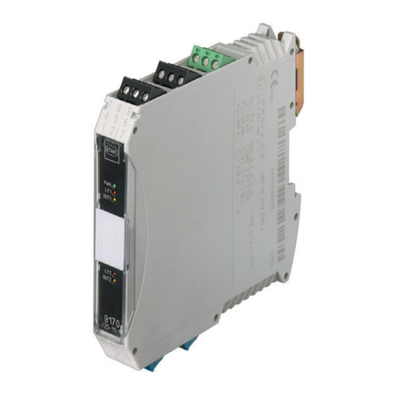
Funktion und Geräteaufbau Geräteaufbau Gerätelement Beschreibung Schwarze/ Anschlussklemmen für den sicheren Bereich grüne Klemmen LED "PWR", grün Anzeige Hilfsenergie LED "LF1", rot Anzeige Leitungsfehlererkennung für Kanal 1 LED "LF2", rot Anzeige Leitungsfehlererkennung für Kanal 2 DIP-Schalter "LF1" Aktivierung der Leitungsfehlererkennung für Kanal 1 DIP-Schalter "LF2"... -
Seite 11: Technische Daten
Technische Daten Technische Daten Kennzeichnung Typbezeichnung 9170/a1-1d-ef (a=1,2; d=0,1,2,3,4; e=1,2; f=1,2) CE-Kennzeichnung 0158 Explosionsschutz Ausführung 9170/.1-1d-1. 9170/.1-1.-2. und mit d=0,1,4 9170/.1-1d-1. mit d=2,3 Global (IECEx) Gas und Staub IECEx BVS 09.0041X IECEx BVS 09.0041X Ex nA nC [ia Ga] IIC T4 Gc [Ex ia Ga] IIC [Ex ia Da] IIIC [Ex ia Da] IIIC... - Seite 12 Technische Daten Reihe 9170 - Ausgang: Signalrelais Technische Daten Ausführung 24 V DC 120 ... 230 V AC 9170/.1-11-11., 9170/21-10-11. 9170/.1-11-21., 9170/21-10-21. Elektrische Daten Hilfsenergie Nennspannung U 24 V DC 120 ... 230 V AC Spannungsbereich 18 ... 31,2 V 96 ...
- Seite 13 Technische Daten Technische Daten Ex i Eingang Eingangssignal gemäß EN 60947-5-6 (NAMUR) Ausgang Max. Belastung DC 250 V / 2 A Max. Belastung AC 250 V / 4 A Max. Schaltleistung 50 W / 1000 VA Fehlererkennung Ex i Eingang Drahtbruch gemäß...
- Seite 14 Technische Daten Reihe 9170 - Ausgang: Elektronik LFT Technische Daten Elektrische Daten Hilfsenergie Nennspannung U 24 V DC Spannungsbereich 18 ... 31,2 V Nennstrom bei U 1 Kanal 28 mA 2 Kanäle 40 mA Verpolschutz Betriebsanzeige LED grün "PWR" Ex i Eingang Eingangssignal gemäß...
-
Seite 15: Projektierung
- flexibel 0,2 ... 1,5 mm – - flexibel mit Aderendhülsen 0,25 ... 1 mm 0,5 ... 1 mm Weitere technische Daten, siehe www.stahl-ex.com. Projektierung HINWEIS Ausfall der installierten Geräte im Schaltschrank durch zu hohe Umgebungstemperatur! Nichtbeachten kann zu Sachschäden führen. -
Seite 16: Montage Und Installation
Montage und Installation Montage und Installation Der Gerät ist außerhalb explosionsgefährdeter Bereiche zu installieren. Die Geräte-Typen 9170/.1-.0-1., 9170/.1-.1-1. und 9170/.1-.4-1. sind auch für den Betrieb in explosionsgefährdeten Bereichen der Zone 2 und Zone 22 zugelassen. GEFAHR Explosionsgefahr bei Installation ohne Feldgehäuse! Nichtbeachten führt zu schweren oder tödlichen Verletzungen! •... - Seite 17 Montage und Installation Montage 07391E00 15551E00 07392E00 Gewünschte Anzahl der pac-Bus-Elemente auf Klemmenset am Anfang pac-Bus-Elemente Hutschiene aufrasten. und am Ende einstecken. zusammenstecken. Demontage • In umgekehrter Reihenfolge wie bei Montage vorgehen. 8.2.2 Montage / Demontage von Gerät auf Hutschiene und pac-Bus Montage auf Hutschiene •...
-
Seite 18: Montage / Demontage Auf Pac-Träger
Montage und Installation 8.2.3 Montage / Demontage auf pac-Träger Zur Montage und Demontage auf pac-Träger siehe Handbuch pac-Träger 9195. 8.2.4 Montage / Demontage steckbare Klemmen Alle Geräte sind mit steckbaren Klemmen ausgestattet. Montage • Klemme in Gerät stecken, bis Klemme einrastet. Demontage •... -
Seite 19: Anschluss Der Speisung
Parametrierung und Inbetriebnahme 8.3.2 Prinzipschaltbilder Siehe Geräteaufdruck. 8.3.3 Anschluss der Speisung Geräte-Typ Art der Versorgung Anschluss 9170/.1-1.-1. Direkte Versorgung des Geräts über Grüne Klemme "7+" und "9-" 24 V-Anschluss Versorgung über pac-Bus pac-Bus-Klemme "1+" und "2-" 9170/.1-1.-21. Direkte Versorgung des Geräts über Grüne Klemme "L"... -
Seite 20: Parametrierungen
Betrieb Parametrierungen DIP-Schalterstellungen für Leitungsfehlererkennung LF und Invertierung der Wirkungsrichtung INV Leitungsfehlererkennung LF Wirkungsrichtung invertiert INV deaktiviert/OFF *) aktiviert/ON deaktiviert/OFF *) aktiviert/ON Kanal 1 INV1 INV1 INV1 INV1 Kanal 2 INV2 INV2 INV2 INV2 07456E 07455E 15527E 15528E *) Standardeinstellung bei Auslieferung Die DIP-Schalterstellungen "LF"... -
Seite 21: Anzeigen
Eingängen fehlt das Potential zur Erzeugung vom High Level. Wenn sich der Fehler mit den genannten Vorgehensweisen nicht beheben lässt: • An R. STAHL Schaltgeräte GmbH wenden. Zur schnellen Bearbeitung folgende Angaben bereithalten: • Typ und Seriennummer des Geräts • Kaufdaten •... -
Seite 22: Instandhaltung, Wartung, Reparatur
Die geltenden nationalen Bestimmungen im Einsatzland beachten. 11.3 Reparatur GEFAHR Explosionsgefahr durch unsachgemäße Reparatur! Nichtbeachten führt zu schweren oder tödlichen Verletzungen. • Reparaturen an den Geräten ausschließlich durch R. STAHL Schaltgeräte GmbH ausführen lassen. Schaltverstärker 200089 / 9170612310 Reihe 9170/.1 2017-10-04·BA00·III·de·08... -
Seite 23: Rücksendung
Reinigung 11.4 Rücksendung • Rücksendung bzw. Verpackung der Geräte nur in Absprache mit R. STAHL durchführen! Dazu mit der zuständigen Vertretung von R. STAHL Kontakt aufnehmen. Für die Rücksendung im Reparatur- bzw. Servicefall steht der Kundenservice von R. STAHL zur Verfügung. -
Seite 24: Zubehör Und Ersatzteile
HINWEIS Fehlfunktion oder Geräteschaden durch den Einsatz nicht originaler Bauteile. Nichtbeachten kann Sachschaden verursachen! • Nur Original-Zubehör und Original-Ersatzteile der R. STAHL Schaltgeräte GmbH verwenden. Zubehör und Ersatzteile, siehe Datenblatt auf Homepage www.stahl-ex.com. Schaltverstärker 200089 / 9170612310 Reihe 9170/.1 2017-10-04·BA00·III·de·08... - Seite 25 Operating instructions Additional languages www.stahl-ex.com Switching repeater Series 9170/.1...
- Seite 26 Contents General Information ....................3 Manufacturer .......................3 Information regarding the Operating Instructions ..........3 Further Documents .....................3 Conformity with Standards and Regulations ............3 Explanation of the Symbols ................4 Symbols in these Operating Instructions ............4 Warning Notes ....................4 Symbols on the Device ..................5 Safety Notes .......................5 Operating Instructions Storage ................5 Personnel Qualification ..................5...
-
Seite 27: General Information
• Safety manual 9170 For further languages, see www.stahl-ex.com. Conformity with Standards and Regulations See certificates and EU Declaration of Conformity: www.stahl-ex.com. The device has IECEx approval. See IECEx homepage: http://iecex.iec.ch/ Further national certificates can be downloaded via the following link: http://www.r-stahl.com/downloads/certificates.html. -
Seite 28: Explanation Of The Symbols
Explanation of the Symbols Explanation of the Symbols Symbols in these Operating Instructions Symbol Meaning Tips and recommendations on the use of the device Danger due to explosive atmosphere Danger due to live components Warning Notes Warnings must be observed under all circumstances, in order to minimize the risk due to construction and operation. -
Seite 29: Symbols On The Device
Specialists who perform these tasks must have a level of knowledge that meets applicable national standards and regulations. Additional knowledge is required for tasks in hazardous areas! R. STAHL recommends having a level of knowledge equal to that described in the following standards: •... -
Seite 30: Safe Use
• Ensure that the contents of these operating instructions are fully understood by the personnel in charge. • Always consult with R. STAHL Schaltgeräte GmbH if using the device under operating conditions which are not covered by the technical data. -
Seite 31: Modifications And Alterations
Function and Device Design Modifications and Alterations DANGER Explosion hazard due to modifications and alterations to the device! Non-compliance results in severe or fatal injuries. • Do not modify or alter the device. No liability or warranty for damage resulting from modifications and alterations. -
Seite 32: Device Design
Function and Device Design Device Design Device component Description Black/green Connection terminals for the safe area terminals "PWR" LED, green Auxiliary power indication "LF1" LED, red Indication of line fault detection for channel 1 "LF2" LED, red Indication of line fault detection for channel 2 DIP switch "LF1"... -
Seite 33: Technical Data
Technical Data Technical Data Marking Type designation 9170/a1-1d-ef (a=1,2; d=0,1,2,3,4; e=1,2; f=1,2) CE marking 0158 Explosion Protection Version 9170/.1-1d-1. 9170/.1-1.-2. and with d=0,1,4 9170/.1-1d-1. with d=2,3 Global (IECEx) Gas and dust IECEx BVS 09.0041X IECEx BVS 09.0041X Ex nA nC [ia Ga] IIC T4 Gc [Ex ia Ga] IIC [Ex ia Da] IIIC [Ex ia Da] IIIC... - Seite 34 Technical Data Series 9170 - Output: signal relay Technical Data Version 24 V DC 120 to 230 V AC 9170/.1-11-11., 9170/21-10-11. 9170/.1-11-21., 9170/21-10-21. Electrical data Auxiliary power Nominal voltage U 24 V DC 120 to 230 V AC Voltage range 18 to 31.2 V 96 to 253 V Nominal current...
- Seite 35 Technical Data Technical Data Ex i input Input signal acc. to EN 60947-5-6 (NAMUR) Output Maximum load DC 250 V / 2 A Maximum load AC 250 V / 4 A Max. switching 50 W / 1000 VA capacity Error detection Ex i input Open circuit according to EN 60947-5-6...
- Seite 36 Technical Data Series 9170 - Output: LFT electronics Technical Data Electrical data Auxiliary power Nominal voltage U 24 V DC Voltage range 18 to 31.2 V Nominal current at U 1 channel 28 mA 2 channels 40 mA Polarity reversal protection Operation indication LED green "PWR"...
-
Seite 37: Engineering
– - flexible with core end 0.25 to 1 mm 0.5 to 1 mm sleeves For further technical data, see www.stahl-ex.com. Engineering NOTICE Failure of the devices installed in the cabinet caused by too high ambient temperature! Non-compliance can result in material damage. -
Seite 38: Mounting And Installation
Mounting and Installation Mounting and Installation The device is to be installed outside of hazardous areas. Device types 9170/.1-.0-1., 9170/.1-.1-1. and 9170/.1-.4-1. are also approved for operation in hazardous areas of Zone 2 and Zone 22. DANGER Explosion hazard due to installation without field enclosure! Non-compliance results in severe or fatal injuries! •... - Seite 39 Mounting and Installation Mounting 07391E00 15551E00 07392E00 Connect the required Engage the pac-Bus Connect the terminal set at number of pac-Bus elements on the DIN rail. the beginning and at the elements. end. Dismounting • Proceed in the reverse order to mounting. 8.2.2 Mounting / Dismounting of the Device on Top Hat Rail and pac-Bus Mounting on top hat rail •...
-
Seite 40: Installation
Mounting and Installation 8.2.3 Mounting / Dismounting on pac-Carrier To mount and dismount the pac-Carrier, see manual for the 9195 pac-Carrier. 8.2.4 Mounting / Dismounting pluggable Terminals All devices are equipped with pluggable terminals. Mounting • Plug the terminal into the device until the terminal engages. Dismounting •... -
Seite 41: Parameterization And Commissioning
Parameterization and Commissioning 8.3.2 Schematic Diagrams See device labelling. 8.3.3 Connection of Supply Device type Type of supply Connector 9170/.1-1.-1. Direct supply of the device via 24 V connection Green terminals "7+" and "9-" Supply via pac-Bus pac-Bus terminal "1+" and "2-" 9170/.1-1.-21. -
Seite 42: Parameterizations
Operation Parameterizations DIP switch positions for line fault detection LF and inversion of the direction of action INV Line fault detection LF Direction of action inverted INV Deactivated/OFF *) Activated/ON Deactivated/OFF *) Activated/ON Chan- nel 1 INV1 INV1 INV1 INV1 Chan- INV2 INV2... -
Seite 43: Indications
High Level is missing. If the error cannot be eliminated using the mentioned procedures: • Contact R. STAHL Schaltgeräte GmbH. For fast processing, have the following information ready: • Type and serial number of the device • Purchase information •... -
Seite 44: Maintenance And Repair
Observe the relevant national regulations in the country of use. 11.3 Repair DANGER Explosion hazard due to improper repair! Non-compliance results in severe or fatal injuries. • Repair work on the devices must be performed only by R. STAHL Schaltgeräte GmbH. Switching repeater 200089 / 9170612310 Series 9170/.1 2017-10-04·BA00·III·en·08... -
Seite 45: Returning The Device
• Only return or package the devices after consulting R. STAHL! Contact the responsible representative at R. STAHL for this. R. STAHL's customer service is available to handle returns if repair or service is required. Only return or package the devices after contacting and consulting R. STAHL! •... -
Seite 46: Accessories And Spare Parts
Malfunction or damage to the device due to the use of non-original components. Non-compliance can result in material damage. • Use only original accessories and spare parts from R. STAHL Schaltgeräte GmbH. For accessories and spare parts, see data sheet on our homepage www.stahl-ex.com. - Seite 48 Type 9170/*1-**-1* Type 9170/*1-**-2* (for 24 V DC) (for 120 /230 V AC or with power relay) (only at (only at 9170/2) 9170/2) The Switching Repeater Type 9170/*1-*d-1* (d = 0, 1, 4) is an The Switching Repeater Type 9170/*1-**-2* and Type associated apparatus as well as a nonincendive apparatus for 9170/*1-*d-** (d = 2, 3) is an associated apparatus located in installation in non-hazardous or Class 1, Division 2 or Zone 2...