LEYBOLD MODEL 1901 Gebrauchsanleitung
Temperatur-anzeigegerät

Inhaltszusammenfassung für LEYBOLD MODEL 1901
- Seite 1 Applikations- LEYBOLD VACUUM Vakuum-Lösungen Unterstützung Service GA 12.309/3 MODEL 1901 Temperatur-Anzeigegerät Temperature Indicator Kat.-Nr. / Cat. No. 136 45 Gebrauchsanleitung Operating Instructions...
-
Seite 2: Inhaltsverzeichnis
Typ D ist im EPROM gespeichert. Bedienung ......7 Das MODEL 1901 hat zwei Schaltpunkte mit dazu 2.2.1 Einstellungen des Geräts prüfen . -
Seite 3: Technische Daten
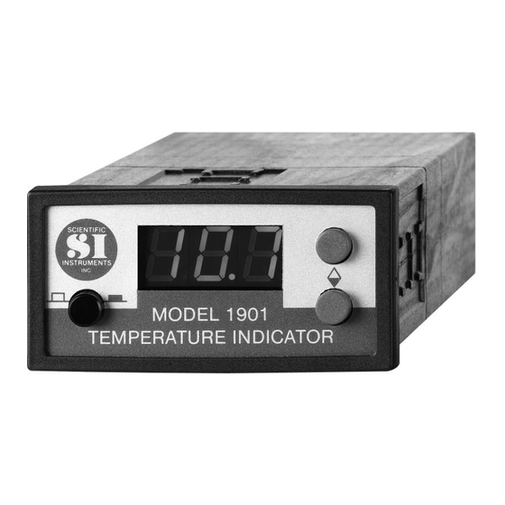
2 Relais (Öffner und Schließer) Abb. 1 Temperatur-Anzeigegerät 28 VDC @ 0.25 A RS 232 Schnittstelle a) Temperatur-Ausgabe Bestelldaten b) Externes Ändern der Schaltpunkte MODEL 1901 136 45 °C Umgebungs-Temperatur 10 - 35 HV-Messleitung mit Winkelstecker, 10 m lang 500 085... - Seite 4 Abb. 2 Maßzeichnung; Maße in mm GA 12.309/3 - 11/2002...
- Seite 5 Zum Nachrüsten der Si-Dioden in Kryo- pumpen liegt den Dioden eine Anleitung und eine Tabelle mit der Temperatur/ Widerstands-Charakteristik bei. mittlerer Anstieg -33 mV/K mittlerer Anstieg -2,4 mV/K 20 40 60 80 Temperatur K (Kelvin) Abb. 3 Standard Temperatur/Spannung-(Widerstands-) Kennlinie von Si-Dioden Typ D GA 12.309/3 - 11/2002...
- Seite 6 Senden (Ausgang) 5 - Relais 2 C grün Empfangen (Eingang) 6 - Relais 2 NC gelb nicht angeschlossen NO = normally open = Schließer NC = normally closed = Öffner Abb. 4 Rückseite des MODEL 1901 GA 12.309/3 - 11/2002...
-
Seite 7: Betrieb
Betrieb Anschlüsse Bedienung Alle Ein- und Ausgänge sind an der Rückseite des Einige Augenblicke nach dem Anlegen der Spannung Geräts. zeigt das Gerät die Temperatur an, die von der ange- schlossenen Silizium-Diode gemessen wird. Auf • Netzteil an den Eingang Versorgungsspannung Wunsch kann der Bediener anschließen •... -
Seite 8: Einstellungen Des Geräts Prüfen
Die Taste AB nochmal drücken. Das Gerät zeigt an, peratur, die Taste AUF drücken und wieder loslassen, welche Silizium-Dioden-Charakteristik in der Soft- um Schaltpunkt 1 anzuzeigen, oder die Taste AB ware benutzt wird. Für die Leybold-Silizium-Diode drücken und wieder loslassen, um Schaltpunkt 2 Typ D erscheint 470. anzuzeigen •... -
Seite 9: Rs-232-Betrieb
RS-232-Betrieb Beispiel: Der Schaltpunkt 12,3 K für Relais 2 wird über- mittelt als: Den Computer auf eine Baudrate von 9600, no parity, 8 S2123 <CR> Datenbits und 1 Stopbit einstellen. Da der Anzeigebereich des Geräts bis 450 K geht, ist der größte sinnvolle Wert für einen Schaltpunkt 4500. -
Seite 10: Anbau Von Si-Dioden An Leybold-Kaltköpfe
Notwendiges Zubehör Montage (siehe Abb. 6) (siehe Abb. 5). Wir empfehlen, die Anschlußleitung der Si-Diode 2 bis 3 Si-Diode, Typ „D“ komplett mit Anschlußleitung, mal um das Zylinderrohr der 2. Stufe des Kaltkopfes zu 600 mm lang Kat.-Nr. 890 89 wickeln. - Seite 11 Abb. 5 Benötigte Teile für die Montage von Si-Dioden; siehe Abschnitt 3.1 Erläuterungen zur Abb. 6 1 2. Kaltkopfstufe 2 Kammer und Kapillare des Dampfdruck-Thermometers 3 Mutter M 2 4 Unterlegscheibe und Federring 5 Si-Diode 6 Indiumscheibe 7 Senkkopfschraube M 2x8 Abb.
-
Seite 12: Eg-Konformitätserklärung
EG-Konformitätserklärung Hiermit erklären wir, die Leybold Vakuum GmbH, daß die nachfolgend Die Produkte entsprechen folgenden Richtlinien: bezeichneten Produkte aufgrund ihrer Konzipierung und Bauart sowie • EG-Niederspannungsrichtlinie (73/23/EWG) in der von uns in Verkehr gebrachten Ausführung den einschlägigen grundlegenden Sicherheits- und Gesundheitsanforderungen der EG- •... - Seite 13 GA 12.309/3 - 11/2002...
- Seite 25 GA 12.309/3 - 11/2002...
- Seite 26 LEYBOLD VAKUUM GmbH Bonner Strasse 498 (Bayenthal) D-50968 Köln Tel.: (0221) 347-0 Fax: (0221) 347-1250 http://www.leyboldvac.de e-mail:documentation@leyboldvac.de...