IAMS 0001 / 0011 / 0010 ContentS Warning! ................Symbol identification ............Safety instructions .............. How to dismantle the IAMS Devices ......... When front LED lights red / display shows AO.ER .... Advanced features ............. Application ................. Technical characteristics ............
WArnIng! The IAMS devices are designed for connection to hazardous electric voltages. Ignoring this warning can result in severe personal injury or mechanical damage. To avoid the risk of electric shock and fire, the safety instruc generAL tions of this manual must be observed and the guidelines fol lowed.
SyMboL IDentIfICAtIon triangle with an exclamation mark: Warning / demand. Potentially lethal situations. the Ce mark proves the compliance of the devices with the essential requirements of the directives. the double insulation symbol shows that the devices are protected by double or reinforced insulation. SAfety InStrUCtIonS DefInItIonS: Hazardous voltages have been defined as the ranges: 75 to 1500 Volt DC, and...
Seite 5
Mounting and connection of the devices should comply with national legislation for mounting of electric materials, i.a. wire cross section, protective fuse, and location. Descriptions of input / output and supply connections are shown in the block diagram and side label. The following apply to fixed hazardous voltagesconnected devices: The max.
HoW to DISMAntLe tHe IAMS DeVICeS First, remember to demount the connectors with hazardous voltages. picture 1: Detach the device from the DIN rail by lifting the bottom lock. When front LeD lights red / display shows Ao.er IAMS0001 and IAMS0011 are designed with a high safety level. Therefore, a continuous measurement of the outgoing current is carried out on a 4...20 mA output signal.
IAMS 0001 / 0011 / 0010 • Input for RTD, TC, Ohm, potentiometer, mA and V • 2-wire supply > 16 V • FM-approved for installation in Div. 2 • Output for current, voltage and 2 relays • Universal AC or DC supply Advanced features • Programmable via detachable display front (PGMMOD00), process...
pgMMoD00 DISpLAy / progrAMMIng front functionality The simple and easily understandable menu structure and the explanatory help texts guide you effortless ly and automatically through the setup steps, thus making the product very easy to use. Functions and setup options are described in the section ”Setup / operating the function keys”.
AppLICAtIonS Input signals: Volt Potenti Current RTD and lin.R ometer Connect., wires Output signals: Relays 10 V 10 V Analogue, 0/4...20 mA and voltage Supply: 21.6...253 VAC 19.2...300 VDC...
order codes IAMS0001 Universal transmitter mA out IAMS0011 Universal transmitter mA / 2 relays IAMS0010 Universal limit switch with 2 relays pgMMoD00 Display / programming module electrical specifications Specifications range: 20°C to +60°C Common specifications: Supply voltage, universal ......21.6...253 VAC, or 19.2...300 VDC Max.
Seite 11
Basic values Input Basic Temperature type accuracy coefficient ≤ ±4 µA ≤ ±0.4 µA / °C ≤ ±20 µV ≤ ±2 µV / °C Volt ≤ ±0.2°C ≤ ±0.01°C / °C Pt100 ≤ ±0.1 Ω ≤ ±0.01 Ω / °C Linear resistance ≤...
Seite 12
Cable resistance per wire (max.), RTD ..50 Ω Sensor current, RTD ........Nom. 0.2 mA Effect of sensor cable resistance (3 / 4wire), RTD ......... < 0.002 Ω / Ω Sensor error detection, RTD ....... Yes Short circuit detection, RTD ......< 15 Ω tC input: Min.
Seite 13
Current output: Signal range (span) ........0...20 mA Programmable signal ranges ...... 0...20 / 4...20 / 20...0 and 20...4 mA Load (max.) ..........20 mA / 800 Ω / 16 VDC Load stability ..........≤ 0.01% of span / 100 Ω Sensor error detection ........
Visualisation of sensor error detection and input signal outside range Sensor error check: Setup Sensor error detection: R1, ERR.ACT=NONE R2, ERR.ACT=NONE, OUT.ERR=NONE Else: Outside range readout (IN.LO, IN.HI): If the valid range of the A/D converter or the polynomial is exceeded Input Range Readout Limit IN.LO...
SetUp / operAtIng tHe fUnCtIon keyS Documentation for routing diagram. In general: When setting up the IAMS devices, you will be guided through all parameters and you can choose the settings which fit the application. For each menu there is a scrolling help text which is automatically shown in line 3 on the display.
Seite 19
password protection: Programming access can be blocked by assigning a password. The password is saved in the device in order to ensure a high degree of protection against unauthorised modifications to the setup. Default password 2008 allows access to all setup modules. Signal and sensor error info via pgMMoD00 Sensor error (see limits in the table) is displayed as SE.BR (sensor break) or SE.SH (sensor short).
Increasing/decreasing: The relays can be set to activate at increasing or decreasing input signal. Delay: An ON and an OFF delay can be set on both relays in the range 0...3600 s. Hysteresis: A hysteresis can be set at 0.1...25% of the span or of the selected display range.
Seite 21
Auto diagnosis The unit performs an advanced auto diagnosis of the internal circuits. The following possible errors can by displayed in the front unit PGMMOD00. CJ.ER CJC sensor defect or CJC temperature outside range FL.ER Flash error AO.ER No load on the current output (only for S4...20 mA / S20...4 mA) NO.CO ...
Seite 22
Safety readback When the device is delivered with default configuration, the SIL function is disabled. The safety readback function (loop surveillance) can be selected in the menu O.RANGE, thus enabling the device to run in SIL mode. In order to enable the SIL functionality, the menu item S4...20 mA or S20...4 mA must be selected.
Seite 23
Power up Fast setpoint adjustment 50.0 and relay test R1 SETP Txt 57 1 Increase setpoint 2 Decrease setpoint 75.0 3 Save and exit the menu R2 SETP 50.0 Txt 57 1 and 2 simultaneously = change relay state 12.0 9.ADV VOLT 8.ANA CURR 6.SPT LIN.R 0000 1.INP...
roUtIng DIAgrAM If no key is activated for 1 minute, the display will return to the default state 1.0 without saving setup changes (except INP.SIM and REL.SIM). 1 Increase value / choose next parameter 2 Decrease value / choose previous parameter 3 Save the chosen value and proceed to the next menu Hold 3 Back to previous menu / return to menu 1.0 without saving 1111...
SCroLLIng HeLp text In DISpLAy LIne 3 No error action undefined status at error [01] Set correct password [24] Open relay contact at error [02] Select setup module or NO to store and exit Close relay contact at error [03] Select temperature input Hold relay status at error...
graphic depiction of relay action Setpoint Relay units Relay units Hysteresis = 10 Setpoint = 50 Setpoint = 50 Hysteresis = 10 Off N.O. On N.O. Off N.O. Off N.O. On N.O. Off N.O. Off N.C. On N.C. Off N.C. On N.C. On N.C. On N.C. relay action: Increasing relay action: Decreasing graphic depiction of relay action Window Relay units...
Seite 30
IAMS 0001 / 0011 / 0010 SoMMAIre Avertissement ! ..............30 Signification des symboles ..........31 Démontage des dispositifs IAMS ........33 Quand la LED rouge s’allume / l’indicateur affiche AO.ER Options avancées............... 34 Applications ................ 34 Caractéristiques techniques..........34 PGMMOD00 indicateur / façade de programmation ..
AVertISSeMent ! Les dispositifs IAMS sont conçus pour supporter une connexion à des tensions électriques dangereuses. Si vous ne tenez pas compte de cet avertissement, cela peut causer des dommages corporels ou des dégâts mécaniques. Pour éviter les risques d’électrocution et d’incendie, conformez InforMA...
SIgnIfICAtIon DeS SyMboLeS triangle avec point d’exclamation : Attention ! Si vous ne respectez pas les instructions, la situation pourrait être fatale. Le signe Ce indique que les dispositifs sont conformes aux exigences des directives. Ce symbole indique que les dispositifs sont protégés par une isolation double ou renforcée.
Red Lion Controls BV, Printerweg 103821, AD Amersfoort, The Netherlands. Phone: +31 (0) 334723225, fax: +31 (0) 334893793. Toll Free from UK and France: 00800 REDLIONS (00800 733 54667 ou à red Lion Controls Worldwide Headquarters, 20 Willow Springs Circle, York, PA 17406 USA, Phone: +1 (717) 7676511, Fax: +1 (717) 7640839.
DeMontAge DeS DISpoSItIfS IAMS Tout d’abord, n’oubliez pas de démonter les connecteurs où règnent des ten sions dangereuses. figure 1 : Débloquez le verrou inférieur pour dégager le dispositif du rail DIN. quand la LeD rouge s’allume / l’indicateur affiche Ao.er Les IAMS0001 et IAMS 0011 ont été...
IAMS 0001 / 0011 / 0010 • Entrées : RTD, TC, Ohm, potentiomètre, mA et V • Alimentation 2-fils > 16 V • Approbation FM pour installation en Div. 2 • Sorties : courant, tension et 2 relais • Alimentation multi-tension ca ou cc options avancées...
pgMMoD00 InDICAteUr / fAçADe De progrAMMAtIon fonctionnalité Le menu simple, structuré à l’aide de questions pour la configuration, guide automatiquement l’utilisateur par un menu déroulant et rend ainsi aisé l’utilisation du produit. Voir la description des fonctions et options de configuration dans la section «...
AppLICAtIonS Signaux d’entrée : Ten Potenti Courant sion RTD et R lin. omètre Connection, fils Signaux de sortie : Relais 10 V 10 V Analogique, 0/4...20 mA et tension Alimentation : 21,6...253 Vca 19,2...300 Vcc...
references de commande IAMS0001 transmetteur universel, sortie mA IAMS0011 transmetteur universel, mA / 2 relais IAMS0010 relais à seuils avec 2 relais pgMMoD00 Afficheur / façade de programmation Spécifications électriques plage des spécifications : 20°C à +60°C Spécifications communes : Tension d’alimentation universelle ....
Seite 39
Valeurs de base Type Précision Coefficient d’entrée de base de température ≤ ±4 µA ≤ ±0,4 µA / °C ≤ ±20 µV ≤ ±2 µV / °C Volt ≤ ±0,2°C ≤ ±0,01°C / °C Pt100 ≤ ±0,1 Ω ≤ ±0,01 Ω / °C Résistance linéaire ≤...
Seite 40
Entrée pour types RTD : Pt10, Pt20, Pt50, Pt100, Pt200, Pt250, Pt300, Pt400, Pt500, Pt1000 Ni50, Ni100, Ni120, Ni1000 Résistance de ligne max. par fil, RTD ..50 Ω Courant de capteur, RTD ......Nom. 0,2 mA Effet de la résistance de ligne 3...
Seite 41
Résistance d’entrée........Nom. 10 MΩ Sortie courant : Gamme de signal (EC) ........ 0...20 mA Gammes de signal programmables .... 0...20 / 4...20 / 20...0 et 20...4 mA Charge (max.) ..........20 mA / 800 Ω / 16 Vcc Stabilité de charge ........≤ 0,01% de l’EC / 100 Ω Détection erreur capteur ......
Indication de la détection erreur capteur et du signal d’entrée hors d’échelle Vérifications erreur capteur : Configuration Détection erreur capteur R1, ERR.ACT=NONE R2, ERR.ACT=NONE, OUT.ERR=NONE. Autre : Indication de dépassement d’échelle (IN.LO, IN.HI) : En dépassement de l’echelle définie du convertisseur A/D ou des standards températures Entrée Plage Affichage...
progrAMMAtIon / operAtIon DeS toUCHeS De fonCtIon Documentation pour le diagramme de programmation. généralités : Lors de la configuration des dispositif IAMS vous êtes guidés tout au long des paramètres du menu ; ainsi vous pouvez choisir le réglage qui correspond à votre application. Pour chaque menu il y a un texte d’aide qui défile en ligne 3 de l’indicateur.
protection par mot de passe : L’accès à la programmation peut être bloqué par un mot de passe. Ce mot de passe est sauvegardé dans le dispositif afin d’assurer un haut niveau de protection contre les modifications non autorisées. Le mot de passe usine 2008 permet l’accès à tous les menus de configuration.
Délais : Fonctions Délai “on” ou “off” peuvent être choisies pour les 2 relais entre 0...3600 s. Hystérésis : L’hystérésis peut être configuré entre 0,1 et 25% de l’échelle ou de la gamme d’affichage. fonctions avancées L’unité donne accès à un certain nombre de fonctions avancées qui sont acces sibles en répondant «...
Autodiagnostic Le dispositif effectue la fonction autodiagnostic des circuits internes. Voici les erreurs possibles affichées sur le PGMMOD00 : CJ.ER Défaut capteur CSF ou température CSF en dépassement d’échelle FL.ER Erreur flash AO.ER La sortie courant est sans charge (uniquement pour les signaux S4...20 mA / S20...4 mA) NO.CO ...
Seite 50
fonction securité Par défaut les appareils sont livrés avec la fonction SIL inactive. La fonction sécurité (surveillance de boucle) peut être selectionnée sur le menu O.RANGE ce qui permet à la carte de fonctionner en mode SIL. De plus il faut que la sortie S4...20mA ou S20...4 mA soit validée.
Seite 51
Power up Réglage rapide des consignes 50.0 et test des relais R1 SETP Txt 57 1 Incrémentation de la consigne 2 Décrémentation de la consigne 75.0 3 Sauvegarde des valeurs et sorti du menu R2 SETP 50.0 Txt 57 1 et 2 simultanément = le relais change d’état 12.0 9.ADV VOLT...
DIAgrAMMe De progrAMMAtIon Si aucune touche n’est actionnée pendant 1 minute, l’indicateur retourne sur l’état défaut sans sauvegarde des modifications éventuelles apportées à la configuration. 1 Incrémenter la valeur / choisir paramètre suivant 2 Décrémenter la valeur / choisir paramètre précédent 3 Valider les valeurs choisies et fin du menu Maintien 3 Retour au menu précédent / retour au menu 1.0 sans sauvegarde 1111...
MenU DéroULAnt en LIgne 3 De L’InDICAteUr Pas d’action d’erreur état nondéfini en cas d’erreur [01] Entrer mot de passe correct [24] Ouvrir contact du relais en cas d’erreur [02] Sélectionner module de configuration ou NO pour Fermer contact du relais en cas d’erreur sauvegarder et sortir du menu Maintenir état du relais en cas d’erreur [03]...
Illustration graphique de l’action de relais consigne Unités de relais Unités de relais L’hystérésis = 10 Consigne = 50 Consigne = 50 L’hystérésis = 10 Off N.O. On N.O. Off N.O. Off N.O. On N.O. Off N.O. Off N.C. On N.C. Off N.C. On N.C. On N.C. On N.C. Action du relais : Montante Action du relais : Descendante Illustration graphique de l’action de relais fenêtre...
Seite 58
IAMS 0001 / 0011 / 0010 InHALtSVerZeICHnIS WARNUNG! ................ 58 Zeichenerklärungen ............59 Sicherheitsregeln ..............59 Zerlegung des IAMSgerätes ..........61 Wenn die Front LED rot leuchtet / Display zeigt AO.ER ..61 Erweiterte Merkmale ............62 Verwendung ................ 62 Technische Merkmale ............
WArnUng! Dieses Gerät ist für den Anschluss an lebensgefährliche elek trische Spannungen gebaut. Missachtung dieser Warnung kann zu schweren Verletzungen oder mechanischer Zerstörung führen. Um eine Gefährdung durch Stromstöße oder Brand zu vermei ALLge den müssen die Sicherheitsregeln des Handbuches eingehalten, MeIneS und die Anweisungen befolgt werden.
ZeICHenerkLÄrUngen Dreieck mit Ausrufungszeichen: Warnung / Vorschrift. Vorgänge, die zu lebensgefährlichen Situationen führen können. Die CeMarke ist das sichtbare Zeichen dafür, dass das Gerät die Vorschriften erfüllt. Doppelte Isolierung ist das Symbol dafür, dass das Gerät besondere Anforderungen an die Isolierung erfüllt. SICHerHeItSregeLn DefInItIonen: gefährliche Spannungen sind definitionsgemäß...
Seite 61
Circle, York, PA 17406 USA, Phone: +1 (717) 7676511, Fax: +1 (717) 7640839) Kontakt aufnehmen. Die Installation und der Anschluss des Gerätes haben in Übereinstimmung mit den geltenden Regeln des jeweiligen Landes bez. der Installation elektrischer Apparaturen zu erfolgen, u.a. bezüglich Leitungsquerschnitt, (elektrischer) Vor Absicherung und Positionierung.
ZerLegUng DeS IAMSgerÄteS Zunächst ist gefährliche Spannung von den Anschlussklemmen zu trennen. Abbildung 1: Das Gerät wird von der DINSchiene gelöst, indem man den unteren Verschluss löst. Wenn die front LeD rot leuchtet / Display zeigt Ao.er Die IAMS0001 und IAMS0011 sind ist mit einem hohen Grad an Sicherheit konstruiert.
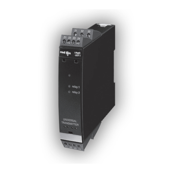
IAMS 0001 / 0011 / 0010 • Eingang für WTH, TE, Ohm, Potmeter, mA und V • 2-Draht-Versorgung > 16 V • FM-Zulassung für Installation in Div. 2 • Ausgänge für Strom, Spannung und 2 Relais • Universelle Versorgung mit AC oder DC erweiterte Merkmale • Programmierbar mittels abnehmbare Frontdisplay (PGMMOD00), Prozess...
pgMMoD00 DISpLAy / progrAMMIerfront funktionallität Die einfache Menüstruktur leitet automatisch durch die relevanten Einstellungen. Der scrollende Hilfetext macht es sehr einfach diese Geräte einzusetzen. Sie finden weitere Beschreibungen der Funktionen und Programmierungsmög lichkeiten im Abschnitt ”Konfiguration / Bedienung der Funktionstasten”. Anwendungen • Kommunikationsschnittstelle zur Änderung der operativen Parameter in der IAMSGeräte.
Visualisierung: Sensorfehlererkennung und eingangssignal außerhalb des bereichs Sensorfehlerprüfung: Konfiguration Fühlerfehlererkennung R1, ERR.ACT=NONE R2, ERR.ACT=NONE, OUT.ERR=NONE. Sonst: Außerhalb des Bereichs Anzeige (IN.LO, IN.HI): Bei Verlassen des Gewählten Bereichs des A/DWandlers oder des Polynoms. Eingang Bereich Anzeige Grenze IN.LO < 25 mV 0...1 V / 0,2...1 V IN.HI >...
Display Anzeige unter Min. / über Max. (1999, 9999): Eingang Bereich Anzeige Grenze 1999 Display Anzeige <1999 Alle Alle 9999 Display Anzeige >9999 grenzen fühlerfehlererkennung Fühlerfehlererkennung (SE.BR, SE.SH): Eingang Bereich Anzeige Grenze CURR Schleife unterbrochen (4...20 mA) SE.BR <= 3,6 mA; > = 21 mA Ω POTM Alle, SE.BR auf alle 3Leiter SE.BR...
konfIgUrAtIon / beDIenUng Der fUnktIonStASten Dokumentation für das Flussdiagramm. grundsätzliches: Bei der Konfiguration des IAMSGerätes werden Sie durch alle Parameter gelei tet und Sie können die Einstellungen wählen, welche zur Applikation passt. Für jedes Menü existiert ein scrollender Hilfetext welcher automatisch in der 3.
passwortschutz: Der Zugriff auf die Programmierung kann mit der Eingabe eines Passwortes blockiert werden. Das Passwort wird im Gerät gespeichert, um den höchsten Grad an Schutz gegen nicht autorisierte Änderungen der Konfiguration sicherzustellen. Bei Eingabe des MasterPasswortes 2008 sind alle Konfigurationsmenüs erreichbar. Signal und Sensorfehlerinformation per programmierfront Sensorfehler (s. Grenzen im Diagramm), wird als SE.BR (Sensorfehler) oder SE.SH (Fühlerkurzschluß) angezeigt.
Signalanstieg/abfall: Das Relais kann bei ansteigenden oder abfallenden Eingangssignal aktiviert werden. Verzögerung: Ein AN sowohl als auch ein AUSVerzögerungssignal kann für beide Relais im Bereich von 0...3600 s programmiert werden. Hysterese: Die Hysterese kann im Bereich von 0,1…25% der Spanne oder des Displaybereichs eingestellt werden.
Selbstdiagnose Das Gerät führt eine Selbstdiagnose des internen Kreises durch. Die folgenden Fehlermeldungen können im Frontdisplay PGMMOD00 angezeigt werden. CJ.ER CJCFühler defekt oder Temperatur außerhalb des Bereichs FL.ER Fehler im Flash AO.ER Der Stromausgang ist unbelastet (nur für S4...20 mA / S20...4 mA) NO.CO ...
Sicherheitsüberwachung Wenn das Gerät mit der StandardKonfiguration ausgeliefert wird, ist die SILFunktion deaktiviert. Die Sicherheitüberwachungsfunktion (Loop Überwachung) kann im Menü O. RANGE gewählt werden, damit das Gerät in den SILModus übergeht. Um die SILFunktion zu aktivieren, muss der Menüpunkt S4...20 mA oder S20...40 mA gewählt werden. Bitte beachten Sie jedoch, wenn die Sicherheitsüberwachung aktiviert ist, wird ein Sensorfehler als Fehler des analogen Ausgangssignals angezeigt.
Seite 79
Power up Schnelleinstellung von Sollwert 50.0 und Relaistest R1 SETP 1 Sollwert ansteigend Txt 57 2 Sollwert fallend 3 Speichern und Menü verlassen 75.0 1 und 2 gleichzeitig drücken = Relaiszustand R2 SETP 50.0 Txt 57 ändern 12.0 9.ADV VOLT 8.ANA CURR 6.SPT LIN.R 0000 1.INP POTM...
fLUSSDIAgrAMM Wenn für eine Dauer von 1 Minute keine Taste betätigt wird, kehrt das Display auf den Menüpunkt 1.0 zurück und eventuelle Änderungen in der Konfiguration werden nicht gespeichert. 1 Wert erhöhen / nächsten Parameter wählen 2 Wert herabsetzen / vorheringen Parameter Wählen 3 Parameter speicher und nächsten Parameter wählen Halten 3 Zurück zum vorheringen Parameter / zurück zum Menüpunkt 1.0 ohne Speicherung von Änderungen 1111...
SCroLLenDer HILfetext IM DISpLAy ZeILe 3 Keine Fehlerwirkung undefinierter Status bei Fehler [01] Einstellung des korrekten Passwortes [24] [02] Auswahl Konfigurationsmenü oder NO um zu speichern Geöffneter Relaiskontakt bei Fehler Geschlossener Relaiskontakt bei Fehler und Menü zu verlassen Hält Relaisstatus bei Fehler [03] Auswahl TemperaturEingang Einstell.
graphische Abbildung der relaisfunktion Sollwert Relaiseinheiten Relaiseinheiten Hysterese = 10 Sollwert = 50 Sollwert = 50 Hysterese = 10 Off N.O. On N.O. Off N.O. Off N.O. On N.O. Off N.O. Off N.C. On N.C. Off N.C. On N.C. On N.C. On N.C. relaisaktion: Steigend relaisaktion: fallend graphische Abbildung der relaisfunktion fenster Relaiseinheiten Relaiseinheiten Hysterese = 5...
Seite 86
York, PA 17406 The Netherlands Phone: +31 (0) 33-4723-225 Phone: +1 (717) 767-6511 Fax: +31 (0) 33-4893-793 Fax: +1 (717) 764-0839 europe@redlion.net sales@redlion.net Toll Free from UK and France: 00800 REDLIONS Red Lion Controls AP (00800 733 54667) Unit 101, XinAn Plaza...