Herunterladen Inhalt Inhalt Diese Seite drucken
Inhaltsverzeichnis

Werbung

Verfügbare Sprachen
  • DE

Verfügbare Sprachen

  • DEUTSCH, seite 1
Saunasteuerung
K1-NEXT
MONTAGE- UND GEBRAUCHSANWEISUNG
Deutsch
Version 06/12
Ident-Nr. 50950066
DE
EN
FR
IT
NL
SV

Werbung

Inhaltsverzeichnis
loading

Inhaltszusammenfassung für Sentiotec 50950066

  • Seite 1 Saunasteuerung K1-NEXT MONTAGE- UND GEBRAUCHSANWEISUNG Deutsch Version 06/12 Ident-Nr. 50950066...
  • Seite 2: Inhaltsverzeichnis

    Montage- und Gebrauchsanweisung S. 2/10 Montageanweisung Allgemeine Sicherheitshinweise ................3 1 Saunasteuerung montieren ................4 2 Ofenfühler mit Übertemperatur-Sicherung montieren ........5 3 Prüfungen .....................5 Technische Daten ....................8 Gebrauchsanweisung Allgemeine Sicherheitshinweise ................6 1 Zu Ihrer Sicherheit ..................7 2 Bedienung ....................7 3 Die Sauna-Innenraumbeleuchtung ein- / ausschalten .........7 4 Bei längeren Betriebspausen ...............7 5 Fehler und mögliche Abhilfe .................7 Technische Daten ....................8...
  • Seite 3: Allgemeine Sicherheitshinweise

    Montageanweisung nur für Fachpersonal S. 3/10 Sehr geehrter Monteur, • Die Montage darf nur durch einen Elektrofachmann oder einer vergleichsweise qualifizierten Person ausge- führt werden. • Arbeiten an der Saunasteuerung dürfen nur im spannungsfreien Zustand ausgeführt werden. • Lesen Sie diese Montageanweisung sorgfältig vor der Montage der Saunasteuerung. Damit nutzen Sie alle Vorteile, die das Gerät bietet und beugen Schäden vor. • Beim Auftreten besonderer Probleme, die in dieser Montageanweisung nicht ausführlich genug behandelt werden, wenden Sie sich zu Ihrer eigenen Sicherheit an Ihren Lieferanten.
  • Seite 4: Saunasteuerung Montieren

    Montageanweisung nur für Fachpersonal S. 4/10 Saunasteuerung montieren Abbildung 1 3 Die Saunasteuerung wird in ca.1,70 Meter Höhe neben der Kabinentür oder gemäß der Kabinenhersteller-Emp- fehlung montiert. Die elektrische Versorgung erfolgt als Festanschluss. Die Qualität der Netzanschlussleitung ist min. H07RN-F. VORSICHT - Schäden am Gerät: Die Saunasteuerung ist spritzwassergeschützt (Schutzgrad IP X4). Trotzdem sollte die Saunasteuerung nicht direkt mit Wasser in Berührung kommen. Die Saunasteuerung an einem trockenen Ort montieren. Die Umgebungsbedingungen von 40°Celsius und einer maximalen Luftfeuchte von 95 Prozent nicht über- schreiten.
  • Seite 5: Ofenfühler Fi Mit Übertemperatursicherung Montieren Abbildung

    Montageanweisung nur für Fachpersonal S. 5/10 Ofenfühler FI mit Übertemperatursicherung montieren Abbildung 2 3 Der Ofenfühler mit Übertemperatursicherung wird in der Saunakabine circa 15 cm unterhalb der Decke ober- halb des Heizsystems, oder nach Angaben des Kabinenherstellers montiert. Der Ofenfühler mit Übertemperatursicherung darf nur mit der beiliegenden bis 150°C temperaturbeständigen Anschlussleitung angeschlossen werden.
  • Seite 6: Allgemeine Sicherheitshinweise

    Gebrauchsanweisung für den Anwender S. 6/10 Sehr geehrter Anwender, • Lesen Sie diese Gebrauchsanweisung sorgfältig vor dem Gebrauch der Saunasteuerung. Damit nutzen Sie alle Vorteile, die das Gerät bietet und beugen Schäden vor. • Beim Auftreten besonderer Probleme, die in dieser Gebrauchsanweisung nicht ausführlich genug behandelt werden, wenden Sie sich zu Ihrer eigenen Sicherheit an Ihren Lieferanten. • Eigenmächtige Änderungen oder Umbauten an der Saunasteuerung sind aus Sicherheitsgründen nicht gestattet. •...
  • Seite 7: Zu Ihrer Sicherheit

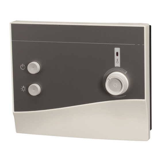
    Gebrauchsanweisung für den Anwender S. 7/10 Zu Ihrer Sicherheit VORSICHT - Schäden am Gerät: Die Saunasteuerung sollte nicht mit Wasser übergossen oder sehr feucht gereinigt werden. Benutzen Sie zum Reinigen ein leicht angefeuchtetes Reinigungstuch, das mit etwas milder Seifenlauge (Spülmittel) versehen ist. Bedienung Abbildung 4 WARNUNG - Brandgefahr: Vor dem Einschalten der Saunasteuerung ist sicher zu stellen, dass keine brennbaren Gegenstände...
  • Seite 8: Wartung

    ......................... Oberregauer Straße 48 A-4844 Regau ......................... T: +43 (0) 7672 27720-567 F: +43 (0) 7672 27720-801 ......................... E-Mail: support@sentiotec.com Technische Daten www.sentiotec.com Abmessungen: L x B x T: 238 x 195 x 73,50 mm Umgebungsbedingungen: Lagertemperatur: -25°C bis + 70°C Umgebungstemperatur: -10°C bis + 40°C Luftfeuchtigkeit: max. 95 %...
  • Seite 9: Anschlussplan

    Montage- und Gebrauchsanweisung S. 9/10 Anschlussplan Saunasteuerung K1-NEXT Abbildung 1 Abbildung 2 WE DO IT FIRST.
  • Seite 10 Montage- und Gebrauchsanweisung S. 10/10 Abbildung 3 Abbildung 4 WE DO IT FIRST.
  • Seite 11 Sauna Control K1-NEXT INSTALLATION- AND OPERATING INSTRUCTIONS English Version 06/12 Ident-Nr. 50950066...
  • Seite 12 Instructions for installation and use P. 2/10 Installation Instructions General Safety Instructions ................13 1 Installing the sauna control .................14 2 Installing the oven sensor with thermal fuse ..........15 3 Checks .......................15 Technical Data ....................18 Operating Instructions General Safety Instructions ................16 1 For your safety ...................17 2 Operation ....................17 3 Switching the interior sauna light on / off ............17 4 After lengthy non-use .................17 5 Errors and possible corrective measures ...........17...
  • Seite 13: General Safety Instructions

    Instructions for installation and use – only for experts P. 3/10 Dear Assembler • Only electricians or a similarly qualified individual may carry out the installation. • Work on the sauna control may be done only if it is disconnected from the power supply. • Carefully read this installation instructions before installing the sauna control. This allows you to use all the advantages offered by the device and avoid damaging it. • If special problems, which are not adequately discussed in these installation instructions, occur, please contact your supplier to ensure your own safety. • For safety reasons, no unilateral changes or reconstructions are permitted on the sauna control. • Technical modifications subject to change. Meaning of the symbols used in the installation instructions: WARNING: non-compliance may lead to severe injury or even death. CAUTION: non-compliance may lead to intermediate to light injury or property damage. NOTE: offers tips in using the device and useful information.
  • Seite 14: Installing The Sauna Control

    Instructions for installation and use – only for experts P. 4/10 Installing the sauna control Diagram 1 3 The sauna control is mounted at a height of approx. 1.70 m beside the cabin door or as directed by the cabin manufacturer. Electrical power comes as a permanent connection. The quality of the mains lead is at least H07RN-F. CAUTION - damage to the device: The sauna control is protected from splashing water (protection class IP X4). Nonetheless, the sauna control must not come into direct contact with water. Install the sauna control in a dry place.
  • Seite 15: Mounting The Stove Sensor Fi With Overtemperature Protector Figure

    Instructions for installation and use – only for experts P. 5/10 Mounting the stove sensor FI with overtemperature protector Figure 2 3 Mount the stove sensor with overtemperature protector FI in the sauna cabin about 15 cm below the ceiling and above the heating system, or in accordance with specifications of the cabin manufacturer. The stove sensor with overtemperature protector can only be connected with the attached 150°C temperature- resistant connecting line. On the outside of the sauna cabin the temperatur resistant connecting line can be ex- tended with customary lines. CAUTION - Double insulation is required: Run the stove sensor line separate to other power cables in the connection range for extra-low voltage of the control.
  • Seite 16: General Safety Instructions

    Instructions for use for the user P. 6/10 Dear User • Carefully read these operating instructions before installing the sauna control. This allows you to use all the advantages offered by the device and avoid damaging it. • If special problems, which are not adequately discussed in this operating instructions, occur, please contact your supplier to ensure your own safety. • For safety reasons, no unilateral changes or reconstructions are permitted on the sauna control. • Technical modifications subject to change. Meaning of the symbols used in the installation instructions: WARNING: non-compliance may lead to severe injury or even death. CAUTION: non-compliance may lead to intermediate to light injury or property damage.
  • Seite 17: For Your Safety

    Instructions for use for the user P. 7/10 For your safety CAUTION - Damage on the device: Do no pour water over the sauna control nor use too much water when cleaning it. To clean it, use a slightly damp cloth with mild soapsuds (rinsing agent). Operation Diagram 4 WARNING - Fire hazard: Before starting the sauna control make sure that there are no flammable objects on the oven.
  • Seite 18: Customer Service

    • Please enter the address of your customer service here: sentiotec GmbH world of wellness ......................... Oberregauer Straße 48 A-4844 Regau ......................... T: +43 (0) 7672 27720-567 F: +43 (0) 7672 27720-801 ......................... E-Mail: support@sentiotec.com Technical Data www.sentiotec.com Dimensions: L x W x H: 238 x 195 x 73,50 mm Ambient conditions: Storage temperature: -25°C to + 70°C Ambient temperature: -10°C to + 40°C Humidity: max. 95% Minimum temperature resistance of the connecting cables: Heating system, light and oven sensor at least 150°C temperature resistance...
  • Seite 19: Wiring Diagram

    Instructions for installation and use P. 9/10 Wiring diagram Sauna control K1-NEXT Figure 1 Figure 2 WE DO IT FIRST.
  • Seite 20 Instructions for installation and use P. 10/10 Figure 3 Figure 4 WE DO IT FIRST.
  • Seite 21 Commande sauna K1-NEXT INSTRUCTIONS DE MONTAGE / MODE D´EMPLOI FRANÇAIS Version 06/12 Ident-Nr. 50950066...
  • Seite 22 Instructions de montage et mode d‘emploi p. 2/10 Instructions de montage Consignes de sécurité générales ..............23 1 Monter la commande du sauna ..............24 2 Monter le capteur du four avec la sécurité élévation de température ..25 3 Contrôles ....................25 Caractéristiques techniques ................28 Mode d’emploi Consignes de sécurité...
  • Seite 23: Instructions De Montage

    Instructions de montage uniquement pour le personnel spécialisé P. 3/10 Très cher monteur, • Le montage ne peut être effectué que par un électricien spécialisé ou une personne ayant des qualifications similaires. • Les travaux sur la commande du sauna ne peuvent être exécutés que si l’appareil est hors tension. • Lisez ces instructions de montage attentivement avant le montage de la commande du sauna. Vous exploiterez ainsi tous les avantages offerts par l’appareil et préviendrez les dommages. • En cas de problèmes particuliers ne pouvant pas être traités avec suffisamment de précision dans ces inst- ructions de montage, adressez-vous pour votre propre sécurité à vos fournisseurs. • Des modifications ou transformations délibérées de la commande du sauna ne sont pas autorisées pour des raisons de sécurité. • Modifications techniques réservées. Signification des symboles utilisés dans les instructions de montage : ATTENTION : en cas de non respect, il existe la possibilité de blessures graves et même mortelles. ATTENTION : en cas de non respect, il existe la possibilité de blessures moyennes à légères ou de dommages matériels. REMARQUE : procure des astuces d’application et des informations utiles.
  • Seite 24: Monter La Commande Du Sauna

    Instructions de montage uniquement pour le personnel spécialisé P. 4/10 Monter la commande du sauna Illustration 1 3 La commande du sauna se monte en hauteur à environ 1,70 mètre à côté de la porte de la cabine ou selon les recommandations du fabricant de la cabine. L’alimentation électrique est effectuée via un raccordement fixe. La qualité du câble d’alimentation secteur est d’au moins H07RN-F. ATTENTION - Dommages à l‘appareil: La commande est protégée contre les projections d’eau (niveau de protection IP X4). La commande ne doit cependant pas entrer directement en contact avec de l’eau. Monter la commande dans un endroit sec. Ne pas dépasser les conditions d’environnement de 40° Celsius et une humidité de l’air maximale de 95 pour cent.
  • Seite 25: Contrôles

    Instructions de montage uniquement pour le personnel spécialisé P. 5/10 Montage de la sonde du poêle FI équipée d’un dispositif de protection contre la surchauffe - Illustration 2 3 Montez la sonde du poêle, avec le dispositif de protection contre la surchauffe, dans la cabine du sauna, à environ 15 cm du plafond et au-dessus du système de chauffage, ou conformément aux instructions du fabricant de la cabine. La sonde du poêle, équipée du dispositif de protection contre la surchauffe, ne peut être raccordée qu’au moyen des câbles fournis, résistant à une température de max. 150 °C. PRUDENCE – une double isolation est nécessaire : Le câble de la sonde du poêle doit être séparé des autres câbles d’alimentation dans la zone de raccorde- ment pour les très basses tensions de l’unité de commande. Les câbles à isolation simple doivent être protégés par un tube (double isolation). 1. Placez le câble à 4 pôles 5 à l’endroit de montage de la sonde du poêle 4, dans la paroi de la cabine, et fixez-le à l’aide de colliers de câble. 2. Séparez deux demi-coques 1 de la sonde du poêle 4 et raccordez quatre connecteurs du câble résistant aux hautes températures, en respectant le schéma de raccordement.
  • Seite 26: Caractéristiques Techniques

    Mode d‘emploi pour l‘utilisateur P. 6/10 Très cher utilisateur, • Lisez ce mode d’emploi attentivement avant l’utilisation de la commande du sauna. Vous exploiterez ainsi tous les avantages offerts par l’appareil et préviendrez les dommages. • En cas de problèmes particuliers ne pouvant pas être traités avec suffisamment de précision dans ce mode d’emploi, adressez-vous pour votre propre sécurité à vos fournisseurs. • Des modifications ou transformations délibérées de la commande du sauna ne sont pas autorisées pour des raisons de sécurité. • Modifications techniques réservées. Signification des symboles utilisés dans le mode d’emploi: ATTENTION: en cas de non respect, il existe la possibilité de blessures graves et même mortelles. ATTENTION: en cas de non respect, il existe la possibilité de blessures moyennes à légères ou de dommages matériels. REMARQUE: procure des astuces d’application et des informations utiles. Danger d‘incendie Conservez soigneusement ces instructions de montage et mode d’emploi à proximité de la commande pour pouvoir consulter à tout moment les consignes de sécurité et les informations importantes quant à l’utilisation. Consignes de sécurité générales Respectez aussi les consignes de sécurité spéciales relatives à chaque chapitre.
  • Seite 27: Pour Votre Sécurité

    Mode d‘emploi pour l‘utilisateur P. 7/10 Pour votre sécurité ATTENTION - Dommages à l‘appareil : La commande du sauna ne doit pas recevoir de l’eau ou être nettoyée en milieu très humide. Utilisez pour le nettoyage une étoffe légèrement humidifiée et imprégnée d’une lessive de savon non agressive. Suite Illustration 4 AVERTISSEMENT - Risque d‘incendie : Avant l’enclenchement de la commande, on doit s’assurer qu’aucun objet combustible ne se trouve sur le four. 1. Mettre en marche la commande du sauna avec l’interrupteur MARCHE / ARRÊT 4. Un autotest se produit. 2. Régler avec le bouton tournant 2 la température du sauna souhaitée. Noter la température qui vous est le plus agréable avec un crayon de papier par exemple.
  • Seite 28: Service Clients

    ......................... Oberregauer Straße 48 A-4844 Regau ......................... T: +43 (0) 7672 27720-567 F: +43 (0) 7672 27720-801 ......................... Caractéristiques techniques E-Mail: support@sentiotec.com www.sentiotec.com Les gabarits: L x l x P: 238 x 195 x 73,50 mm Conditions de l’environnement: Température de stockage: -25°C bis + 70°C Température ambiante: -10°C bis + 40°C Humidité...
  • Seite 29: Plan De Connexion

    Instructions de montage et mode d‘emploi p. 9/10 Plan de connexion Commande sauna K1-NEXT Figure 1 Figure 2 WE DO IT FIRST.
  • Seite 30 Instructions de montage et mode d‘emploi p. 10/10 Figure 3 Figure 4 WE DO IT FIRST.
  • Seite 31 Controllo per sauna K1-NEXT ISTRUZIONI PER IL MONTAGGIO / ISTRUZIONI PER I´USO ITALIANO Version 06/12 Ident-Nr. 50950066...
  • Seite 32 Istruzioni per uso e montaggio P. 2/10 Istruzioni per il montaggio Indicazioni generali sulla sicurezza ..............33 1 Montare il controllo per sauna ..............34 2 Montare il sensore del forno con fusibile di sovratemperatura ....35 3 Prove ......................35 Dati tecnici ......................38 Istruzioni per l’uso Indicazioni generali sulla sicurezza ..............36 1 Per la vostra sicurezza ................37 2 Uso ......................37 3 Accendere/spegnere l’illuminazione all’interno della sauna.......37 4 Pause prolungate di funzionamento ............37...
  • Seite 33: Istruzioni Per Il Montaggio

    Istruzioni per il montaggio solo per personale specializzato P. 3/10 Caro montatore, • Il montaggio può essere eseguito solo da un elettricista specializzato o da una persona con una qualifica equivalente. • I lavori al controllo per sauna devono essere eseguiti solo in assenza di tensione. • Legga queste istruzioni per il montaggio con cura prima di effettuare il montaggio del controllo per sauna. Così facendo sarà possibile usufruire di tutti i vantaggi che l’apparecchio offre ed evitare danni. • Nel caso si verifichino problemi particolari, che non sono stati trattati in modo esauriente in queste istruzioni per il montaggio, per la propria sicurezza, Si rivolga al proprio fornitore. • Modifiche o cambiamenti non autorizzati sul controllo per sauna non sono consentiti per motivi di sicurezza. • Con riserva di modifiche tecniche. Significato dei simboli utilizzati nelle istruzioni per il montaggio: AVVERTIMENTO: in caso di inosservanza c’è la possibilità di un ferimento grave o addirittura mortale. ATTENZIONE: in caso di inosservanza c’è la possibilità di un ferimento da medio a leggero o di danni agli oggetti. NOTA: dà consigli per l’applicazione ed informazioni utili. Conservare con cura queste istruzioni per il montaggio e per l’uso vicino al controllo per sauna, per poter raggiungere in qualsiasi momento le indicazioni sulla sicurezza e le informazioni importanti per l’uso.
  • Seite 34: Montare Il Controllo Per Sauna

    Istruzioni per il montaggio solo per personale specializzato P. 4/10 Montare il controllo per sauna Figura 1 3 Il controllo per sauna viene montato a ca.1,70 metri di altezza accanto alla porta della cabina o secondo il consiglio del costruttore della cabina. L’alimentazione elettrica si effettua come allacciamento fisso. La qualità della linea di allacciamento alla rete è almeno H07RN-F. ATTENZIONE - Danni all‘apparecchio: Il controllo per sauna è protetto dagli schizzi d’acqua (grado di protezione IP X4). Ciononostante il control- lo per sauna non deve entrare in contatto diretto con l’acqua. Montare il controllo per sauna in un luogo asciutto.
  • Seite 35: Prove

    Istruzioni per il montaggio solo per personale specializzato P. 5/10 Montaggio del sensore della stufa FI con fusibile di sovratemperatura Immagine 2 3 Il fusibile di sovratemperatura viene montato nella cabina della sauna circa 15 cm sotto il tetto e sopra il sistema di riscaldamento, oppure secondo le indicazioni del produttore delle cabine. Il sensore della stufa con fusibile di sovratemperatura può essere collegato solamente al cavo di collegamento in dotazione, resistente ad una temperatura fino a 150°.
  • Seite 36: Dati Tecnici

    Istruzioni per l’uso per l’utilizzatore P. 6/10 Caro utente • Legga queste istruzioni per l’uso con cura, prima di utilizzare il controllo per sauna. Così facendo sarà possibile usufruire di tutti i vantaggi che l’apparecchio offre ed evitare danni. • Nel caso si verifichino particolari problemi, che in queste istruzioni per l’uso non sono stati trattati in modo esauriente, per la propria sicurezza, Si rivolga al proprio fornitore. • Modifiche o cambiamenti non autorizzati sul controllo per sauna non sono consentiti per motivi di sicurezza. • Con riserva di modifiche tecniche. Significato dei simboli utilizzati nelle istruzioni per l’uso: AVVERTIMENTO: in caso di inosservanza c’è la possibilità di un ferimento grave o addirittura mortale. ATTENZIONE: in caso di inosservanza c’è la possibilità di un ferimento da medio a leggero o di danni agli oggetti. NOTA: dà consigli per l’applicazione ed informazioni utili. Pericolo d‘incendio Conservare con cura queste istruzioni per il montaggio e per l’uso vicino al controllo per sauna, per poter raggiungere in qualsiasi momento le indicazioni sulla sicurezza e le informazioni importanti per l’uso.
  • Seite 37: Per La Vostra Sicurezza

    Istruzioni per l’uso per l’utilizzatore P. 7/10 Per la vostra sicurezza ATTENZIONE - Danni all‘apparecchio: Non versare acqua sopra il controllo per sauna e non pulirlo con un panno molto bagnato. Per pulire utilizzare un panno di pulizia leggermente imbevuto con un detergente delicato (detersivo per piatti). Uso Figura 4 AVVERTIMENTO - Pericolo d‘incendio: Prima di accendere il controllo per sauna assicurarsi che nessun oggetto infiammabile si trovi sul forno.
  • Seite 38: Servizio Clienti

    ......................... Oberregauer Straße 48 A-4844 Regau ......................... T: +43 (0) 7672 27720-567 F: +43 (0) 7672 27720-801 ......................... E-Mail: support@sentiotec.com Dati tecnici www.sentiotec.com Dimensioni: L x L x P: 238 x 195 x 73,50 mm Condizioni ambientali: Temperatura d’immagazzinamento: da -25°C a + 70°C Temperatura ambiente: da -10°C a + 40°C Umidità dell’aria: max. 95 %...
  • Seite 39: Schema Di Collegamento

    Istruzioni per uso e montaggio P. 9/10 Schema di collegamento Controllo per sauna K1-NEXT Figura 1 Figura 2 WE DO IT FIRST.
  • Seite 40 Istruzioni per uso e montaggio P. 10/10 Figura 3 Figura 4 WE DO IT FIRST.
  • Seite 41 Saunabesturing K1-NEXT MONTAGEAANWIJZING / GEBRUIKSAANWIJZING Nederlands Version 06/12 Ident-Nr. 50950066...
  • Seite 42 Montage- en gebruiksaanwijzing Pag. 2/10 Montageaanwijzing Algemene veiligheidsaanwijzingen ..............43 1 Saunabesturing monteren ................44 2 Ovenvoeler met oververhittingbeveiliging monteren ........45 3 Controles ....................45 Technische gegevens ..................48 Gebruiksaanwijzing Algemene veiligheidsaanwijzingen ..............46 1 Voor uw veiligheid ..................47 2 Bediening ....................47 3 De binnenverlichting van de sauna in- /uitschakelen .........47 4 Bij langere bedrijfspauzes ................47 5 Fouten en mogelijke hulp ................47 Technische gegevens ..................48...
  • Seite 43: Algemene Veiligheidsaanwijzingen

    Montagehandleiding uitsluitend voor vakpersoneel Pag. 3/10 Geachte monteur, • De montage mag alleen door een elektricien of een vergelijkbaar gekwalificeerd persoon uitgevoerd worden. • Werkzaamheden aan de saunabesturing mogen alleen in spanningsvrije toestand uitgevoerd worden. • Lees deze montageaanwijzing zorgvuldig door vóór de montage van de saunabesturing. Daardoor maakt u gebruik van alle voordelen, die het apparaat biedt en voorkomt u schades. • Bij het optreden van bijzondere problemen, die in deze montageaanwijzing niet uitvoerig genoegd behandeld worden, dient u zich, voor uw eigen veiligheid, aan uw leverancier te wenden. • Eigenhandige veranderingen of verbouwingen aan de saunabesturing zijn uit veiligheidsoverweging niet toegestaan. • Technische veranderingen voorbehouden. Betekenis van de in de montageaanwijzing toegepaste tekens: WAARSCHUWING: bij het niet in acht nemen bestaat de mogelijkheid van een zware of zelfs dodelijke verwonding. VOORZICHTIG: bij het niet in acht nemen bestaat de mogelijkheid van lichte tot middelmatige verwondingen of materiële schades.
  • Seite 44: Saunabesturing Monteren

    Montagehandleiding uitsluitend voor vakpersoneel Pag. 4/10 Saunabesturing monteren Afbeelding 1 3 De saunabesturing wordt op ca.1,70 meter hoogte naast de cabinedeur of volgens de aanwijzingen van de fab- rikant van de cabine gemonteerd. De elektrische verzorging geschiedt als vaste aansluiting. De kwaliteit van de netaansluitleiding is min. H07RN-F. VOORZICHTIG - Schades aan het apparaat: De saunabesturing is beschermd tegen spatwater (beschermingsgraad IP X4). Desondanks dient de sau- nabesturing niet direct met water in contact te komen. De saunabesturing op een droge plaats monteren. De omgevingsvoorwaarden van 40°Celsius en een maximale luchtvochtigheid van 95 procent niet over- schrijden.
  • Seite 45: Controles

    Montagehandleiding uitsluitend voor vakpersoneel Pag. 5/10 Kachelvoeler FI met beveiliging voor te hoge temperatuur monteren Afbeelding 2 3 De kachelvoeler met beveiliging voor te hoge temperatuur wordt in de saunacabine gemonteerd op circa 15 cm onder het plafond boven het verwarmingssysteem, of volgens de gegevens van de cabineproducent. De kachelvoeler met beveiliging voor te hoge temperatuur mag uitsluitend met de bijgevoegde temperatuurbes- tendige aansluitleiding tot 150°C worden aangesloten. VOORZICHTIG –...
  • Seite 46: Technische Gegevens

    Gebruiksaanwijzing voor de gebruiker Pag. 6/10 Geachte gebruiker, • Lees deze gebruiksaanwijzing zorgvuldig door vóór het gebruik van de saunabesturing. Daarmee gebruikt u alle voordelen, die het apparaat biedt en voorkomt u schades. • Bij het optreden van bijzondere problemen, die in deze gebruiksaanwijzing niet uitvoerig genoeg behandeld worden, dient u zich, voor uw eigen veiligheid, aan uw leverancier te wenden. • Eigenhandig doorgevoerde veranderingen of verbouwingen aan de saunabesturing zijn uit veiligheidsover- wegingen niet toegestaan. • Technische veranderingen voorbehouden. Betekenis van de in gebruiksaanwijzing toegepaste tekens: WAARSCHUWING: bij het niet in acht nemen bestaat de mogelijkheid van een zware of zelfs dodelijke verwonding. VOORZICHTIG: bij het niet in acht nemen bestaat van de mogelijkheid van lichte tot middelmatige verwondingen of ma- teriële schades.
  • Seite 47: Voor Uw Veiligheid

    Gebruiksaanwijzing voor de gebruiker Pag. 7/10 Voor uw veiligheid VOORZICHTIG - Schades aan het apparaat: Er mag geen water over de saunabesturing gegoten worden en ook niet te vochtig reinigen. Gebruik voor het reinigen een licht vochtige reinigingsdoek, eventueel voorzien van een milde zeepop- lossing (afwasmiddel).
  • Seite 48: Technische Gegevens

    ......................... world of wellness Oberregauer Straße 48 ......................... A-4844 Regau T: +43 (0) 7672 27720-567 ......................... F: +43 (0) 7672 27720-801 Technische gegevens E-Mail: support@sentiotec.com www.sentiotec.com Afmetingen: L x B x D: 238 x 195 x 73,50 mm Omgevingsvoorwaarden: Opslagtemperatuur: -25°C tot + 70°C Omgevingstemperatuur: -10°C tot + 40°C Luchtvochtigheid: max. 95 % Minimale temperatuurbestendigheid van de aansluitleidingen: Verwarmingssysteem, licht- en ovenvoeler minimaal 150 °C temperatuurbestendigheid...
  • Seite 49: Aansluitschema

    Montage- en gebruiksaanwijzing Pag. 9/10 Aansluitschema Saunabesturing K1-NEXT Afbeelding 1 Afbeelding 2 WE DO IT FIRST.
  • Seite 50 Montage- en gebruiksaanwijzing Pag. 10/10 Afbeelding 3 Afbeelding 4 WE DO IT FIRST.
  • Seite 51 Bastustyrning K1-NEXT MONTERINGS- OCH BRUKSANVISNING svenska Version 06/12 Ident-Nr. 50950066...
  • Seite 52 Monterings- och bruksanvisning S. 2/10 Monteringsanvisning Allmänna säkerhetsanvisningar.................3 1 Montera bastustyrningen ................4 2 Montera kaminsensorn med övertemperatursäkring ........5 3 Kontroller .....................5 Tekniska data ....................8 Bruksanvisning Allmänna säkerhetsanvisningar.................6 1 För er säkerhet .....................7 2 Manövrering ....................7 3 Slå till / från bastuinnerbelysningen .............7 4 Vid längre driftsuppehåll ................7 5 Fel och möjlig avhjälpning ................7 Tekniska data ....................8 Anslutningssch...
  • Seite 53: Allmänna Säkerhetsanvisningar

    Monteringsanvisning endast för fackpersonal S. 3/10 Bästa montör, • Monteringen får endast göras med hjälp av en elektriker eller jämförbart kvalificerad person. • Arbeten på bastustyrningen får endast utföras i spänningslöst tillstånd. Läs denna monteringsanvisning noga före monteringen av bastustyrningen. • Därigenom nyttjar du alla fördelar, som utrustningen har att erbjuda och förebygger skador. • Om det uppstår särskilda problem, som inte tillräckligt utförligt behandlas i denna monteringsanvisning, vänd er för er egen säkerhets skull till leverantören. • Egenmäktiga förändringar eller ombyggnader av bastustyrningen är av säkerhetsskäl inte tillåtet. •...
  • Seite 54: Montera Bastustyrningen

    Monteringsanvisning endast för fackpersonal S. 4/10 Montera bastustyrningen bild 1 3 Bastustyrningen monteras på ca. 1,70 meter höjd jämte hyttdörren eller enligt hyttillverkarens rekommendationer. Den elektriska försörjningen skall utföras som fast anslutning. Kapaciteten på nätanslutningskabeln är min. H07RN-F. FÖRSIKTIG - Skador på utrustningen: Bastustyrningen är vattenstänkskyddad (skyddsklass IP X4). Trots det skall bastustyrningen inte komma i direkt kontakt med vatten. Montera bastustyrningen på en torr plats. Överskrid inte omgivningsbetin- gelserna på...
  • Seite 55: Montera Kaminsensor Fi Med Övertemperatursäkring Bild

    Monteringsanvisning endast för fackpersonal S. 5/10 Montera kaminsensor FI med övertemperatursäkring bild 2 3 Kaminsensorn med övertemperatursäkring monteras i bastuhytten cirka 15 cm under taket, ovanför värmeaggregatet eller enligt uppgifter från hyttillverkaren. Kaminsensorn med övertemperatursäkring får endast anslutas med den medföljande anslutningsledningen som är temperaturtålig till 150°C. VAR FÖRSIKTIG - Dubbelisolation krävs: Kaminsensorledningen måste dras längs andra nätkablar i anslutningsområdet för lågspänning i styrningen. Enkelisolerade ledningar måste skyddas genom ett rör (dubbelisolation). 1.
  • Seite 56: Allmänna Säkerhetsanvisningar

    Bruksanvisning för användaren: S. 6/10 Bästa användare, • Läs denna bruksanvisning innan bastustyrningen används.Därigenom utnyttjar dualla fördelar, som utrustningen har att erbjuda och förebygger skador. • Om det uppstår särskilda problem, som inte tillräckligt utförligt behandlas i denna bruksanvisning, vänd er för er egen säkerhets skull till leverantören. • Egenmäktiga förändringar eller ombyggnader av bastustyrningen är av säkerhetsskäl inte tillåtet. • Rätten till tekniska ändringar förbehålles. Betydelse av i de bruksanvisningarna använda symbolerna: VARNING: Vid bristande åtlydnad finns risk för svåra eller t.o.m. dödliga skador.
  • Seite 57: Slå Till / Från Bastuinnerbelysningen

    Bruksanvisning för användaren: S. 7/10 För din säkerhet! VAR FÖRSIKTIG - Skador på utrustningen: Bastustyrningen får inte övergjutas med vatten eller rengöras med intensiv väta. Använd för rengöring en lätt fuktad rengöringsduk som tillsatts en mild såpalösning (diskmedel). Manövrering bild 4 VARNING - Brandfara: Innan bastustyrningen slås till skall det säkerställas, att inga brännbara föremål är lagda på...
  • Seite 58: Underhåll

    ......................... Oberregauer Straße 48 A-4844 Regau ......................... T: +43 (0) 7672 27720-567 F: +43 (0) 7672 27720-801 ......................... E-Mail: support@sentiotec.com Tekniska data www.sentiotec.com Dimensioner: L x B x D: 238 x 195 x 73,50 mm Omgivningsbetingelser: Lagringstemperatur: -25°C bis + 70°C Omgivningstemperatur: -10°C bis + 40°C Luftfuktighet: max. 95 %...
  • Seite 59 Monterings- och bruksanvisning S. 9/10 Anslutningsschema Bastustyrning K1-NEXT Bild 1 Bild 2 WE DO IT FIRST.
  • Seite 60 Monterings- och bruksanvisning S. 10/10 Bild 3 Bild 4 WE DO IT FIRST.
  • Seite 61: Návod K Montáži A Použití

    Ovládací jednotka k sauně K1-NEXT NÁVOD K MONTÁŽI A POUŽITÍ Čeština Verze 06/12 Ident. č. 50950066...
  • Seite 62 Návod k montáži a použití s. 2/10 s. 2/50 Návod k montáži Všeobecná bezpečnostní upozornění ..............3 1 Montáž ovládací jednotky k sauně ............. 4 2 Montáž čidla kamen a teplotní pojistky ............5 3 Kontroly ...................... 5 Technické údaje ....................8 Návod k použití Všeobecná bezpečnostní upozornění ............. 6 1 Pro vaši bezpečnost ................... 7 2 Obsluha ...................... 7 3 Zapnutí/vypnutí vnitřního osvětlení sauny ..........7 4 Při delších provozních přestávkách ............7 5 Poruchy a možná náprava .................
  • Seite 63: Všeobecná Bezpečnostní Upozornění

    Návod k montáži a používání pouze pro kvalifikované pracovníky s. 3/10 Vážený montážníku, • Montáž smí provádět pouze kvalifikovaný elektrikář nebo srovnatelně kvalifikovaný pracovník. • Práce na ovládací jednotce lze provádět pouze ve stavu bez napětí. • Před montáží ovládací jednotky k sauně si důkladně pročtěte návod k montáži. Využijete tak všech předností, které zařízení nabízí, a předejdete poškozením. • Pokud dojde k problémům, které nejsou v tomto návodu k montáži dostatečně vysloveně popsány, obraťte se z důvodu své vlastní bezpečnosti na svého dodavatele. • Změny nebo adaptace prováděné uživatelem nejsou z bezpečnostních důvodů povoleny. • Technické změny vyhrazeny. Význam značek použitých v návodu k montáži: VÝSTRAHA: Při nedodržení vzniká možnost těžkého nebo dokonce smrtelného zranění. POZOR: Při nedodržení vzniká možnost středního nebo lehkého zranění nebo hmotné škody. POZNÁMKA: Obsahuje tipy pro uživatele a užitečné informace. Tento návod k montáži a použití pečlivě uschovejte v blízkosti ovládací jednotky, aby byla bezpečnostní upozornění a důležité informace k obsluze kdykoli k dispozici. Všeobecná bezpečnostní upozornění Dodržujte speciální bezpečnostní upozornění v jednotlivých kapitolách. Instalace: • V instalaci je možnost třípólového odpojení realizována 3mm otvorem mezi kontakty. (Zpravidla daná pojistkami.) Určené použití: • Před zapnutím ovládací jednotky k sauně je třeba zajistit, aby na kamnech nebyly odloženy žádné hořlavé předměty. • Ovládací jednotka k sauně K1-NEXT slouží k řízení a ovládání funkcí podle technických údajů. • Ovládací jednotku k sauně K1-NEXT lze použít k řízení a ovládání 3 topných okruhů s maximálním výkonem 3,0 kW na okruh. •...
  • Seite 64: Montáž Ovládací Jednotky K Sauně

    Návod k montáži a používání pouze pro kvalifikované pracovníky s. 4/10 Montáž ovládací jednotky k sauně obrázky 1 3 Ovládací jednotka se umístí co výšky cca 1,70 m vedle dveří do kabiny nebo podle doporučení výrobce kabiny. Napájení elektrickou energií je provedeno jako pevná přípojka. Kvalita kabelu pro napojení k síti je min. H07RN-F. POZOR - Poškození přístroje: Ovládací jednotka je chráněna proti stříkající vodě (stupeň ochrany IP X4). Přesto by ale ovládací jednotka do přímého kontaktu s vodou přicházet neměla. Montáž ovládací jednotky k sauně provádějte na suchém místě. Nepřekračujte teplotu prostředí 40°Celsia a maximální vlhkost vzduchu 95 procent. 1. Stáhněte otočný knoflík 3. 2. Lehce stlačte uzávěru 8 a sejměte kryt skříně. 3. Do výšky cca 1,80 m zašroubujte až na délku 7 mm do stěny sauny křížový šroub (viz zvětšený nákres). 4. Spodní část skříně 1 zavěste v místě 2 na připevněný křížový šroub. 5. Dva křížové šrouby o délce 20 mm zašroubujte do spodních upevňovacích otvorů A Zkontrolujte, zda spodní část skříně 1 dobře drží. POZOR – Poškození přístroje: Ovládací jednotku k sauně K1-NEXT lze použít k řízení a ovládání 3 topných okruhů s maximálním výko- nem 3,0 kW na okruh. Kabely čidla kamen musí být položeny odděleně od jiných síťových a řídicích kabelů v přípojné oblasti pro nízké napětí 4 ovládací jednotky k sauně. 6. Kabely čidla kamen veďte montážními otvory 7 (přípojná oblast pro nízké napětí 4) ve spodní části skříně 1 a připojte podle schématu elektrického připojení do připojovací svorky 5. 7. Kabely pro napájení, topný systém a osvětlení veďte montážními otvory 9 (přípojná oblast pro 230 V / 400 V C) ve spodní části skříně 1 a připojte podle schématu elektrického připojení do připojovací svorky B. 8. Ochranné kabely připojte do svorky pro ochranné kabely 6. 9.
  • Seite 65: Kontroly

    Návod k montáži a používání pouze pro kvalifikované pracovníky s. 5/10 Montáž čidla kamen FI s teplotní pojistkou obrázky 2 3 Čidlo kamen s teplotní pojistkou se v saunovací kabině umístí podle pokynů výrobce kabiny cca 15 cm pod strop nad topný systém. Čidlo kamen s teplotní pojistkou lze připojit pouze pomocí dodaných připojovacích kabelů, které jsou odolné vůči teplotě do 150°C. POZOR - Je nutná dvojitá izolace: Kabely čidla kamen musí být položeny k ostatním síťovým kabelům v přípojné oblasti pro nízké napětí ovládací jednotky. Kabely s jednoduchou izolací musí být chráněny trubkou (dvojitá izolace). 1. 4pólový kabel 5 položte k montážnímu místu čidla kamen 4 na stěně kabiny a upevněte pomocí kabelových spon. 2. Rozevřete dvě poloviny 1 čidla kamen 4 a čtyři přípojky připojovacího teplotně odolného kabelu připojte podle schématu elektrického připojení. 3. Okrouhlou přípojnou desku 2 s přípojkami vložte příčně do polovin čidla 1, obě poloviny 1 zavřete a sešroubujte dvěma křížovými šrouby 3, o délce 9 mm. Zkontrolujte řádné uzavření čidla kamen 4. 4. Proveďte kontroly podle kapitoly „Kontroly“. 5. Čidlo kamen 4 přišroubujte souose s topením ve vzdálenosti 15 cm od stropu nebo podle pokynů výrobce kabin pomocí dvou šroubů do dřeva 6 na stěnu kabiny. Kontroly Kontroly musí provést odborně způsobilý elektroinstalatér. VÝSTRAHA – Zásah elektrickým proudem: Následující kontroly se provádějí při zapnutém napájecím napětí...
  • Seite 66: Všeobecná Bezpečnostní Upozornění

    Návod k použití pro uživatele s. 6/10 Vážený uživateli, • před použitím ovládací jednotky k sauně si důkladně pročtěte návod k použití. Využijete tak všech předností, které zařízení nabízí, a předejdete škodám. • Pokud dojde k problémům, které nejsou v tomto návodu k použití dostatečně vysloveně popsány, obraťte se z důvodu své vlastní bezpečnosti na svého dodavatele. • Změny nebo adaptace prováděné uživatelem nejsou z bezpečnostních důvodů povoleny. • Technické změny vyhrazeny. Význam značek použitých v návodu k použití: VÝSTRAHA: Při nedodržení vzniká možnost těžkého nebo dokonce smrtelného zranění. POZOR: Při nedodržení vzniká možnost středního nebo lehkého zranění nebo hmotné škody. POZNÁMKA: Obsahuje tipy pro uživatele a užitečné informace. Nebezpečí požáru Pečlivě tento návod k montáži a použití uschovejte v blízkosti ovládací jednotky, aby byla bezpečnostní upozornění a důležité informace k obsluze kdykoli k dispozici. Všeobecná bezpečnostní upozornění Dodržujte speciální bezpečnostní upozornění v jednotlivých kapitolách. Určené použití: • Před zapnutím ovládací jednotky k sauně je třeba zajistit, aby na kamnech nebyly odloženy žádné hořlavé předměty. • Ovládací jednotka k sauně K1-NEXT slouží k řízení a ovládání funkcí podle technických údajů. • Ovládací jednotku k sauně K1-NEXT lze použít k řízení a ovládání 3 topných okruhů s maximálním výkonem 3,0 kW na okruh. • Tento přístroj není určen k obsluze osobami (včetně dětí) s omezenými fyzickými, smyslovými nebo duševními schopnostmi nebo s nedostatkem zkušeností a/nebo znalostí, pouze v případě, že jsou pod dohledem osoby zodpovědné za jejich bezpečnost. • Děti musí být pod dohledem, aby si s přístrojem nehrály. Likvidace: •...
  • Seite 67: Pro Vaši Bezpečnost

    Návod k použití pro uživatele s. 7/10 Pro vaši bezpečnost POZOR - Poškození přístroje: Ovládací jednotka by neměla být polita vodou nebo čištěna velmi vlhkým hadříkem. K čištění používejte lehce navlhčený hadřík s malým množstvím jemného mýdlového roztoku (prostředku na nádobí). Obsluha obrázek 4 VÝSTRAHA - Nebezpečí požáru: Před zapnutím ovládací jednotky k sauně je třeba zajistit, aby na kamnech nebyly odloženy žádné hořlavé předměty. 1. Ovládací jednotku k sauně zapněte vypínačem ZAP/VYP 4. Proběhne automatický test. 2. Otočným knoflíkem 2 nastavte požadovanou teplotu. Teplotu, která je vám příjemná, si zaznamenejte, např. čárkou pomocí tužky. • Kontrolka 1 svítí neustále. Pokud je teplota naměřená v kabině nižší, než nastavená požadovaná teplota, aktivují se kamna. Ovládací jed- notka k sauně topí. Pokud je teplota naměřená v kabině vyšší než nastavená požadovaná teplota, kamna se neaktivují. 3. Po ukončení saunování zařízení vypněte vypínačem ZAP/VYP 4. • Kontrolka 1 zhasne. • Ovládací jednotka k sauně je vypnuta. Zapnutí/vypnutí vnitřního osvětlení sauny 1. Vnitřní osvětlení sauny se zapíná/vypíná tlačítkem 3. Při delších provozních přestávkách Vypněte hlavní pojistky ovládací jednotky sauny v pojistkové skříni. Poruchy a možná náprava 5.1 Automatické časové omezení • Ovládací jednotka k sauně se po 6 hodinách nepřetržitého vytápění automaticky vypne. • K dalšímu provozu vypněte vypínač ZAP/VYP 4 a po 10 sekundách ho znovu zapněte. 5.2 Vnitřní osvětlení nesvítí • Vypněte vypínač ZAP/VYP 4. • Vypněte hlavní pojistky ovládací jednotky sauny v pojistkové skříni. • Vyměňte žárovku. • Zapněte hlavní pojistky a stiskněte tlačítko 3. • Pokud vnitřní osvětlení nadále nesvítí, informujte pracovníky zákaznického servisu. 5.3 Bliká červená kontrolka 1: Ovládací jednotka k sauně při nadměrné teplotě cca 139 stupňů Celsia vytápění automaticky vypne.
  • Seite 68: Zákaznický Servis

    Údržba • Ovládací jednotka k sauně nevyžaduje údržbu. • Při komerčním použití je třeba provádět údržbu/kontroly ovládací jednotky k sauně podle aktuálních předpisů na prevenci úrazů. Zákaznický servis • Zde si zaznamenejte adresu svého zákaznického servisu: sentiotec GmbH world of wellness ......................... Oberregauer Straße 48 A-4844 Regau ......................... T: +43 (0) 7672 27720-567 F: +43 (0) 7672 27720-801 ......................... E-Mail: support@sentiotec.com Technické údaje www.sentiotec.com Podmínky prostředí: Skladovací teplota: -25 °C až + 70 °C Teplota prostředí: -10 °C až + 40 °C Vlhkost vzduchu: max. 95 % Minimální teplotní odolnost přípojných kabelů: Teplotní odolnost topného systému, osvětlení a čidla kamen minimálně 150 °C Maximální délka kabelů: Čidlo kamen: 1,5 m Ovládací jednotka k sauně: Spínací napětí / třífázové 3N: 400 V Frekvence: 50 Hz Spínací výkon / topné těleso AC 1:...
  • Seite 69: Schéma Zapojení

    Návod k montáži a použití Schéma zapojení s. 9/10 s. 9/50 Schéma zapojení Ovládací jednotka k sauně K1-NEXT Obrázek 1 Zvětšený nákres Obrázek 2 WE DO IT FIRST.
  • Seite 70 Návod k montáži a použití Schéma zapojení s. 10/10 s. 10/50 Obrázek 3 Obrázek 4 WE DO IT FIRST.
  • Seite 71 NOTIZEN / APPUNTI / NOTES / NOTE / NOTITIES ……………………………………………………………………………………………………………………………..…………………………………….……………………………………………………………………………………… …..…………………………………………………………………………………………………………………………. ……………………………………………………………………………………………………………………...……… ……………………………………………………………………………………………………………………………... ………………………………………………………………………………………………………………………………. ……………………………………………………………………………………………………………………………….. ……………………………………………………………………………………………………………………………... …………………………………………………………………………………………………………………………….. ………………………………………………………………………………………………………………………………. ……………………………………………………………………………………………………………………………... ……………………………………………………………………………………………………………………………..……………………………………………………………………………………………………………………….. …….…………………………………………………………………………………………………………………………. …….………………………………………………………………………………………………………………………... ……..………………………………………………………………………………………………………………………. WE DO IT FIRST.
  • Seite 72 GmbH world of wellness Oberregauer Straße 48 4844 Regau, Austria T +43 (0) 7672/277 20-800 F +43 (0) 7672/277 20-801 E info@sentiotec.com www.sentiotec.com...

Diese Anleitung auch für:

K1-next

Inhaltsverzeichnis