Inhaltsverzeichnis
Werbung
Werbung
Inhaltsverzeichnis

Verwandte Anleitungen für InoTec CPS 220 / 20 / J-SV / J-SKÜ


Inhaltszusammenfassung für InoTec CPS 220 / 20 / J-SV / J-SKÜ
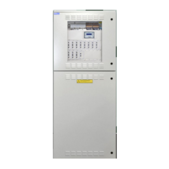
- Seite 1 Mounting- and Operating Instructions Montage- und Betriebsanleitung Central Battery System Zentralbatteriesystem CPS 220 / 20 / J-SV / J-SKÜ CPS 220 / 20 / J-SV / J-SKÜ CPS 220 / 64 / J-SV / J-SKÜ CPS 220 / 64 / J-SV / J-SKÜ TFT Touch controller TFT Touch Steuerteil Sicherheitstechnik GmbH...
-
Seite 3: Inhaltsverzeichnis
CPS 220/64/SV Mounting and Operating Instructions CPS 220/64/SV Montage- und Betriebsanleitung Inhalt Contents 1. General information 1. Allgemeine Hinweise 1.1. Symbolerklärung 1.1. Explanation of symbols 1.2. Liability and warranty 1.2. Haftung und Gewährleistung 1.3. Spare parts 1.3. Ersatzteile 1.4. Disposal 1.4. - Seite 4 CPS 220/64/SV Mounting and Operating Instructions CPS 220/64/SV Montage- und Betriebsanleitung 6.3. Elektrischer Anschluss 6.3. Electrical connection 6.3.1. Systemaufbau 6.3.1. System structure 6.3.2. CPS 220 / 20 …, CPS 220 / 64 …, CPUS 220 / 64 …, 6.3.2. CPS 220/20 …, CPS 220/64 …, CPUS 220/64 …, CPUSB 220 / 64 / 16, CPUSB 220 / 64 / 8 …...
- Seite 5 CPS 220/64/SV Mounting and Operating Instructions CPS 220/64/SV Montage- und Betriebsanleitung 7. Inbetriebnahme Commissioning 7.1. Überprüfung der Verbindungen 7.1. Checking the connections 7.2. Isolationsmessung 7.2. Insulation measuring 7.3. Einschalten des Zentralbatteriesystems 7.3. Energising the central battery system 7.4. De-energise the central battery system 7.4.
- Seite 6 Lüftersteuerung 8.6.5.6. Fan control 8.7. Programmierung 8.7. Programming 8.7.1. INOTEC Konfigurator 8.7.1. INOTEC Anlagen Konfigurator 8.7.2. Direktverbindung PC mit dem 8.7.2. Direct connection PC with TFT TFT Touch Steuerteil touch controller 8.7.2.1. Konfiguration des TFT Touch 8.7.2.1. Configuration of TFT...
- Seite 7 CPS 220/64/SV Mounting and Operating Instructions CPS 220/64/SV Montage- und Betriebsanleitung 10.3.1.3. SL mit SLÜ 10.3.1.3. SL with SLÜ 10.3.1.4. FS mit SLÜ 10.3.1.4. RS with SLÜ 10.3.2. Stromkreise programmieren 10.3.2. Program circuits 10.3.3. Leuchten programmieren 10.3.3. Program luminaires 10.3.3.1. Non-maintained li ghting (NM) 10.3.3.1.
-
Seite 8: Allgemeine Hinweise
1.4. Disposal Batteries and electronic components supplied by 1.4. Entsorgung INOTEC can be returned to INOTEC or should be disposed of in accordance with the national gui- Von INOTEC gelieferte Batterien und Elektronikbau- delines and regulations governing the disposal of teile können an INOTEC zurückgegeben werden... -
Seite 9: Sicherheitshinweise
INOTEC autorisierte Personen involve opening the device must ONLY be carried out by vorgenommen werden. Eingriffe durch andere Personen personnel authorised to do so by INOTEC. The guarantee führen zum Verlust der Gewährleistung. becomes invalid if unauthorised personnel work on the system. -
Seite 10: Produktbeschreibung
TFT Steuerteil. Die Programmierung des controller. The controller unit can be programmed with Gerätesteuerteils erfolgt über die komfortable INOTEC the comfortable “INOTEC Konfigurator” software. To trans- Konfigurator Software mittels USB Speichermedium oder fer the configuration a USB pen drive or LAN interface can direkter Verbindung über eine LAN-Schnittstelle. - Seite 11 CPS 220/64/SV Mounting and Operating Instructions CPS 220/64/SV Montage- und Betriebsanleitung sorgung erhalten. Manual tests for checking can be activated at any time. Automatic tests can also be run at freely programmable Jederzeit können manuelle Tests zur Überprüfung ausge- times. The test results and status changes are detailed in löst werden.
-
Seite 12: Aufbau Der Cps 220/20 Und Cps 220
CPS 220/64/SV Mounting and Operating Instructions CPS 220/64/SV Montage- und Betriebsanleitung • CPS 220 / 20 / 5,5kW / 3A, CPS 220 / 20 / 5,5kW / 7,5A • CPS 220/20/5.5 kW/3 A, CPS 220/20/5.5 kW/7.5 A Maximale Anschlussleistung 5,5kW mit 5 internen Maximum connected output 5.5 kW with 5 internal Modulplätzen für bis zu 20 Stromkreise und 16 externe module slots for up to 20 circuits and 16 external... - Seite 13 CPS 220/64/SV Mounting and Operating Instructions CPS 220/64/SV Montage- und Betriebsanleitung CPS 220 / 64 / 11kW CPS 220 / 64 / 11kW-2 Netzanschluß Mains Klemmen /Anschlußraum Terminals Sicherungsabgänge US Netz/ Batt Substation output CP 4x2A CP 4x2A CP 4x2A CP 4x2A CP 4x2A CP 4x2A...
- Seite 14 CPS 220/64/SV Mounting and Operating Instructions CPS 220/64/SV Montage- und Betriebsanleitung CPS 220 / 64 / 22kW- 3 phase Batteriesicherungen Battery fuses 850 008 850 009 Netzanschluß Mains CPS 220 / 64 / 11kW - 3 phase Anschlußklemmen Terminals CP 4x2A CP 4x2A CP 4x2A CP 4x2A...
-
Seite 15: Cpusb 220
CPS 220/64/SV Mounting and Operating Instructions CPS 220/64/SV Montage- und Betriebsanleitung Netzanschluß CPUS 220 / 64 / 11kW Mains Klemmen Anschlußraum Terminals Sicherungsabgänge US Netz/ Batt Substation output Stromkreismodule Circuit modules CP 4x2A CP 4x2A CP 4x2A CP 4x2A CP 4x2A CP 4x2A CP 4x2A CP 4x2A... -
Seite 16: Aufbau Der Cpusb - Systeme
= DL / M = DL / M = DL / M = DL / M = DL / M CPUSB 220 / 64 /1–2A CPUSB 220 / 64 /1–4A Klemmen Anschlußraum Terminals pot.frei SK2 SK3 SK4 Kontakte SL-SL+ Adresse INOTEC CPUSB 4x2A... -
Seite 17: Cpusb 220 / 64 / 1 - 2X2,5A/24V
TFT-Steuerteil nutzbar. can only be used with a TFT controller. Rettungs- und Sicherheitsleuchten mit INOTEC 24V- Emergency exit and safety luminaires with INOTEC 24V Technik und INOTEC 24V-D.E.R.-Leuchten für dynamische technology and INOTEC 24V-D.E.R. luminaires for dynamic Fluchtwegkennzeichnung können an die externe BUS-... -
Seite 18: Cpusb 220 / 64 / 24V
Spannung versorgt. Die Leuchtenbelegung und Ziel- configuration and destination programming is done ortprogrammierung erfolgt über das Steuerteil mittels via the central battery controller unit and the INOTEC INOTEC Konfigurator Software des Zentralbatteriegerätes, Konfigurator Software, which communicates with the BUS welches über die dreiadrige BUS-Leitung mit der BUS- sub station via the three-wire BUS data line. -
Seite 19: Technische Daten
3,15 A 3,15 A 3,15 A 3,15 A DPÜ / B.1 Adresse 1 bis 31 INOTEC 890 414 850 008 gem. VDE 0108 ta: -15 bis 40°C Kontakte (1 / 2) + (3 / 4) öffnen bei Netzausfall 3,15 A... - Seite 20 CPS 220/64/SV Mounting and Operating Instructions CPS 220/64/SV Montage- und Betriebsanleitung CPS 220 / 64 / 11kW CPS 220 / 64 / 22kW CPS 220 / 20 / 1,2A 3-phasig 3-phasig CPS 220 / 64 / 11kW 3phasig CPS 220 / 64 / 22kW 3phasig CPS 220 / 20 / 1,2A CP 4x2A CP 4x2A...
- Seite 21 CPS 220/64/SV Mounting and Operating Instructions CPS 220/64/SV Montage- und Betriebsanleitung CPS 220 / 20 / 5,5kW / 7,5A CPS 220 / 20 / 3A CPS 220 / 20 / 5,5kW / 3A CPS 220 / 20 / 3A CPS 220 / 20 / 3A CPS 220 / 20 / 5,5kW / 3A CPS 220 / 20 / 5,5kW / 3A Netz...
- Seite 22 CPS 220/64/SV Mounting and Operating Instructions CPS 220/64/SV Montage- und Betriebsanleitung CPUS 220 / 64 / 11kW CPUS 220 / 64 / 11kW CP 4x2A CP 4x2A CP 4x2A CP 4x2A CP 4x2A CP 4x2A CP 4x2A CP 4x2A 3,15 A 3,15 A 3,15 A 3,15 A...
-
Seite 23: Cpusb 220
CPS 220/64/SV Mounting and Operating Instructions CPS 220/64/SV Montage- und Betriebsanleitung 5.2. CPUSB 220 / 64 / 16, 5.2. CPUSB 220/64/16, CPUSB 220 / 64 / 8 – 1, CPUSB 220/64/8–1, CPUSB 220 / 64 / 8 – 9, CPUSB 220/64/8–9 CPUSB 220 / 64 / 1 - 2A, CPUSB 220/64/1–2A, CPUSB 220 / 64 / 1 –... -
Seite 24: Kabeleinführung Von Oben
CPS 220/64/SV Mounting and Operating Instructions CPS 220/64/SV Montage- und Betriebsanleitung 5.3. CPUSB 220 / 64 / 24V 5.3. CPUSB 220/64/24 V Schutzklasse: Protection class: Schutzart: IP 20 Protection category: IP 20 Zulässige Umgebungstemperatur: Permissible ambient temperature: für das Gerät: -5°C bis +35°C For the device: -5°C to +35°C... -
Seite 25: Aufstellung, Anschluss
CPS 220/64/SV Mounting and Operating Instructions CPS 220/64/SV Montage- und Betriebsanleitung 6. Aufstellung, Anschluss 6. Assembly, connection 6.1. Montage 6.1. Assembly Beachten Sie für die Lagerung der Komponenten For storage of the components until assembly, bis zur Montage die Hinweise in observe the information in ... -
Seite 26: Batterie
CPS 220/64/SV Mounting and Operating Instructions CPS 220/64/SV Montage- und Betriebsanleitung Jetzt kann die Haube des Gehäuses abgenommen wer- The cover can now be removed. The six screws and the den. Anschließend müssen die sechs Schrauben und die front cover now have to be removed so that the housing Frontabdeckung entfernt werden, um das Gehäuse an der can be fastened to the wall. -
Seite 27: Batterieschrank Mit 1 Strang Á 18 Blöcke
Bei Anschluß der Batterie ist auf die richtige connecting the battery! Polung zu achten! 6.2.1. 1 battery cabinet with 1 battery set, 6.2.1. 1 Batterieschrank mit 1 Strang 18 blocks each á 18 Blöcke Montage 12Ah Batterien F1 F2 INOTEC 708 146 Sicherheitstechnik GmbH, 59 469 Ense... -
Seite 28: Batterieschränke Mit 1 Strang
CPS 220/64/SV Mounting and Operating Instructions CPS 220/64/SV Montage- und Betriebsanleitung 6.2.2. 2 Batterieschränke mit 1 Strang 6.2.2. 2 battery cabinets with 1 battery set, á 18 Blöcke 18 blocks each F1 F2 6.2.3. 2 battery cabinets with 2 battery sets, 6.2.3. -
Seite 29: Batteriemontage Auf Batteriegestell
(CPUSB 220 / 64 …) um zusätzliche Endstromkreise stations (CPUSB 220/64 …). erweitert werden. Versorgungsleitung (L+ / N- / PE) Supply lead DPÜ gem. 0108 Batterieleitung (B+ / B-) INOTEC Battery cable CP 4x2A CP 4x2A CP 4x2A CP 4x2A CP 4x2A CP 4x2A CP 4x2A CP 4x2A Gerätebus (BUS+/ / +24V) -
Seite 30: Cpusb 220 / 64 / 16, Cpusb 220
CPS 220/64/SV Mounting and Operating Instructions CPS 220/64/SV Montage- und Betriebsanleitung Für den Betrieb der Unterstation CPUS 220 / 64 / … wird Operation of the sub station CPUS 220/64/… requires eine Netzzuleitung und eine Batterieleitung vom Haupt- a mains and a battery cable from the main device. Since gerät benötigt. -
Seite 31: Endstromkreise - X3
= DL / M 6.3.2.7. Final circuits CP24V 2x2,5A - X7 6.3.2.7. Endstromkreise CP 24V 2x2,5A - X7 Connect INOTEC 24V-LEDs to the terminals on INOTEC 24V-LED-Leuchten werden an die CP 24V 2x2,5A terminal rail X7 of the respective final circuit. -
Seite 32: Endstromkreise Cp D.e.r. - X14
6.3.2.8. Final circuits CP D.E.R. - X14 CP D.E.R. INOTEC 220V D.E.R. Leuchten werden an die Klemmen INOTEC 220V D.E.R. luminaires are connected to the termi- 2x2,5A L+, N-, B+, B- der Klemmleiste X14 angeschlossen. nals L+, N-, B+, B- on terminal rail X14. -
Seite 33: Stromkreisumschaltungen Cp 2X2,5A / 24V
This type of change-over device can be used in systems Dieser Typ Stromkreisumschaltung kann in den Anlagen CPS 220 / 20 and CPS 220 / 64 for INOTEC-emergency CPS 220 / 20 und CPS 220 / 64 für INOTEC-Notleuchten lights in the 24V or 24V D.E.R. versions. The circuit rack- mit 24V-Technik bzw. -
Seite 34: Stromkreisumschaltung Cp D.e.r. 2X2,5A
Die Stromkreisumschaltung CP D.E.R. 2x2,5A kann in den The change-over device CP D.E.R. 2x2,5A can be used Anlagen CPS 220/20 und CPS220/64 für INOTEC 220V in systems CPS 220/20 and CPS220/64 for INOTEC 220V D.E.R. Leuchten eingesetzt werden. D.E.R. luminaries. -
Seite 35: Cpusb 220 / 64 / 1
No output voltage spannung im in joker operation Jokerbetrieb Red (4 LEDs flashing Bus fault rot (blinken 4 LEDs Busstörung quickly) INOTEC CPUSB 4x2A schnell) Red (4 LEDs flashing Current loop open INOTEC CPUSB 4x2A rot (blinken 4 LEDs Stromschleife... -
Seite 36: Versorgungsspannung
CPS 220/64/SV Mounting and Operating Instructions CPS 220/64/SV Montage- und Betriebsanleitung Der maximale Einschaltstrom pro Stromkreis darf The maximum inrush current per circuit must not nicht mehr als 250A für 500µs betragen! exceed 250A for 500 µs! Für die Stromkreisumschaltungen nur Orginalsi- Use only original fuses with extinguishing agents cherungen mit Löschmitteln verwenden. -
Seite 37: Stromkreisweiche (Skw)
• Bei DC-Betrieb über die Versorgungsleitung der CPS: • With DC operation via the CPS supply lead: Grundsätzliche Versorgung der Notleuchten aus der CPS. Basic supply to emergency luminaires via the CPS. INOTEC CPUSB 4x2A 6.3.3.6. Adressierung 6.3.3.6. Addressing Den BUS-Unterstationen CPUSB 220 / 64 / 1 - … muss... -
Seite 38: Cpusb 220 / 64 / 24V
– – Stoer Bat.-B. Die Verkabelung erfolgt über die oberen Kabeleinführun- Cables are inserted from above. gen. INOTEC Ein/On Ein/On Ein/On Ein/On In the housing for surface-mounting the CPUSB Im Aufputzgehäuse der CPUSB 2220 / 64 / 24V ist 2220/64/24 V, cables can also be inserted from Betrieb auch eine rückseitige Kabeleinführung möglich. -
Seite 39: Gerätebus Ib2
ID for each circuit is connec- Im Fall der Nachinstallation ist darauf zu achten, dass ted to the CLS only once! jede Leuchten-ID pro Stromkreis nur einmal an der CLS angeschlossen wird! INOTEC 860 02 1 L-JET Leuchten-ID 56 381 ta: 50°C/U n :DC 24V±20%... -
Seite 40: Lichtschalterabfrage
DPÜ DPÜ gem. gem. gem. three-phase mo- 0108 0108 0108 überwachung nitor. Should the INOTEC INOTEC INOTEC anzuschließen. UVA 1 UVA 2 UVA 3 sub db 1 sub db 2 sub db 3 power fail, the 24 Bei Ausfall wird... -
Seite 41: Zentrales Dimmen
CPS 220/64/SV Mounting and Operating Instructions CPS 220/64/SV Montage- und Betriebsanleitung 6.3.4.6. Zentrales Dimmen 6.3.4.6. Central dimming Mit dem optionalen CLS- The optional CLS dimmer module oder Dimmer Modul können allows programmed luminaires in Potentiometer entsprechend programmierte the circuits to be dimmed centrally 0-10V Leuchten in den Stromkrei- sen über... - Seite 42 For temperature controlled charging, a sensor (type KTY Batterieraums an die Klemmen T+ / T- des RIF 5-Moduls or INOTEC sensor) must be connected inside the battery anzuschließen. Dieser muss zur temperaturgeführten compartment to terminals T+/T- of the RIF 5 module. This Ladung im Steuerteil aktiviert werden.
-
Seite 43: Betrieb
General lighting General lighting DPÜ DPÜ DPÜ gem. gem. gem. 0108 0108 0108 INOTEC INOTEC INOTEC UVA 1 UVA 2 UVA 3 Anschlüsse bei Überwachung ein- und dreiphasiger Netze Supply monitoring in single- and three-phase installation. SL- SL+ 850 009 RIF5... -
Seite 44: Emc Protection
SUB DB 2 SUB DB ... SUB DB 1 DPÜ / B.2 DPÜ / B.2 DPÜ / B.2 890 417 890 417 890 417 INOTEC INOTEC INOTEC 0 Min 5 Min 0 Min 5 Min 0 Min 5 Min Made in... -
Seite 45: Batteriemanagementsystem Bcs
CPS 220/64/SV Mounting and Operating Instructions CPS 220/64/SV Montage- und Betriebsanleitung 6.3.5.2. Batteriemanagementsystem BCS 6.3.5.2. Battery management system BCS Das Batteriemanagementsystem BCS ist nur mit The battery management system BCS can only be TFT-Steuerteil nutzbar. used with a TFT controller. Das Batteriemanagementsystem BCS besteht aus einer The battery management system consists of one control Kontrolleinheit und max. -
Seite 46: Bcs Sensor
CPS 220/64/SV Mounting and Operating Instructions CPS 220/64/SV Montage- und Betriebsanleitung Zustand Not- Zustand BCS- Reaktion Emerg. light device BCS sensor Reaction lichtgerät Sensor state state AC-Betrieb und Unterspannung Ladung wird aus- AC operation and Undervoltage Charging is swit- Ladung einge- geschaltet charging switched on ched off... - Seite 47 CPS 220/64/SV Mounting and Operating Instructions CPS 220/64/SV Montage- und Betriebsanleitung Durch drücken der unteren Taste (Enter-Taste ) erscheint Pressing the lower button (Enter button) calls up the das Menü des BCS-Moduls. Mittels der Pfeiltasten kann menu of the BCS module. The arrow buttons can be used durch das Menü...
- Seite 48 CPS 220/64/SV Mounting and Operating Instructions CPS 220/64/SV Montage- und Betriebsanleitung...
-
Seite 49: Lsa 3 / Lsa 8
CPS 220/64/SV Mounting and Operating Instructions CPS 220/64/SV Montage- und Betriebsanleitung 6.3.5.3. LSA 3 / LSA 8.1 6.3.5.3. LSA 3 / LSA 8.1 Mit den LSA 3- und LSA 8.1-Modulen ist ein gemeinsames With the LSA 3 and LSA 8.1 modules, the main and safety Ein- und Ausschalten von Netz- und Sicherheitsleuchten luminaires can be switched on and off together. -
Seite 50: Lsa
CPS 220/64/SV Mounting and Operating Instructions CPS 220/64/SV Montage- und Betriebsanleitung 6.3.5.3.2. LSA 8.1 6.3.5.3.2. LSA 8.1 Pro Steuerteil sind bis zu 3 LSA 8.1-Module an den Up to 3 LSA 8.1 modules can be connected to the device Gerätebus anschließbar. Die LSA 8.1 besitzt 8 galvanisch bus for each controller. - Seite 51 CPS 220/64/SV Mounting and Operating Instructions CPS 220/64/SV Montage- und Betriebsanleitung Zur Nutzung der integrierten DPÜ/B muss diese per Mi- To use the integrated DPÜ/B, this must be activated by croschalter am LSA 8.1-Modul aktiviert werden. microswitch on the LSA 8.1 module. Die eingestellte Adresse des LSA 8.1-Moduls ist The set address of the LSA 8.1 module is also the auch die Adresse für die DPÜ/B!
- Seite 52 CPS 220/64/SV Mounting and Operating Instructions CPS 220/64/SV Montage- und Betriebsanleitung UV 1 UV 2 DPÜ DPÜ gem. gem. 0108 0108 INOTEC INOTEC 24V– 24V– 24V– 24V– 24V– 24V– 24V– 24V– 850 007 LSA 8.1 230 V LSA 8.1 230V...
-
Seite 53: Dreiphasenüberwachungen
CPS 220/64/SV Mounting and Operating Instructions CPS 220/64/SV Montage- und Betriebsanleitung 6.3.5.4. Dreiphasenüberwachungen 6.3.5.4. Three-phase monitors (DPÜs) 6.3.5.4.1. DPÜ 6.3.5.4.1. DPÜs Zur Überwachung der Netzspannung an den Unter- To monitor the mains voltage at the general lighting sub- verteilern der Allgemeinbeleuchtung können die DPÜ- distribution boards, the DPÜ... -
Seite 54: Dpü/B
CPS 220/64/SV Mounting and Operating Instructions CPS 220/64/SV Montage- und Betriebsanleitung 6.3.5.4.2. DPÜ/B.2 6.3.5.4.2. DPÜ/B.2 Zur Überwachung der Netzspannung an den Untervertei- To monitor the mains voltage at the general lighting sub- lern der Allgemeinbeleuchtung werden die DPÜ/B.2- Mo- distribution boards, the DPÜ/B.2 modules are integrated dule direkt in den Unterverteiler eingebaut. - Seite 55 Nom.-frequency: 50/60 Hz Nennfrequenz: 50/60 Hz Activation level: 0,85 U Ansprechwert: 0,85 U Bus connection: INOTEC internal system BUS Busanschluss: INOTEC interner Gerätebus CPS 220/64, CPS 220/20 und CPS 220/64, CPS 220/20 und CPS 220/48.1 CPS 220/48.1 Adress range: 1 ... 31 Adressbereich: 1 ...
-
Seite 56: Dpü/B
CPS 220/64/SV Mounting and Operating Instructions CPS 220/64/SV Montage- und Betriebsanleitung 6.3.5.4.3. DPÜ/B.1 6.3.5.4.3. DPÜ/B.1 Zur Überwachung der Netzspannung an den Untervertei- To monitor the mains voltage at the general lighting sub- lern der Allgemeinbeleuchtung werden die DPÜ/B.1- Mo- distribution boards, the DPÜ/B.1 modules are integrated dule direkt in den Unterverteiler eingebaut. -
Seite 57: Kontaktbestückung: 2 Schließer / Kontakt
50/60 Hz Rated frequency: 50/60 Hz Ansprechwert: 0,85 U Response value: 0.85 U Busanschluss: INOTEC interner Gerätebus Bus connection: INOTEC internal device bus Adressbereich: Address range: 1 . . . 31 1–31 Ausgang Output Kontaktbestückung: 2 Schließer Contacts 2 NO-contacts / Kontakt: 30 V DC, 1 A... -
Seite 58: Lomo
Zener diode Zener diode DPÜ DPÜ DPÜ DPÜ DPÜ DPÜ DPÜ DPÜ DPÜ SL - SL - SL - INOTEC INOTEC INOTEC 850 009 850 009 LOMO LOMO LOMO 850 014 850 014 850 014 24 V. 24 V. 24 V. -
Seite 59: Remote Mimic Panel - Mtb
CPS 220/64/SV Mounting and Operating Instructions CPS 220/64/SV Montage- und Betriebsanleitung 6.3.5.6. Fernmeldetableau – MTB 6.3.5.6. Remote mimic panel — MTB Das Fernmeldetableau wird an das RIF5-Modul gem. The remote mimic panel is connected to the RIF5 module nachfolgendem Schaltbild angeschlossen. Die Leitungs- in accordance with the circuit diagram below. -
Seite 60: Cps-Mtb
= BL / NM = DL / M = BL / NM = DL / M = BL / NM = DL / M = BL / NM = DL / M schnitt) 500m. INOTEC INOTEC INOTEC Störung Betrieb Betrieb Betrieb Failure Batt.-Betrieb Batt.-Betrieb... -
Seite 61: Inoweb
CPS 220/64/SV Mounting and Operating Instructions CPS 220/64/SV Montage- und Betriebsanleitung 6.3.5.8. INOWEB 6.3.5.8. INOWEB Über das im TFT Steuerteil integriert INOWEB-Modul The INOWEB (integrated in TFT controller unit) module kann der Zustand des CPS-Gerätes mittels Netzwerkver- enables the status of the CPS device to be polled via the bindung abgefragt werden. -
Seite 62: Inbetriebnahme
Die Isolationsmessung nicht an Stromkreisen mit Do not perform the insulation measurement on INOTEC 24V-Leuchten durchführen. Die Leuchten the circuits with INOTEC 24V luminaires. This would werden zerstört. destroy the luminaires. Die Isolationsmessung ist mit einer max. Messspannung The insulation must be measured with a max. -
Seite 63: Einschalten Des Zentralbatteriesystems
CPS 220/64/SV Mounting and Operating Instructions CPS 220/64/SV Montage- und Betriebsanleitung To protect active components from being Um aktive Bauteile destroyed during the Endstromkreis 1.2 vor eventueller measurement, L and N must Zerstörung durch be connected! die Messung zu schützen, sind L und N miteinander Endstromkreis 1.1 The battery circuit is zu verbinden! -
Seite 64: Tft Steuerteil Touchdisplay
Favoriten oder ein Hilfemenü aufgerufen werden können. A reset-button, for performing a restart of the controller, is located between the INOTEC logo and the USB interface. Markiert werden Menüs, Funktionen und Einstellungen durch Berühren der jeweiligen Schaltfläche. Hierbei wird das aktivierte Feld hellblau hinterlegt. -
Seite 65: Begrifflichkeiten
CPS 220/64/SV Mounting and Operating Instructions CPS 220/64/SV Montage- und Betriebsanleitung 8.2. Begrifflichkeiten 8.2. Concepts 8.2.1. Symbole Gerätestatus 8.2.1. System status icons Der Status des Gerätes wird durch entsprechende Sym- The system’s status is indicated by symbols and colours bole und Farben in der Menüführung dargestellt. Zuord- within the menu navigation. -
Seite 66: Symbole Steuerteil
CPS 220/64/SV Mounting and Operating Instructions CPS 220/64/SV Montage- und Betriebsanleitung 8.2.2. Symbole Steuerteil 8.2.2. Controller icons Handrückschaltung quittieren Funktionstest Confirm manual reset Function test Batteriedauertest Funktionen Battery duration test Functions Batteriedauertest abbrechen Cancel battery duration test Batteriedauertest starten Ladung einschalten Start battery duration test Start charging Geräteeinstellungen... -
Seite 67: Symbolbeschreibung Komponenten
CPS 220/64/SV Montage- und Betriebsanleitung 8.2.3. Symbolbeschreibung Komponenten 8.2.3. Explanation of components icons Bus: BUS: Interner Gerätebus zum Anschluss von Internal device BUS for connecting INOTEC INOTEC Modulen (Stromkreise, LSA, DPÜ/B, modules (change over devices, LSA, DPÜ/B, etc.) etc.) Stromkreiseinschub:... -
Seite 68: Symbolbeschreibung Untere Menü Leiste
CPS 220/64/SV Mounting and Operating Instructions CPS 220/64/SV Montage- und Betriebsanleitung 8.2.4. Symbolbeschreibung untere Menü leiste 8.2.4. Explanation menu bar icons Menü Menu Über diese Schaltfläche gelangen Sie in This button enables access to the main eine Menüauswahl, in dem übergeord- menu. -
Seite 69: Bedienung
8.3. Bedienung 8.3. Operation Die Navigation der Software des INOTEC TFT Touch- You can navigate through the software of the INOTEC TFT displays führt Sie durch Menüs, die Sie per Fingerdruck touch controller by touching on the given icons. einzelner Symbole aufrufen können. -
Seite 70: Statusanzeige
In der Mitte befindet sich das Tagesda- shown here. Current date and time are displayed in the tum mit aktueller Uhrzeit. Rechts ist das Firmenlogo von middle. The INOTEC company logo is illustrated on the INOTEC abgebildet. right. -
Seite 71: Leuchten
CPS 220/64/SV Mounting and Operating Instructions CPS 220/64/SV Montage- und Betriebsanleitung 8.4.4.1. Leuchten 8.4.4.1. Luminaires Durch Auswahl der Leuchtenschaltfläche gelangen Sie Selecting the luminaire button guides you to the BUS le- in die BUS-Ebene. Hier lassen sich Informationen der vel. Information about the activated changeover devices angemeldeten Stromkreiseinschübe, sowie den zugehöri- and the associated final circuits can be found here. -
Seite 72: Menü Stromkreiseinschübe
CPS 220/64/SV Mounting and Operating Instructions CPS 220/64/SV Montage- und Betriebsanleitung fehlerhafte Kommunikation zwischen dem Einschub und the SKU and the slot, for instance. dem Slot hervorgerufen werden kann. If a final circuit has a failure, it is Sofern ein Endstromkreis mit einer fully highlighted in red. -
Seite 73: Menü Endstromkreise
CPS 220/64/SV Mounting and Operating Instructions CPS 220/64/SV Montage- und Betriebsanleitung sowie Art des Einschubes sind rechts neben dem Symbol found on the right, next to the changeover device icon. des Stromkreiseinschubes zu erkennen. Die Stromkreise The circuits of the SKUs are arranged horizontally on the befinden sich den Einschüben untergeordnet, in waage- right of the menu. -
Seite 74: Detailansicht Endstromkreis
CPS 220/64/SV Mounting and Operating Instructions CPS 220/64/SV Montage- und Betriebsanleitung 8.4.4.1.4. Detailansicht Endstromkreis 8.4.4.1.4. Final circuit detailed view Durch Anwählen des Endstromkreissymbols gelangen Sie You can reach the sub-menu of the final circuit by acti- vating the final circuit icon. in das Untermenü... -
Seite 75: Menü Leuchten
CPS 220/64/SV Mounting and Operating Instructions CPS 220/64/SV Montage- und Betriebsanleitung 8.4.4.1.5. Menü Leuchten 8.4.4.1.5. Luminaire menu Sofern ein Zielort vergeben wurde, ist dieser in der jewei- A destination text is shown on the respective luminaire ligen Leuchtenschaltfläche zu erkennen. Sofern mehrere button, if entered. -
Seite 76: Batterie
CPS 220/64/SV Mounting and Operating Instructions CPS 220/64/SV Montage- und Betriebsanleitung 8.4.4.1.7. Detailansicht Leuchten (24V) 8.4.4.1.7. Detailed view of luminaires (24V) Bei 24V Leuchten ist die individuelle sowie die frei pro- In case of 24V luminaires, the individual address and the grammierbare Adresse der Leuchte den beiden oberen freely programmable address can be found in the two Sichtfenstern zu entnehmen. -
Seite 77: Batterie
8.4.4.2.2. BCS: This menu is only available if the battery blocks are moni- Sofern die Batterieblöcke des Notlichtgerätes mit dem tored by the INOTEC BCS system. INOTEC BCS-System überwacht werden, steht dieser All data from the “sensors 1–18” and/or “sensors 19–36”... -
Seite 78: Shunt
CPS 220/64/SV Mounting and Operating Instructions CPS 220/64/SV Montage- und Betriebsanleitung Jeder Sensor ist in einer separaten Tabellenspalte mit Each sensor is displayed in a separate column, showing aktuellen Werten des zu überwachenden Batterieblocks the current values of the monitored battery block. The dargestellt. -
Seite 79: Komponenten
CPS 220/64/SV Mounting and Operating Instructions CPS 220/64/SV Montage- und Betriebsanleitung 8.4.4.3. Komponenten 8.4.4.3. Components Durch Auswahl dieser Schaltfläche werden menügeführt More detailed information about activated components detaillierte Informationen im Bereich angemeldeter Kom- (SLÜ, RIF, LSA8, LSA 3 or DPÜ/B) are shown after selecting ponenten (SLÜ, RIF, LSA 8, LSA 3 oder DPÜ/B) dargestellt. -
Seite 80: Fernschalter
CPS 220/64/SV Mounting and Operating Instructions CPS 220/64/SV Montage- und Betriebsanleitung Fernschalter: Remote switch: Dieses Menü dient zur Anzeige der in der Programmie- This menu indicates the setting, which was done in the rung erfolgten Einstellungen. programming. Fernschalter aktiviert Remote switch activated Fernschalter deaktiviert Remote switch deactivated Stromschleife:... -
Seite 81: Lsa8 / Lsa 3 Menu
CPS 220/64/SV Mounting and Operating Instructions CPS 220/64/SV Montage- und Betriebsanleitung Den Optionskontakten 4 und 5 können verschiedene Various messages can be assigned to the optional con- Meldungsarten zugewiesen werden. Kontakte, die in den tacts 4 and 5. Contacts that can be configured by these Meldungen variabel konfiguriert werden können, sind mit messages are indicated with a dotted line below the einer gestrichelten Linie unterhalb der jeweiligen Kon-... - Seite 82 CPS 220/64/SV Mounting and Operating Instructions CPS 220/64/SV Montage- und Betriebsanleitung Mit den LSA8- und LSA 3-Modulen ist ein gemeinsames The LSA8 and LSA 3 modules can be used to switch the Ein- und Ausschalten von Netz- und Sicherheitsleuchten general- and emergency luminaires simultaneously on möglich.
-
Seite 83: Dpü/B Menu
CPS 220/64/SV Mounting and Operating Instructions CPS 220/64/SV Montage- und Betriebsanleitung 8.4.4.3.4. Menü DPÜ/B 8.4.4.3.4. DPÜ/B menu Durch Betätigen des Symbols DPÜ/B öffnet Activating the DPÜ/B icon opens the corres- sich der entsprechende Dialog. ponding dialogue window. Zur Überwachung der Netzspannung an den Untervertei- The DPÜ/B modules are directly installed into the sub- lern der Allgemeinbeleuchtung werden die DPÜ/B-Modu- distribution boards to monitor the supply voltage of the... -
Seite 84: Menü
CPS 220/64/SV Mounting and Operating Instructions CPS 220/64/SV Montage- und Betriebsanleitung 8.5. Menüleiste 8.5. Menu bar Die Navigationsleiste befindet sich im unteren Bereich The menu bar is located at the bottom of the main des Hauptmenüs. In diesem Bereich ist es möglich, menu. -
Seite 85: Isolationstesteinrichtung Prüfen (Iso Test)
CPS 220/64/SV Mounting and Operating Instructions CPS 220/64/SV Montage- und Betriebsanleitung 8.6.1.1. Funktionstest (FT) starten 8.6.1.1. Start function test (FT) Durch Betätigen der Schaltfläche wird ein Funktions- A function test is activated by pressing the button test aktiviert. In FT mode, the device switches to battery operation and Im Funktionstestmodus schaltet das Gerät in den Bat- checks the operability of the connected and activated teriebetrieb und überprüft die angeschlossenen und... -
Seite 86: Tiefentladeschutz Testen
CPS 220/64/SV Mounting and Operating Instructions CPS 220/64/SV Montage- und Betriebsanleitung 8.6.1.3. Betriebsdauertest (BT Test) 8.6.1.3. Battery duration test (DT) Durch Betätigen der Schaltfläche wird ein Batte- A battery duration test is activated by pressing the riedauertest gestartet. Der Batteriedauertest schaltet das button. -
Seite 87: Funktionen
Tiefentladeschutz zu quittieren. scharge protection. If the device includes an INOTEC BCS Sofern dem Gerät ein INOTEC BCS System angebunden system and the charging has been switched off, you can wurde, kann in diesem Menü... -
Seite 88: Handrückschaltung Quittieren
CPS 220/64/SV Mounting and Operating Instructions CPS 220/64/SV Montage- und Betriebsanleitung 8.6.2.3. Handrückschaltung quittieren 8.6.2.3. Confirm manual reset Bei aktivierter Handrückschaltung erfolgt nach einem If the manual reset is activated, the device will stay in Netzausfall die Rückschaltung erst durch eine manuelle battery operation until a manual confirmation was done Bestätigung am Gerät oder per Fernüberwachung. -
Seite 89: Störungsinfo
CPS 220/64/SV Mounting and Operating Instructions CPS 220/64/SV Montage- und Betriebsanleitung 8.6.3.1. Störungsinfo 8.6.3.1. Failure info In diesem Menü werden die aktuell vorliegenden Störun- This menu shows all currently existing failures. Device gen angezeigt. Zuerst werden vorhandene Gerätestö- failures are displayed at first, circuit/luminaire failures rungen dargestellt, anschließend die ersten fehlerhaften afterwards. -
Seite 90: Bcs Prüfbuch Ansehen
CPS 220/64/SV Mounting and Operating Instructions CPS 220/64/SV Montage- und Betriebsanleitung 8.6.3.4. BCS Prüfbuch ansehen 8.6.3.4. Show BCS logbook Im Prüfbuch zum BCS -System werden Zustandänderun- The logbook of the BCS logs status changes of the battery gen des Battriemanagementsystems und einmal täglich management system, as well as the battery block values die Batterieblockwerte protokolliert. -
Seite 91: Usb
Steuerteil ausgelesen und 8.6.4.1. Directory structure USB Stick abgespeichert werden. In order to guarantee a secure data transfer of an INOTEC controller unit and the respective configurator software 8.6.4.1. Verzeichnisstruktur USB Stick the directory structure of the USB- stick is predefined and Um die verschiedenen Dateiformate jeweiliger Anwen- can‘t be changed. - Seite 92 CPS 220/64/SV Mounting and Operating Instructions CPS 220/64/SV Montage- und Betriebsanleitung CONF_RD CONF_RD Zum Lesen der Konfigurationsdateien vom Speichermedi- Read config files (INO- / USB- Stick to controller unit) um in das Steuerteil. CONF_WR CONF_WR Write / save configuration files Zum Schreiben/Sichern von Konfigurationsdateien.
-
Seite 93: Konfiguration Laden
8.6.4.2. Konfiguration laden 8.6.4.2. Load configuration Eine Konfiguration, welche mit der optionalen INOTEC A configuration, which was created by the INOTEC Konfi- Konfigurator Software erstellt wurde, kann über die gurator software, can be loaded into the central battery Schaltfläche „Konfiguration laden“ von dem USB Speicher- system from a USB flash memory by the button “Load... - Seite 94 CPS 220/64/SV Mounting and Operating Instructions CPS 220/64/SV Montage- und Betriebsanleitung Durch Betätigen der Schaltfläche wird der Name Activating the button will save the entered file gespeichert und erscheint als Dateiname im überge- name. Using the button will cancel the entry. ordnetem Menü.
-
Seite 95: Prüfbuch / Bcs Prüfbuch Speichern
The saved file can be found in the folder “CONF_WR” on dem USB-Speichermedium gespeichert und kann mit der the USB flash memory. You can edit / print the file by the optionalen INOTEC Konfigurationssoftware bearbeitet INOTEC Konfigurator software. und ausgedruckt werden. -
Seite 96: Einstellungen
CPS 220/64/SV Mounting and Operating Instructions CPS 220/64/SV Montage- und Betriebsanleitung Durch Auswahl dieser Datei werden die Daten geladen roller. An automatic reboot will load the new software. und das Steuerteil bootet mit der neuen Software. Please get in contact with us before you perform Eine Aktualisierung der Steuerteilsoftware sollte any update. -
Seite 97: Netzwerk
CPS 220/64/SV Mounting and Operating Instructions CPS 220/64/SV Montage- und Betriebsanleitung 8.6.5.1. Gerät 8.6.5.1. Device In diesem Menü können Einstellungen einzelner Bereiche Device settings can be modified in this menu. The settings (Gerätetyp, Zielort, Blockierung, Umschaltzeit, Watchdog include: device type, destination text, blocking, changeo- oder Handrückschaltung) des Gerätes vorgenommen ver time, Watchdog and manual reset. -
Seite 98: Uhrzeit + Datum
CPS 220/64/SV Mounting and Operating Instructions CPS 220/64/SV Montage- und Betriebsanleitung Dazu sind folgende Informationen vom Netzwerkadmi- The following information is required from the network nistrator notwendig: administrator: ==> IP Adresse ==> IP adress ==> Subnetzmask ==> Subnet mask ==> Gateway ==>... - Seite 99 CPS 220/64/SV Mounting and Operating Instructions CPS 220/64/SV Montage- und Betriebsanleitung In der oberen Zeile des Dialoges ist das gewählte Tages- The upper line of the dialogue window displays the cho- datum sichtbar. In der Mitte ist ein Kalender mit einzelnen sen date.
-
Seite 100: Sprache
CPS 220/64/SV Mounting and Operating Instructions CPS 220/64/SV Montage- und Betriebsanleitung 8.6.5.4. Sprache 8.6.5.4. Language Im Sprachmenü kann zwischen verschiedener Landes- The language menu offers a choice of different languages. sprachen ausgewählt werden. The following languages are available: Folgende Sprachen sind für das Steuerteil auswählbar: •... - Seite 101 CPS 220/64/SV Mounting and Operating Instructions CPS 220/64/SV Montage- und Betriebsanleitung SKÜ Stromkreise SKÜ circuits Für Stromkreise mit der Überwachungsart Stromkreis- A Learn Mode has to be carried out for final circuits in überwachung muss ein Learnmode ausgeführt werden, circuit-monitoring mode. This is needed to detect the um die Stromaufnahme der angeschlossenen Verbrau- current consumption of the connected luminaires.
-
Seite 102: Lüftersteuerung
Download zu erhalten. You can download the INOTEC Konfigurator software for 8.7.1. INOTEC Anlagen Konfigurator free of charge from the INOTEC website. Just open your web browser and enter the link Die INOTEC Konfigurationssoftware ist kostenfrei als „inotec-licht.de/konfigurator.html“. -
Seite 103: Direktverbindung Pc Mit Dem Tft Touch Steuerteil
CPS 220/64/SV Mounting and Operating Instructions CPS 220/64/SV Montage- und Betriebsanleitung Detaillierte Informationen zur Anwendung der INOTEC Detailed information about how to use the INOTEC Kon- Konfigurationssoftware finden Sie in der Bedienungsan- figurator software can be found in the operating instruc- leitung (Artikel-Nr.: 708123). -
Seite 104: Konfiguration Des Pc Für Windows
CPS 220/64/SV Mounting and Operating Instructions CPS 220/64/SV Montage- und Betriebsanleitung Um eine direkte Verbindung in einem Netzwerk zwischen A direct communication with a network is only working den Komponenten herzustellen, muss DHCP deaktiviert when the DHCP function has been deactivated. The IP und die IP Adresse manuell konfiguriert werden. - Seite 105 CPS 220/64/SV Mounting and Operating Instructions CPS 220/64/SV Montage- und Betriebsanleitung In diesem Menü ist das Element „Internetprotokoll Version Activate the element “Internet protocol version 4(TCP/ 4 (TCP/IPv4)“ mit der Maustaste zu markieren. IPv4)” by mouse click. Die Schaltfläche „Eigenschaften“ ist dadurch aktiv und führt durch betätigen in das Untermenü...
-
Seite 106: Return Button
CPS 220/64/SV Mounting and Operating Instructions CPS 220/64/SV Montage- und Betriebsanleitung Der Wert für die Subnetzmaske ist mit 255.255.255.0 zu The subnet mask has to be 255.255.255.0. The network definieren. Durch bestätigen mit „OK“ wird die Netzwerk- configuration will be saved by clicking on “OK”. konfiguration gespeichert. -
Seite 107: Inoweb
CPS 220/64/SV Mounting and Operating Instructions CPS 220/64/SV Montage- und Betriebsanleitung 9. INOWEB 9. INOWEB Über die INOWEB-Schnittstelle können die Statusinforma- The status information of the luminaires can be displayed tionen zur Leuchte mittels eines Webbrowser dargestellt via the INOWEB interface using a web browser. To that werden. -
Seite 108: Störungsausdruck
CPS 220/64/SV Mounting and Operating Instructions CPS 220/64/SV Montage- und Betriebsanleitung The destinations are shown in the current display, which Die Zielorte werden in der Stromkreisdarstellung ange- can be shown by clicking the luminaires. zeigt, die mit einem Mausklick auf die Leuchten aufgeru- fen wird. -
Seite 109: Externe Verknüpfungen
Für die Stromkreise am IB 2 ist folgende Adresse http://<IP adress_TFT-controller>/cgi-bin/cgi_ einzugeben: inoweb?text=X_2 http://<IP-Adresse_TFT-Steuerteil>/cgi-bin/cgi_ inoweb?text=X_2 Externer Link des Gerätes http://www.inotec-licht.de Externer Link des Gerätes http://www.inotec-licht.de Ext. Link Platz 01: circuit 01 http://www.inotec-licht.de/erdgeschoss.pdf Ext. Link Platz 01: Stromkreis 01 http://www.inotec-licht.de/erdgeschoss.pdf Ext. Link Platz 01: circuit 02 http://www.google.de... - Seite 110 CPS 220/64/SV Mounting and Operating Instructions CPS 220/64/SV Montage- und Betriebsanleitung A green check mark next to the Apache indicates that the Ein grüner Haken neben dem Feld Apache deutet an, dass server was started. der Webserver gestartet wurde. Starting behaviour and the TCP-port can be configured Unter „Settings“...
-
Seite 111: Inoweb E-Mail Setup
CPS 220/64/SV Mounting and Operating Instructions CPS 220/64/SV Montage- und Betriebsanleitung 9.3.2. INOWeb E-Mail Setup 9.3.2. INOWeb E-Mail Setup Mittels INOWeb E-Mail Client hat der Anwender die Mög- The INOWeb E-Mail Client enables the possibility to lichkeit über geschehene Ereignisse der Anlage per E-Mail inform the user about all events, which happened to the informiert zu werden. - Seite 112 CPS 220/64/SV Mounting and Operating Instructions CPS 220/64/SV Montage- und Betriebsanleitung Über dieses Menü stehen dem Anwender folgende Funk- This menu offers the following functions: tionen zur Verfügung: Project: Hier ist die Vergabe der Projektebe- Projekt: Hier ist die Vergabe der Projekt- zeichnung möglich.
- Seite 113 CPS 220/64/SV Mounting and Operating Instructions CPS 220/64/SV Montage- und Betriebsanleitung Aktuelle Hier ist die Senderadresse hinterlegt. E-Mail sender Enter the e-mail address of the sender Sender E-Mail adress: here. Adresse: E-Mail recipi- You can enter up to two recipients here. Aktuelle Emp- ent Adress: An dieser Position können bis zu zwei...
-
Seite 114: Programmierung Cpusb 220/64
CPS 220/64/SV Mounting and Operating Instructions CPS 220/64/SV Montage- und Betriebsanleitung 10. Programmierung CPUSB 220/64/24 10. Programming CPUSB 220/64/24 10.1. Bedienung und Menüstruktur 10.1. Operation and menu structure C P U S B 2 4 V C P U S B 2 4 V B e t r i e b O p e r a t i o n... -
Seite 115: Testmenü
CPS 220/64/SV Mounting and Operating Instructions CPS 220/64/SV Montage- und Betriebsanleitung Das Hauptmenü wird durch Drücken der Taste „OK“ auf- The main menu is opened by clicking "OK". gerufen. 1. Test menu 1. Testmenü 1.1. FT start 1.1. FT-Start 2. Programming 1.2. -
Seite 116: Rs With Slü
CPS 220/64/SV Mounting and Operating Instructions CPS 220/64/SV Montage- und Betriebsanleitung 10.4.1. Geräteeinstellungen 10.4.1. Program device OK Programmierung OK Geräteprog. OK OK Programming OK Device prog. OK U n t e r s t a t i o n S u b s t a t i o n R e l a i s P r o g . -
Seite 117: Stromkreise Programmieren
CPS 220/64/SV Mounting and Operating Instructions CPS 220/64/SV Montage- und Betriebsanleitung - Netzausfall HV - Main-db failure - Netzausfall UV - Sub-db failure - Starkladung - Boost charging - Ladestörung - Charging failure - Gerät blockiert - Device blocked 10.4.1.3. SL with SLÜ 10.4.1.3. -
Seite 118: Bereitschaftslicht (Bl)
CPS 220/64/SV Mounting and Operating Instructions CPS 220/64/SV Montage- und Betriebsanleitung L e u c h t e : S K : 1 L u m . : C I : 1 Z u m u n d a b m e l d e n p r e s s d r ü... -
Seite 119: Spracheinstellung
CPS 220/64/SV Mounting and Operating Instructions CPS 220/64/SV Montage- und Betriebsanleitung „inv“ wird der Eingang invertiert, die Zuweisung wird bei using the “inv” option and the assignment is activated Öffnung des Kanals aktiviert. when the channel is opened. 10.4.3.4. Zentrales Dimmen (Dim) 10.4.3.4. -
Seite 120: Störungsinformationen
CPS 220/64/SV Mounting and Operating Instructions CPS 220/64/SV Montage- und Betriebsanleitung 10.5.2. Stromkreisinformation / 10.5.2. CI/Lum info Leuchteninformation OK Info OK SK/Luminaire info OK Display of the occupied circuits with destinations. Clicking OK Info OK SK/Leuchteninfo OK “OK”... -
Seite 121: Tägliche Prüfungen
CPS 220/64/SV Mounting and Operating Instructions CPS 220/64/SV Montage- und Betriebsanleitung zur erneuten Wiederaufladung nicht Ihre volle Leistungs- at full capacity until it is recharged and there is a risk of kapazität besitzt und die Gefahr eines Ausfall der Strom- power failure, which is why longer tests must only be versorgung besteht, sind Prüfungen von längerer Dauer carried out at times of low risk and must comply with... -
Seite 122: 3-Jährige Prüfungen
CPS 220/64/SV Mounting and Operating Instructions CPS 220/64/SV Montage- und Betriebsanleitung Die Versorgung der allgemeinen Beleuchtung muss clean and fully functional. wieder hergestellt werden und die Ladeeinrichtung ist auf The general lighting supply must be re-established and einwandfreie Funktion zu überprüfen. the charging equipment checked to ensure it is working correctly. -
Seite 123: Anhang
CPS 220/64/SV Mounting and Operating Instructions CPS 220/64/SV Montage- und Betriebsanleitung Anhang Appendix A. Dokumentation A. Documentation Die beiliegende Dokumentations-CD enthält von den The enclosed documentation CD contains the following Standard CPS 220 / 64-Geräten folgende Informationen: information on the standard CPS 220/64 devices: •... -
Seite 124: Kundendienst
CPS 220/64/SV Mounting and Operating Instructions CPS 220/64/SV Montage- und Betriebsanleitung C. Kundendienst C. Customer Service Bevor Sie den Kundendienst aufgrund einer vorliegenden Before contacting the customer service due to a failure, Störung kontaktieren, überprüfen Sie bitte Folgendes: please check the following: Prüfung auf Leuchtenfehler Check for luminaire failures Betätigen Sie in der Navigationsleiste den Menübutton, es... -
Seite 125: Softwarestand
• Device type and device number (KA…) on the type plate tung finden Sie unter dem Menüpunkt „Kontakt“ auf • A brief description of the failure www.inotec-licht.de). • Plain text information in the controller Bitte geben die folgenden Informationen an: We recommend the agreement of an inspection •... -
Seite 126: Index
CPS 220/64/SV Mounting and Operating Instructions CPS 220/64/SV Montage- und Betriebsanleitung Index Index Anschluss Assembly Anschlussklemmen 31,33 Battery 26,122 Batterie 67,70,76,77,80,86,88 Battery cabinets 26,28 Batterieinspektion Battery duration test 45,46,65,66,86,100,107,120,121 Batterieschränke 26,28 Battery inspection Batterietemperatur Battery monitoring Batterieüberwachung Battery temperature 27,66,67,76,77,78,80,87,88,90,91 27,66,67,76,77,78,80,87,88,90,91 BCS Prüfbuch 66,77,90... - Seite 127 CPS 220/64/SV Mounting and Operating Instructions CPS 220/64/SV Montage- und Betriebsanleitung Handrückschaltung 65,66,87,88,97,107 Function buttons 69,70 Hilfetexte Function test 8,107,121,124 71,82 Help texts 71,82,83 Inbetriebnahme 9,62 71,82 Info 68,84,88 71,82,83 Geräte Individual luminaire monitoring 10,33,100 Leuchten Info 68,84,88 Störung Circuit Informationsbereich 69,70 Device...
- Seite 128 CPS 220/64/SV Mounting and Operating Instructions CPS 220/64/SV Montage- und Betriebsanleitung Reparaturen Release 66,87 67,79,80,102 Remote switch 43,47,67,79,87,116,120 RIF 5 41,45,46,59 Repairs 30,60,123 67,79,80,102 RIF 5 41,45,46,59 30,60,123 Scrollen 68,84,89,106 Shunt 76,78 Sicherheitshinweise Safety instructions SKÜ 100,101 Scroll 68,106 SL+/SL- 36,40,43 Shunt 76,78...
-
Seite 129: Glossar
CPS 220/64/SV Mounting and Operating Instructions CPS 220/64/SV Montage- und Betriebsanleitung Glossar Battery control system Monitoring and logging of battery block voltage(s) and -temptature(s) measured by Batteriemanagmentsystem BCS-sensor(s) Erfassung und Protokollierung der Batterie blockspannung und -temperatur Battery control system mittels BCS-Sensor. BCS-Sensor Voltage- / temperature- measurement Batteriemanagmentsystem... - Seite 130 CPS 220/64/SV Mounting and Operating Instructions CPS 220/64/SV Montage- und Betriebsanleitung CPUSB BUS-Unterstation ohne eigenes Steuerteil Circuit separating module (SKW) zum Betrieb am Steuerteil einer CPS Power supply for the circuit comes from oder CPUS. the local sub-distribution board during Dauerlicht Eine Notleuchte/Stromkreis im Zustand standard operation.
- Seite 131 TEC controllers, used for printing out data genrelevanter Daten sowie Einspielen von relevant to systems. Softwareupdates. INOSTICK Adapter for PS/2 interfaces on INOTEC con- INOWEB Ethernetmodul mit integriertem Webser- trollers for importing and exporting system ver. Ermöglicht den Zugriff auf den Anla- confi gurations, printing out data relevant genstatus per Webbrowser.
- Seite 132 CPS 220/64/SV Mounting and Operating Instructions CPS 220/64/SV Montage- und Betriebsanleitung Nennbetriebsdauer Loop monitoring Die laut den gültigen Vorschriften notwen- System for monitoring an SL+/SL- or dige Betriebsdauer des Notlichtgerätes im FS+/FS- for open circuits or short circuits Notbetrieb.
- Seite 133 CPS 220/64/SV Mounting and Operating Instructions CPS 220/64/SV Montage- und Betriebsanleitung RTG-BUS BUS-System von INOTEC zur Überwa- RTG-BUS BUS system from INOTEC for monitoring the chung der Notlichtgeräte mittels weiterer emergency lighting device using other INO- INOTEC-Systeme oder Software. TEC systems or software.
- Seite 134 CPS 220/64/SV Mounting and Operating Instructions CPS 220/64/SV Montage- und Betriebsanleitung INOTEC Sicherheitstechnik GmbH Am Buschgarten 17 D - 59 469 Ense Tel +49 29 38/97 30- 0 Fax +49 29 38/97 30-29 Technische Änderungen vorbehalten! www.inotec-licht.de Subject to technical alterations!
- Seite 136 INOTEC Sicherheitstechnik GmbH Am Buschgarten 17 59469 Ense Germany Tel +49 29 38/97 30-0 Fax +49 29 38/97 30-29 info@inotec-licht.de www.inotec-licht.de 708 199 B 06/2016 Sicherheitstechnik GmbH...