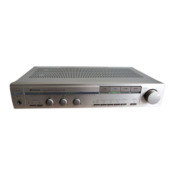
Hitachi HA-4700 Service Manual
Inhaltsverzeichnis
Verfügbare Sprachen
Verfügbare Sprachen
Quicklinks
@HITACHI
SERVICE
SPECIFICATIONS
SO watts • per ChanMl. min.
(Both
RMS. at 8 Ohms
20 kHz. with no
0.02%
total
distortion
50
1 kHz. T.H.D.
SOW/Ch + SOw,'Ch (4 ohms.
1 kHz, T.H.D. 0.02%)
5 HZ—70 kHz '8 ohms. 1/2
Rated T.H.O. 0.05%)
TUNER.
TAPE
10 Hz—70 kHz (+0.5.-3.0 dB)
RIAA
*O.S dB
3
ou.ut)
Less than 0.02%
Less than 0.02%
dWtion
than 0.03%
Irwut
PHONO
MM 2.5 mV (47 k.ohms)
MCO.15
TUNER.
AUX
150 mV/47
TAPE PLAY
150 mV/47
Ou.ut
TAPE REC out
150 mV
220 mV (at 1 kHz. T.H.D.
FEATURES
1. Wide-band, lowdistortion
2. Equalizer circuit with high sensitivity and S/N ratio
3. LED powerindication
4. Power supply section with a powerful punch
MANUAL
(HA4700)
HA4700
HA-3700
3S watts• p« channel. min.
20 HZ to
RMS •t 8 ohms
than
20 kHz. with no more than
harmonic
O.OS% total
horrnmic
distortion.
+ SOw,'Ch (8 ohms.
35 Wich + 35 W/ch (8 ohms,
0.02%)
kHz. T.H.D.
005%)
35 W/ch + 35 Wich (4 Ohms.
1 kHz. T.H.D.O.05%)
S Hz—30kHz (8 ohms.
Rated T.HD. 0.08%)
10 HZ—50 kHz 1+0.5.-3.0 dB)
RIAA
*0.5 dB
Leg
than
Leg than O.OS%
than 0.05%
mV (47 k-ohms)
mv
k-ohms
150 mV/40
k-ohms
150
k-ohms
ISO
mv
180 mV(at 1 kHz. T.H.O.
0.01%)
005%)
• Measured pursuantto the Federal T radeCommission's Trade RegulationRuleon
Claims for Amplifiers.
design for best sound quality
STEREO
July
English
Francais
Specifications and designsmay be changed without noitce for inprovement.
SWul•t0-no"
(IHF A
20 HZ to
PHONO
TUNER. AUX. TAPE
D•mpb"
5. Highly reliable protection circuit
6. Connectionfacilities for two tapedecks(HA470
7. Connection facilities for two pairs of speakers
8. Sleek and chic design
AMPLIFIER
1980
HA-3700
No.
HA4700
dB (MM) 73 dB (MC. input
80 dB
level 0.25 mV)
105 dB
100
dB
40
kHz. 8 ohms)
40 (1 kH2,
dB 1100 HZ)
t8 dB (100
dB (10 kHz)
dB (to
+6 dB 1100 Hz)
+6 dB (100
+4 dB
kHz)
+4 dB (10 kHz)
20 Hz
20
S ICs. 67 transistors
and 71
3
Sl transistm
diodes (24 LED')
diOdes (14 LEOs)
AC 120 V 60 H2. —220 V
AC 120 V60
50/60
HZ. --240 V 50/60
Hz
50/60
Hz. *240
or —120 vn20
vt240
V
or —120 vt220
50/60
50160 HZ
310 VA. -now
1/3 rated
180 W (at
output)
430 W
rated output)
300 W
435 (W) x 83 (H) x 326 (D)
435
x 83 (H) '299
mm (for U.S.A. •nd
mm
435 (W) x 83 (H) x 299 (D)
mm (for Europe and Australia)
435
x 83 (H) x 334 (D)
mm (for Asia arW Latin
American
countries)
6.3 kg
6.4 kg
206
(HA-3700)
HA.3no
ohmi
kHz)
and 46
RZ. •220
V
Hz
V240
V
'3 rate
rated
(D)
Output
Inhaltsverzeichnis

Verwandte Anleitungen für Hitachi HA-4700


Inhaltszusammenfassung für Hitachi HA-4700
- Seite 1 @HITACHI HA-3700 SERVICE MANUAL English Francais (HA4700) (HA-3700) SPECIFICATIONS Specifications and designsmay be changed without noitce for inprovement. HA4700 HA-3700 HA4700 HA.3no SO watts • per ChanMl. min. 3S watts• p« channel. min. SWul•t0-no" (IHF A (Both RMS. at 8 Ohms 20 HZ to RMS •t 8 ohms...
- Seite 2 HITACHI HA-4700/3700 TECHNISCHE DATEN HA4700 HA-3700 HA4700 HA-3700 3S W•tt/KeMl + 35 W•tt/Kaml 50 Watt/K8Ml + SO Kenile (bewe Kaneue •n OHF, A.Z.a) 8 Ohm, 20 Hz—20 kHz, T.H.D. 8 Ohm. 20 HZ—20 kHz. T.H.D. 90 dB (MM) 80 dB OD2%) 0.05%)
-
Seite 3: Zerlegung
HITACHI HA-4700/3700 DISASSEMBLY REPLACEMENT • ZERLEGUNG UND AUSTAUSCH DEMONTAGE ET REMONTAGE • Removing the cover, escutcheon & bottom plate • Ausbma der Abdeckung, der Schildanbringung der Bodenplatte • Déposer le couvercle, Ie cache-entrée et Ia plaque inférieure •Cover Abdeckung 3ø x 10... - Seite 4 (Black) (x4) Fig. 3 3ø X6DT (Silver) Abb. Construction of Power bus Method of exchange the S401 (HA-4700) four pieces Bus line through the insulation OPEN AND RELEASETHE HIRE sheets. öffnen und Draht freigeben Vier durch Isol ierfolfen Ouvrir et relåcher...
-
Seite 5: Adjustment
HITACHI HA-4700/3700 ADJUSTMENT HA-3700 HA-4700 (1) Idle current adjustment (1) Idle current adjustment Set the unit to no signal, speaker select switch OFF, Set the unit to no signal, speaker select switch OFF, Volume control minimum, R750L to the 1 — 2 0'clock... - Seite 6 HITACHI HA-4700/3100 • Caution on assembly before installing the switch PW Board. (I) Be careful in layout during installation of the switch PW (3) Match the marking side (colored side) Of the lead and Board to the sub panelso that the 8core jumper leads mark v stampedon the PW Board when installing the does not touch the input selector switch.
- Seite 7 HITACHI HA-4700/3700 REGLAGE HA4700 qu'il existe une panne dans les transistors du circuit super linéaire (Q705 — 708) et qu'il y a lieu de vérifier (l) Råglagede courantd#attå son état. Régler l'appareil pour ne capter aucun signal,placer le sélecteurde haut-parleursen position "OFF", régler le •...
-
Seite 8: Beschreibung
HITACHI HA-4700/3700 DESCRIPTION CIRCUIT BESCHREIBUNG NEUEN RENSEIGNEMENTS CONCERNANT LE NOUVEAU SCHALTKREISES CIRCUIT HA4700/3700 HA4700/3700 • Super-litwarer Vorspannunß&haltkreis • linear circuit The class B amplifier circuit is constructedas shown in Schaltkreis des Versürkers Fig. 8. A constant idle current flows from the ist in Abb. - Seite 9 Le circuit d'arnplificateur de classe B est construit comme représenté sur la figure 8. Un courant déwatté HA-4700 constant circule du circuit de polarisation fixe et Q3 et Q4 sont altemativement commutés sur marche et arrét •...
- Seite 10 HITACHI HA-4700/3100 0.05 0.01 POWER 0.15 OUTPUT LED O 0.08 0.04 (HA-3700) 0.01 POWER OUTPUT LED a (HA-4700) Fig. 10 Abb. D9S3 0954 0955 0956 0957 0963 0964 INPUT El NGA ENTREE Fig. 11 (HA-4700) Abb. OBOI R405 R406 C416...
- Seite 11 Thecircuit symbol ( ) means a fuw resistor.Whenreplacing (HA-4700) PRINTED WIRING BOARD PRINTPLATTEN PLAN BASE Das%dtsymbol ) steht für Schmelzwiderstand. Beirn Au Other I Le syn%ole de cirwit ) signifie qu'il s•agit d'une résistance 11 pour effectuer son remplacement. Shield...
-
Seite 12: Circuit Diagram
CIRCUIT DIAGRAM • SCHALTPLAN • PLAN DE CIRCUIT (HA-4700) CAUTION: Fuse resistors sure to ug the designated type. PRODI-CT SAFETY NOTE: Components marked with a have to Mfety. SICHERHEITSHINWEIS: Die mit gekennz•ichneter Komp0Mnten haben wichtige SicherheiBaufgaben. Schmelzwiderstan& Sindzur NOTICE DE SECURITE DE FABRICATION;... - Seite 13 The Cirajit Symbol ( ) meansa fue resistor. When replacing it w BASE (HA-3700) PRINTED WRIRING BOARD PRINTPLATTEN PLAN Das Waltsymbol steht für Beim Austa : Other] Le symbolede cirwit ( ) signifiequ'il s'agitd'une page 13 pour effectuer crossis SUB9*1C c:mtrol control Axial leadcylindrical cerarnic capacitor...
- Seite 14 CIRCUIT DIAGRAM • SCHALTPLAN PLAN DE CIRCUIT (HA-3700) CAUTION: are uwd to improve "fety be wre to the desWted type. Always PRODI-ET SAFETY NOTE: Cornponents marked with a A have charæteristks important to Mfety. Die mit #kennzeichneter Konvonenten haben wichtige ZUR BEACHTUNG;...
- Seite 15 HITACHI HA-4700/3700 BLOCK DIAGRAM • BLOCK SCHEMA • SCHEMA (HA-4700) Volume Balance control control Function Tapc Subsonic Relay filter Speaker sw. monitor Equalizer Flat Main PHONO A speaker amp. amp. amp. selector Tone TUNER B speake Loudness Protect 20HZ circuit...
-
Seite 16: Checking The Operation
CHECKING OPERATION PROTECTION CIRCUIT 2. Operation check of the speaker protection circuit Whenthe output circuit is repairedby replacing the power Makesure that.the relay operates(a click sound is heard) transistors,etc., perform an operationcheck on the ASO approx. 6 —10 secondsafter the power switch is turned (Area of SafeOperation)detectioncircuit and the speaker on with the speaker terrninals unloaded (speaker: dis- protection circuit. - Seite 17 HITACHI HA-4700/3700 KONTROLLE FUNKTION SCHUTZSCHALTING Falls die Ausgangsschaltung repariert wurde, indem z.b. die 2. Funktionsprufung der Lautsprecher•SchutzschaItung Leistungstransistorenusw. erneuert wurden, dann muß die Darauf achten,. daß etwa 6 — 10 Sekunden nach dem ASOSchutzschaltung(ASO = Area of SafeOperation) und Einschalten des Neuschalters ein Schaltgeräausch des die Lausprecher-Schutzschaltung k ontroliert werden.
- Seite 18 HITACHI HA-4700/3700 CONTROLE DE FONCTIONNEMENT DU CIRCUIT DE PROTECTION Quand le de sortie est réparé la suite du remplace- 2. Contröle de fonctionnement du circuit de protection ment des transistors de puissance,etc, effectuer une vérifi- de haut•parleur S'assurer q ue le relaisfonctionne(un déclicseproduit) cation de fonctionnement du circuit de détection de type...
-
Seite 19: Subsonic-Filter
FRONT REAR PANEL VORDERE HINTERE BEDIENUNGS TAFEL • PANNEAUX AVANT ARRIERE (HA4700) oooocco 0) POWER switch O) Netzschalter (POWER) (S) Interrupteur d'alimentation (POWER) @PHONES jack @ Prise de casque d'écoute (PHONES) (g) Kopfhörerstecker (PHONES) @SPEAKERS switches @ Commutateurs d'enceintes (SPEAKERS) @Lautsprecherschalter (SPEAKERS) @BASS control... -
Seite 20: Phonesjack
HITACHI HA-4700/3700 (HA-3700) (D POWER switch (j) Netzschalter (POWER) @Interrupteur d'alimentation (POWER) @ PHONESjack @Kopfhörerstecker (PHONES) @ Prise de casque d'écoute (PHONES) @ SPEAKERS switches @Lautsprecherschalter (SPEAKERS) @Commutateurs d'enceintes (SPEAKERS) @ BASS control @Tiefenregler (BASS) @Commande des tonalités graves (BASS) @TREBLE control (DHöhenregler (TREBLE) - Seite 21 HITACHI HA-4700/3700 REPLACEM P RT R AT I TE.TABL PRODUCT SAFETY NOTE: Components wifh a have special charæteristics important to safety. SICHERHEITS{INWEIS: Die mit gekennzeichneten Komponenten haben wichtige Sicherheitsaufgaben. NOTICE DE SECURITE DE FABRICATION: Lescompogno qui sont accompagnés d u symbole caractårisiiquesspWes.
- Seite 22 HITACHI HA-4700/3700 SYMBOL STOCK SYMBOL STOCK DESCRIVTION DESCRIPTION SRD1/8P R606L,R 0129646 Carbon film 43k0 R802 134380 Composition 3.9kQ RChGF SRD1/8P R607L,R HI 29647 Carbon film 47k0 R803 0100661 Carbon film SRD%P loon SRD1/8P Carbon film 1.5k0 R608L,R 1--1129605 SRD1/8P Carbon...
- Seite 23 HITACHI HA-4700/3700 STOCK SYMBOL STOCK SYMBOL DESCRIPTION DESCRIPTION 2SC2546 @ Q402L,R 2329152 2SC2546 @ Q402L,R 2329152 ZD801 2337187 HZ.24-1 2SC2559 0 ZD802 2337187 HZ-24-1 Q701L,R 2367654 ZD803 2337562 HZ-12A-2 2SB648 0 Q702L,R 2328842 ZD804 2337562 HZ-12A-2 2SB6480 Q703L,R 2328742 2SD6680...
- Seite 24 HITACHI HA-4700/3700 STOCK. DESCRIPTION SYMBOL DESCRIITION SYMBOL STOCK 2787231 Connecting band for FINAL ASSEMBLY Escutcheon ass'y 3246492 3• x 10bind doublethreadscrew 4574603 (for escutcheon f ixing) Cover 4411901 Knob ass'y(VOLUME) 3286181 Knob(BASS, TREBLE, B ALANCE) 3286842 4 x 8DTbind screw (for coverfixing)
- Seite 25 HITACHI HA-4700/3700 SYMBOL STOCK SYMBOL STOCK DESCRIPTION DESCRIPTION CAPACITORS C954L,R 0252721 Electrolytic 10gF C955L,R 0252232 Electrolytic 220„F 6.3V C401L,R H240004 Cylindrical ceramic 20pF ± 10% C956L,R 0252725 Electrolytic 47gF C402L,R 0252521 Electrolytic 1 ogF 6.3V C403L,R 0252235 Electrolytic 70gF 6.3V...
- Seite 26 HITACHI HA-4700/3700 SYMBOL STOCK SYMBOL STOCK DESCRIPTION DESCRIPTION SRD1/8P Q703L,R 2328862 5600 29716 R731L,R 129579 Carbon film 39kQ SRD1/8P 2SD7S6 (E) R732L,R Q704L,R 2328872 129645 Carbon film 2SC177S @ SRD1/8P 129583 Carbon film 8200 Q70SL,R 2327913 R733L,R SRD1/8P Carbon film...
- Seite 27 HITACHI HA-4700/3700 SYMÉOL STOCK SYMBOL STOCK DESCRIPTION DESCRIYNON R750L,R 0151339 500Q-(B) (for idle current adj.) 4567432 x 8DT bind screw R751L,R 0151339 SOOO-(B)(for idle current adj.) (for rear plate, other's fixing) R7S2L,R 0151807 4574603 x 10 bind double thread screw...