Dual CD 120 Serviceanleitung
Vorschau ausblenden
Andere Handbücher für CD 120:
- Serviceanleitung (54 Seiten) ,
- Bedienungsanleitung (37 Seiten) ,
- Bedienungsanleitung (12 Seiten)
Inhaltsverzeichnis
Quicklinks
Oual
IRO
Inhalt
Kurzanleitung
Blockschaltbild
Erklärung der Abkürzungen
Verdrahtungsplan
PP Vorverstärkerplatte
PS Servoplatte
PD Digitalplatte
PA Audioplatte
PKI Tastenplatte,
Einstell- und Montagehinweise
Abgleichanleitung
Abgleichlageplan
Meßpunkte
ErsatzteiI-LagepIan
Ersatzteil-Liste
Technische
Daten
Table
des
matiéres
Description
Schema synoptique
Légende
des abréviations
Schema
d'interconnections
PP Platine préamplification
PS Platine
asservissement
PD Platine Traitement Digital
PA Platine
Traitement
PKI Platine touche,
2
PC Platine Control Systéme/Acquisition
Instructions de réglage et de montage
Instruction d'alignement
Plan de position d'alignement
Points
test
Plan de situation des pieces de rechange
Liste de piéces détachées
Characteristiques
Dual GmbH
9208021/483
PC Netzteil
Audio
techniques
Postfach
Service-Anleitung
Service
Instructions
Index
2
Description
4
Block Diagram
8
Explanation
11
Wiring Diagram
13
pp preamplifier
17
PS Servo
21, 25
PD Digital PWB
29, 31
PA Audio
33 37
PKI Key PWB, pc Power PWB
39
Adjusting and Installation Instructions
49
Alignement
52
Positionplan
Testpoints
62
53
Spare Parts position diagram
54
List of spare
56
Technical
3
4
8
11
13
17
21, 25
29, 31
33,37
39
51
52
62
53
54
56
1144 .
7742 St. Georgen/Schwarzwald
AUDIO
CD 120
Manual
de Service
Of abbreviations
PCB
PWB
PWB
Instructions
for alignement
parts
Data
Copyright
3
4
8
11
13
17
21, 25
29, 31
37
39
50
52
62
53
54
56
by Dual
Inhaltsverzeichnis

Verwandte Anleitungen für Dual CD 120


Inhaltszusammenfassung für Dual CD 120
- Seite 1 AUDIO CD 120 Service-Anleitung Service Manual Oual Instructions de Service Inhalt Index Kurzanleitung Description Blockschaltbild Block Diagram Erklärung der Abkürzungen Explanation Of abbreviations Verdrahtungsplan Wiring Diagram PP Vorverstärkerplatte pp preamplifier PS Servoplatte PS Servo PD Digitalplatte 21, 25 PD Digital PWB...
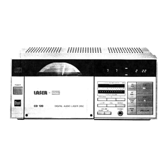
- Seite 2 18 —Headphones Jack. DESCRIPTION 8 —programming Indicator Lamp. 9 —Digital Counter. 19 —Set of button for selecting disc 1 — Power Switch. tracks. Indicates, in minutes and seconds: 2 — Disc Door. • The total playing time of the track selec- 20 —Repeat Button.
-
Seite 3: Block Diagram
Blockschaltbild • Block Diagram Schema Synoptique — Version 2 — M'RROR ENVELOPE DETECTION ICa05 003104/05 2Kx8bits 'COJ TRANS VERSAL 01-41T FILTER MIRROR C aot DETECTION NRZi 34.5744 AMBLE 0306 OE MODULATION MAIN ERROB 0302 SIGNAL OUTPUT DETECTION ADORES FOCUS 0402 SYNCHRO pHOTO- CATA... - Seite 4 003104k)S TRANS 2K.8bits IC406 VERSAL R408 ca18L FILTER IC409L 'C408L IC407L IC401 UNSCR • NRZi AMBLE MODULATION OEMOOUL. ERROR DETECTION OUTPUT 0402 ADORESS SYNCHRO CC*4TROL REVISION SYMB IC403 EDGE 4,321B 'Ca02 LASER DIGITAL DRIVER IC 407R 'C 409B CLOCK MUTE CONTROL IC404 GENERATON...
- Seite 5 Blockschaltbild • Block Diagram Schema Synoptique — Version 1 — vect '2 v • IC 501 L OUTPUT NTROL MPXL SHL • IC 404 'C 407 MPXR MPXL MPXR TAIL CPSOtL RCH) TA2L E MPHASIS RY 552 IC504L TA4 L MUTING RY 551 ADJ.
- Seite 6 Bedeutung Bedeutung Symbole Explanation Symbole Explanation Désignation Désignation Zugang Disc-Motor-SpuIe ACCESS Access DMCB Disc motor coil B Acces Bobine B du moteur disque RAM Adressen Disc-Motor-SchaIter RAM addressing DMSW Disc motor switch AD 10 Bus d'adresse Interrupteur moteur disque A-Takt Leiser A synchro A SYN...
- Seite 7 Bedeutung Bedeutung Symbole Explanation Symbole Explanation Désignation Désignation Linker Kanal, variabler Ausgangspegel GRII Anzeigegitter LVAL Left channel variable output Display grid Commande afficheurs Sortie variable BF voie gauche GR18 Discmotor-HaIIsteuerung Haupt-Takt 4,321 MHz Master clock Hall intensity Régulation en vitesse du moteur disque Horloge de référence Discmotor-SpuIensteuerung Haupt-Takt...
- Seite 8 Bedeutung Bedeutung Symbole Explanation Explanation Symbole Désignation Désignation Stop Rechter Kanal, Analogsignal STOP Stop Right channel analog signal Arrét Signal analogique voie droite Spurführungs-Spule Datenbus RD O Tracking Actuator Data Transducteur de suivi de piste Bus de données Übergangsdetektor Wiederholung TDET Transition detector...
-
Seite 9: Wiring Diagram
Schema d'lnterconnexions Verdrahtungsplan Wiring Diagram PP = Vorverstärker Preamp R w. B. brown red Platine Commande —LEOI Laser/Preamplifi- GRIO cation LEO K PKI = Tastenplatte GRIO Laser Localisator Key Circuit FF-Connector Platine Commande : KEY LEDK Output Volume PS = Servo-Platte Servo P.W.B. -
Seite 10: Pp Vorverstärker-Platte
PP Vorverstärker-Platte • Preamp P.W.B. Circuits Imprimés Platine Commande Laser/ Préamplification LB1275 2SC4580 LM318P 2SB562@ RD6.2EN1 HD74159P HD44820A75 2SA1015 TC5066BP HA-12049 TC4001BP TL4558P-C TC4528BP LASER DIODES ICOI (HAI 2049) Optischer Abtaster P.U. SLIDE Pick Up MOTOR Commande Laser Lens }LBG LENS ACTUATOR AMP. - Seite 11 Schema Platine Commande Laser/ Préamplification Pre Amp Circuit • PP Vorverstärker 7VST CP02 CPOI cp601 (100K -Vcc -vcc ROG2 R621410K •vcc 2St458 t Icos IY318P- IC03 l"318P coz»3 0.7 0.022 .022 ROS8 10 R630 DCND -29V ROS9 R057 0604 couo R061 120k u,7K...
- Seite 12 Servo-Platte Servo P. W B. Circuit Imprimé Platine Asservissement TC4013BP 2SC4580 HD44700A17 M54560P TC4066BP LA6393D 2SD468 0 1S2076 2sc1015 TC4528BP TL4558P-C 2SB562(D IR3702 2SK246BL HA17901P TP.2 TP.8 TP.IO TP.9 TP.12 TP.6 TP.7 TP,5 R114 a 302 *289 C300Q30TT 04 Ä306 R309 MOTOR 0 200...
-
Seite 13: Servo-Schaltung
Servo-Schaltung Servo Circuit •Schema PlatineAsservissement 1183 R267 gsq 47/6.3 NOTER3 5.9K 07/6.3 R2€9 39K "00kHZ R268 39K C2S5 1.7'6.3 9275 Focus mTER7 3.9K C257 47/6.3 SERVO yucsnc R2 7 39K GAIN ADJ R276 39K R278 MOTER5 3.9K 07/6.3 0167 0750 O.SC MOTOR R2fß... - Seite 14 Digital-Platte IC402(MB15529) IC403(HD61901 ) IC404(HD61902 RAO. Digital P.WB. OEuoouLAtON soar A MEMORY ccsl LOGL Circuit Imprimé ADORE SS •cur r CON'AOC SSYNC Platine Traitement Digital CARAM LOGE SYNCHRONIZING CARAY oec00EA DS'R DstF TEST F TEST C — Version 1 — SYNCHAON'ENG SIGNAL POISE...
- Seite 15 Digitale Datenverarbeitung• Digibl Circuit Schema Platine Traitement Digital — Version 1 — 0.01 ,'25 Vor: 1 RD6 RD5 80 1 TCI 20vcc TP.8 00/6. E T(AI Edqe)25 I,'DSTR RD17 TEST( reset 124 56 p ROD7 Edge)25 SSDATA 0.01 N)27 9 1/01 asys 1/03 IISSYNC...
- Seite 16 2SC535@ 2sc1213(t) 1S2076 HD14053BP PCM53JG.v uPC4081C HD61902 HM6116P-4 HD61901 MB15529 cxo-041 Digital PW B. Circuit Imprimé Platine Traitement Digital — Version 2 — IC405(HM61 16P—4 ) IC404(HD61902) IC403(HD61901 IC402(MB1 5529) RDO--S RD?RD6 TCIFSTP rusrp MEMORY OEMOOULAT'ON LOW. COSI ASYNC tr_2SIF' , RDO-2 CIRC,uit ECODER...
-
Seite 17: Digitale Datenverarbeitung
Digitale Datenverarbeitung • Digital Circuit Schema Platine Traitement — Version 2 — 0.01 Xtol IC401 no-041 1RD6 0402 sc535 TEST(AII dge)2 1 TCI TEST(P e set 6 SHR TEST (1st age) 2 TP8 Z 2 DATA $ Epq IN) 27 TACK X K29 9 DAI... - Seite 18 Audio-Schaltung • Audio Circuit PA Audio-matte Audio RWB. Schema Platine Traitement Audio Circuit Imprimé Platine Traitement Audio — Version 1 — — Version 1 — R507L 5, 6K C509L C509R R509R RS09L 100/16 100/16 C508L C508R R510L R510R 100/16 R515L (Fuse resisto ( Fuse...
-
Seite 19: Pa Audio-Schaltung
Audio-Platte • Audio P.W.B. PA Audio-Schaltung • Audio Circuit Circuit Imprimé Platine Traitement Audio Schema Platine Traitement Audio — Version 2 — — Version 2 — C509L D901 , 27K, -I All RS12L C513L 0.01 180<NFR' RS2Lt 1.5K RS>3R R525L C517R- .C5 k R554 2.7K... - Seite 20 MTL 1 PKI Tastenplatte Key RW.B. Platine touche — Version 1 +2 — FLUORESCENTDISPLAYTUBE NetteiI-Platte SCENT D Power P.W B. Platine Control Systeme/ Acquisition — Version 1 +2 — PAUST PLAY VOLUME CONB CONB INSERT a is 7ßiftm PA p.l,'VB VAR.
-
Seite 21: Power Circuit
Netzteil Power Circuit • Schema d'Alimentation — Version 1 — 000n MOTOR LIMIT TURN MOTOR PICK LT-3322 (VOL IND) PHOTO LASER 0100ES DIODES CO.'S nn n 1 P.W.B. PR F Mi—iiii L FIX OUT TACG L VAR our CKEXT tvcc DATA} FPRE DATA2... - Seite 22 1. Die m — Version 2 — N&teil • Power Circuit • Schema hande werdf OOOR MOTOR 2. DerA SWITCH cnsC einhe schie,' LT-3322 nieme IND) PHOTO LASER 3. Direkl Oi00ES otooes 6800P Strahl Eins Sollen werden, Zustand Mit der setzen.
- Seite 23 Remarques importantes: Important Notes: Wichtige Hinweise: I. TraitezIa piste flexible avec précaution, 1. As a replacementof the flexible board l. Die flexible Leiterbahn sorgfältig be- ellene peut pas étre échangée! is not possible,handle it with care. handeln,sie kann nicht ausgetauscht 2 Le chariot de lecture avec optic et unité...
-
Seite 24: Designationof Printedcircuits Andtheir Location In The Player (Fig. 4)
Fig. 4 Fig. 3 Désignation des circuit imprimés Designationof printedcircuits andtheir LeiterpIatten-Bezeichnung undihre Lage et leur positiondans I'appareil(Fig.4) location in the player (Fig. 4) im Gerät (Fig. 4). PA: Platine traitement AUDIO PA: Audio circuit PA: Audio-Platte PP: Platine commande laser/ PP: Pre-amp circuit PP: Vorverstärker-Platte préamplificateur... - Seite 25 Laser beam Le faisceau laser Laserlicht La lecture du compact disc se fait å l'aide Das Gerät arbeitet mit einem Halbleiter- A compact disc is played by being scan- Laser, dieses Licht ist unsichtbar aber ned by a laser beam. The (light) beam d'une diode laser.
- Seite 26 2. Sur l'ensemble de lecture optique 2. On the optic scanner assembly, do not 2. Am Pick-up-Schlitten dürfen die pas desserrer ou déréglerles vis 9B loosen or readjust screws 9B on the Schrauben 9B für die Laser-Diode, de la diode laser, 9 C photo-diode laser diode, 90 on the photo-diode den Opto-Sensor 9C (Fotodiode)und 9A lecteur optique.
- Seite 27 Damit Wird der Verriegelungshebel IOH player IOD cause pressure to trigger the deux goupilles 101du socle de I'appareil IOD exercent une poussée pour déclen- ausgelöst und die CD-Platte IOE an den holding lever IOH; the disc is held bet- Antrieb IOC des Disc-Motors mit dem ween the clamp IOG and the turntable...
- Seite 28 13 c Enlargeddiagram 13 E 13 D 13 A fig. 13 Laufwerk Mechanical assy Flexible L'ensemblemécanique Leiterfolie Mikroschalter Plattenschacht Flexible P.W.B. (Schacht geschlossen) Door (Loading mech.) ass'y Schlittenmotor Micro switch Motor Obere (forPickup d rive)Führungsschiene (for D oor c losed l imit) Guide rail Laser diode (Upper)
- Seite 29 Removing the mechanical assembly Dépose de I'ensemble mécanique Ausbau des kompletten Laufwerkes The assembly can only be removed when L'ensemble ne peut étre déposé que Ie Das Laufwerk kann nur mit geöffnetem volet ouvert Séparer Ia partie avant du Plattenschacht ausgebaut werden.
- Seite 30 Remontage du volet porte-disque Reassembling the disc holder flap Einbau des Plattenschachtes (Fig. 15et Fig. 16) (Figs. 15and 16) Kurbelarm 15C auf die Achse des Gear- Placer Ia manivelle 150 sur I'axe du mo- Set the crank 15Con the motor arm 15D. Motors 15D setzen.
-
Seite 31: Einbau Des Disc-Motors (Fig. 25)
Einbau des Disc-Motors (Fig. 25) Reassembling the turntable motor Remontage du moteur T.D.(Fig.25) Lagerblock durch den Schlitten führen, (Fig. 25) Poser Ie moteur dans son logement, le um 900 drehen und in der Aufnahmeboh- Set the motor in its housing, turn it 900, tourner de 900, placer Ies quatre vis de rung der Grundeinheit fixieren. - Seite 32 @ CHECK DISC @ DOOR ASSYALIGNING @DOOR ASSYALIGNING O) MECH. STAND SPACER @TURNTABLE @ SPACER f or ADJUSTMENT INSTALLATION of P.U. INNER LIMIT Fig. 20 Adjusting the laser switches Réglage des interrupteurs å lames Einstellung der Mikroschalter Schalter Pick-up-Endanschlag 20 B Switch for detecting end of disc 20B Interrupteur de détection fin de disque...
-
Seite 33: Abgleichanleitung
Abgleichanleitung Klappen Sie bitte Seite 52 auf. Abgleich- Abgleich- MeBgeråt Einstellung Einstellung Signalquelle bemerkung Anschluß position Signalquelle Gerät LASER OUTPUT EFM-Sig. auf 600 mV einstellen osz. an TP 11, bezogen auf GND (Fig. I) TPG (GND) R 021 PLAY: CD-Platte Kontrolle: Digit-Voltmeter 1,32 V -... -
Seite 34: Alignment Instructions
Alignment Instructions Please fold open page 52. Adjustment Observations Signal Source Adjustment of Function Measurement signal source points points LASER OUTPUT osc to TP 11, Adjust EFM signal 600 mV TPG (1) relative to ground (GND) Fig. I Compact disc PLAY R 021 1.32 V - 2.2 V = 60 -100... - Seite 35 Instructions d'alignement Abgleichlageplan • Positionplan for alignment • Plan de position d'alignement Source du signal Réglage de ta Fonction Points de Mesure Points Observations Back Front Side Side source du signal de réglage Output TTL level LASER OUTPUT osc. surTP 11, Régl.
- Seite 36 Ersatzteile • Replacement parts • Piéces détachée • CD 120 Ersatzteillageplan • Spare parts position diagram Art-Nr. Stck Bezeichnung Bezeichnung Pos. Art. -Nr. Stck Pian de situation des piéces de rechange 273804 Blechank kpl. D 201 273871 Diode 1 S 2076...
- Seite 37 Stck Bezeichnung Art.-Nr. POS. Pos. Art.-Nr. Stck Bezeichnung Transistor 2 SC 458 C 273341 Q 551 IC 704 275188 IC UPC 7915 H Transistor 2 SC 458 C 273841 Q 552 IC 705 273971 IC UPC 7908 H Transistor 2 SC 1213 C Q 901 273870 IC 800...
-
Seite 38: Technical Data
Technische Daten Frequenzgang • • • • • • 5-20.000 0.5 dB. Dynamikumfang > 93 dB. Signal-Fremdspannungsabstand > 94 dB. Klirrgrad . < 0,003 % Übersprechdämpfung . > 92 dB (bei 1 kHz). Gleichlaufschwankungen < 0,001 %. Ausgangsspannung Abtastfrequenz 44,1 kHz. Quantisierung 16 Bit linear/KanaI.