Stahl 261403 Betriebsanleitung
ENGLISH
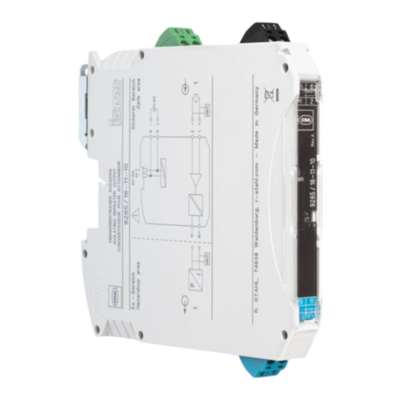
Isolating repeater output
4. Installation
1. Safety regulations
1.1 Installation notes
•
The device is an item of associated equipment with an EPL [Ga], [Da] (ATEX
EN / UL 61010-1:
category 1) with "intrinsic safety" type of protection and can be installed in zone
2 potentially explosive areas as an EPL Gc (ATEX category 3) device.
Intrinsically safe circuits can be led up to zone 0/zone 20. It satisfies the
requirements of the following standards. Comprehensive details are to be
found in the EU Declaration of Conformity which is enclosed and also available
on our website in the latest version:
IEC/EN 60079-0, IEC/EN 60079-7, IEC/EN 60079-11
•
Installation, operation, and maintenance may only be carried out by qualified
electricians. Follow the installation instructions as described. When installing
and operating the device, the applicable regulations and safety directives
(including national safety directives), as well as general technical regulations,
must be observed. For the safety data, refer to this document and the
certificates (EU type examination certificate and other approvals if
appropriate).
•
The device must not be opened or modified. Do not repair the device yourself,
replace it with an equivalent device. Repairs may only be carried out by the
manufacturer. The manufacturer is not liable for damage resulting from
violation.
•
The IP20 degree of protection (IEC/EN 60529) specifies that the device is
intended for use in a clean and dry environment. Do not subject the device to
mechanical and/or thermal stress that exceeds the specified limits.
•
The device complies with the EMC regulations for industrial areas (EMC
class A). When using the device in residential areas, it may cause radio
interference.
•
The switches of the device that can be accessed may only be actuated when
the power supply to the device is disconnected or when it has been ensured
that there is no potentially explosive atmosphere present.
•
Only use copper connecting cables.
1.2 Intrinsic safety
•
The device is approved for intrinsically safe (Ex i) circuits up to zone 0 (gas)
and zone 20 (dust) in the Ex area. The safety technology values for intrinsically
The assignment of the connection terminal blocks is shown in the block diagram.
safe equipment and the connecting lines must be observed for the hook-up
(2)
process (IEC/EN 60079-14) and the values specified in this installation note
The device can be snapped onto all 35 mm DIN rails according to IEC/EN 60715.
and/or the EU type examination certificate must be observed.
When using the 9294/31-12, first insert it to bridge the power supply. (3)
•
The specified ambient temperature range of -40°C ≤ T
≤ +70°C refers
amb
to the temperature inside the housing.
•
When carrying out measurements on the intrinsically safe side, observe the
relevant regulations regarding the connection of intrinsically safe equipment.
Use only these approved measuring devices in intrinsically safe circuits.
4.1 Power supply
•
If the device was used in circuits which are not intrinsically safe, it is forbidden
The supply voltage can be supplied via terminal points 5 and 6 or via the pac-Bus
to use it again in intrinsically safe circuits. Label the device clearly as being not
9294.
intrinsically safe.
1.3 Installation in the Ex area (zone 2)
Supply via terminal set 9194/50-01
You can connect the supply voltage directly with the bus connector by way of the
•
Observe the specified conditions for use in potentially explosive areas! Install
terminal set.
the device in a suitable, approved housing that meets the requirements of IEC/
Adhere to the maximum feed-in of 4 A.
EN 60079-0 and has at least IP54 protection. Also observe the requirements
of IEC/EN 60079-14.
Feed-in via supply module type 9193
Supply module type 9193 is used to feed in the supply voltage to the DIN rail bus
•
In potentially explosive areas, only snap the device onto or off the pac-Bus
9294 or connect and disconnect the cables when the power is disconnected.
connector.
•
The device must be stopped and immediately removed from the Ex area if it is
damaged, was subject to an impermissible load, stored incorrectly or if it
malfunctions.
1.4 Potentially dust-explosive areas
•
The device is not suitable for installation in zone 22.
•
If you nevertheless intend to use the device in zone 22, you must install it in a
housing according to IEC/EN 60079-31. Observe the maximum surface
temperatures in this case. Adhere to the requirements of IEC/EN 60079-14.
•
Connection to the intrinsically safe circuit in areas with a danger of dust
explosions (zone 20, 21 or 22) is only permitted if the equipment connected to
this circuit is approved for this zone (e.g., category 1D, 2D or 3D).
•
The group IIB values can be used for areas with combustible dust and in
mining applications.
1.5 Safety-related applications (SIL)
NOTE: Risk of damage to equipment
When using the device in safety-relevant applications, follow the
instructions in the safety user manual at r.stahl.com, web code "9265A".
2. Short description
The isolating repeater output helps in controlling the intrinsically safe (Ex-i) I/P
converters, control valves and indicators installed in the Ex area.
The device isolates and transmits 0/4 mA ... 20 mA signals to the Ex area with
intrinsic safety.
For operating the intrinsically safe SMART actuators, the analog measuring value
can be overlayed with digital communication signals (HART) on the Ex or non-Ex
side and transmitted bidirectionally in an electrically isolated manner.
The device enables open-circuit and short-circuit monitoring.
You can switch the short-circuit detection on or off using the DIP switch.
An open or short-circuited field circuit causes a high input impedance on the
controller side, thus enabling open-circuit and short-circuit monitoring via the
control system.
Readiness for operation is indicated via a green LED.
The device is approved for safety-related applications up to SIL 2 (1oo1) / SIL 3
(1oo2).
3. Operating and indicating elements (1)
1 Green "PWR" LED, power supply
2 Connection terminal blocks for the safe area (black/green)
3 DIP switch
4 Connection terminal blocks for the Ex area (intrinsically safe Ex i, blue)
ENGLISH
Trennübertrager Ausgang
NOTE: Electrostatic discharge
1. Sicherheitsbestimmungen
Take protective measures against electrostatic discharge before opening
1.1 Errichtungshinweise
the front cover!
•
Das Gerät ist ein zugehöriges Betriebsmittel mit einem EPL [Ga], [Da] (ATEX
Kategorie 1) der Zündschutzart "Eigensicherheit" und kann als Gerät mit dem
•
Disconnecting devices and branch circuit protection with suitable AC or
EPL Gc (ATEX Kategorie 3) im explosionsgefährdeten Bereich der Zone 2
DC rating shall be provided in the building installation.
installiert werden. Die eigensicheren Stromkreise können bis in die Zone 0 /
•
The device is intended for installation in a control cabinet or in a
Zone 20 geführt werden. Es erfüllt die Anforderungen der folgenden Normen.
comparable enclosure. The device may only be operated when it has
Genaue Angaben sind der EU-Konformitätserklärung zu entnehmen, die
been installed. The control cabinet must meet the requirements of UL/
beiliegt und auf unserer Webseite in der aktuellsten Version zu finden ist:
IEC 61010-1 in terms of protection against spread of fire and protection
IEC/EN 60079-0, IEC/EN 60079-7, IEC/EN 60079-11
against electric shock or burn.
•
Die Installation, Bedienung und Wartung ist von elektrotechnisch
•
Provide for a switch/circuit-breaker in the vicinity of a device that is
qualifiziertem Fachpersonal durchzuführen. Befolgen Sie die beschriebenen
marked as disconnect device for this device.
Installationsanweisungen. Halten Sie die für das Errichten und Betreiben
•
Provide overcurrent protection (I ≤ 6 A) within the installation.
geltenden Bestimmungen und Sicherheitsvorschriften (auch nationale
•
For UL applications, install a UL-approved (JDYX2) overcurrent
Sicherheitsvorschriften) sowie die allgemeinen Regeln der Technik ein. Die
protection unit (I ≤ 6 A, U > 30 V DC, usable in DC circuits, slow-
sicherheitstechnischen Daten sind diesem Dokument und den Zertifikaten
blow) in the installation.
(EU-Baumusterprüfbescheinigung, ggf. weitere Approbationen) zu
•
To protect the device against mechanical or electrical damage, install it
entnehmen.
in suitable housing with an appropriate degree of protection according
•
Öffnen oder Verändern des Geräts ist nicht zulässig. Reparieren Sie das Gerät
to IEC/EN 60529.
nicht selbst, sondern ersetzen Sie es durch ein gleichwertiges Gerät.
•
During maintenance work, disconnect the device from all effective
Reparaturen dürfen nur vom Hersteller vorgenommen werden. Der Hersteller
power sources.
haftet nicht für Schäden aus Zuwiderhandlung.
•
If the device is not used as described in the documentation, the intended
•
Die Schutzart IP20 (IEC/EN 60529) des Geräts ist für eine saubere und
protection can be negatively affected.
trockene Umgebung vorgesehen. Setzen Sie das Gerät keiner mechanischen
und/oder thermischen Beanspruchung aus, die die beschriebenen Grenzen
•
Thanks to its housing, the device has basic insulation to the neighboring
überschreitet.
devices, for 300 Veff. If several devices are installed next to each other,
this has to be taken into account, and additional insulation has to be
•
Das Gerät erfüllt die Funkschutzbestimmungen (EMV) für den industriellen
installed if necessary! If the neighboring device is equipped with basic
Bereich (Funkschutzklasse A). Beim Einsatz im Wohnbereich kann es
insulation, no additional insulation is necessary.
Funkstörungen verursachen.
•
The voltages applied at the input, output, and power supply are extra-
•
Die zugänglichen Schalter des Geräts dürfen nur betätigt werden, wenn das
low voltages (ELV). Depending on the application, it can be the case
Gerät stromlos ist oder wenn sichergestellt ist, dass keine explosionsfähige
that a voltage that is dangerous to the touch (>30 V AC / >60 V DC)
Atmosphäre vorhanden ist.
against the ground could be present on the device. In this case, a safe
•
Verwenden Sie als Anschlusskabel nur Kupferleitungen.
galvanic isolation exists between the input side and the output side.
1.2 Eigensicherheit
•
Das Gerät ist für eigensichere (Ex i) Stromkreise bis in Zone 0 (Gas) und Zone
20 (Staub) des Ex-Bereichs zugelassen. Die sicherheitstechnischen Werte
der eigensicheren Betriebsmittel sowie der verbindenden Leitungen sind bei
der Zusammenschaltung (IEC/EN 60079-14) zu beachten und müssen die
NOTE
angegebenen Werte dieser Einbauanweisung bzw. der EU-
Please also observe the direction of the module and pac-Bus 9294 when
Baumusterprüfbescheinigung einhalten.
snapping into position:
•
Der angegebene Umgebungstemperaturbereich von -40 °C ≤ T
snap-on foot at the top and connector on the left.
bezieht sich auf die Temperatur in dem Gehäuse.
•
Beachten Sie bei Messungen auf der eigensicheren Seite unbedingt die für
das Zusammenschalten von eigensicheren Betriebsmitteln geltenden
einschlägigen Bestimmungen. Verwenden Sie in eigensicheren Stromkreisen
nur für diese zugelassene Messgeräte.
•
Wurde das Gerät in nicht eigensicheren Stromkreisen eingesetzt, ist die
erneute Verwendung in eigensicheren Stromkreisen verboten! Kennzeichnen
Sie das Gerät eindeutig als nicht eigensicher.
1.3 Installation im Ex-Bereich (Zone 2)
•
Halten Sie die festgelegten Bedingungen für den Einsatz in
explosionsgefährdeten Bereichen ein! Setzen Sie bei der Installation ein
geeignetes, zugelassenes Gehäuse der Mindestschutzart IP54 ein, das die
Anforderungen der IEC/EN 60079-0 erfüllt. Beachten Sie auch die
Anforderungen der IEC/EN 60079-14.
•
Das Auf- und Abrasten auf den pac-Bus 9294 bzw. das Anschließen und das
Trennen von Leitungen im explosionsgefährdeten Bereich ist nur im
spannungslosen Zustand zulässig.
•
Das Gerät ist außer Betrieb zu nehmen und unverzüglich aus dem Ex-Bereich
zu entfernen, wenn es beschädigt ist, unsachgemäß belastet oder gelagert
wurde bzw. Fehlfunktionen aufweist.
1.4 Staubexplosionsgefährdete Bereiche
•
Das Gerät ist nicht für die Installation in der Zone 22 ausgelegt.
•
Wollen Sie das Gerät dennoch in der Zone 22 einsetzen, dann müssen Sie es
in ein Gehäuse gemäß IEC/EN 60079-31 einbauen. Beachten Sie dabei die
maximalen Oberflächentemperaturen. Halten Sie die Anforderungen der IEC/
EN 60079-14 ein.
•
Nehmen Sie die Zusammenschaltung mit dem eigensicheren Stromkreis in
staubexplosionsgefährdeten Bereichen der Zonen 20, 21 bzw. 22 nur vor,
wenn die an diesen Stromkreis angeschlossenen Betriebsmittel für diese
Zone zugelassen sind (z. B. Kategorie 1D, 2D bzw. 3D).
•
Die Werte der Gruppe IIB können für Bereiche mit brennbaren Staub und in
Bergbaubereichen genutzt werden.
1.5 Sicherheitsgerichtete Anwendungen (SIL)
ACHTUNG: Sachschaden möglich
Beachten Sie bei Einsatz des Geräts in sicherheitsgerichteten
Anwendungen die Anweisungen im Sicherheitshandbuch unter r-
stahl.com, Webcode "9265A".
2. Kurzbeschreibung
Der Trennübertrager Ausgang dient zum Ansteuern von im Ex-Bereich
installierten eigensicheren (Ex-i) I/P-Umformern, Regelventilen und Anzeigen.
Das Gerät trennt und überträgt 0/4 mA ... 20 mA-Signale eigensicher in den Ex-
Bereich.
Für den Betrieb von eigensicheren SMART-Aktoren können dem analogen
Messwert digitale Kommunikationssignale (HART) auf der Ex- oder Nicht-Ex-
Seite überlagert und bidirektional galvanisch getrennt übertragen werden.
Das Gerät ermöglicht die Überwachung auf Leitungsbruch und Kurzschluss.
Sie können die Kurzschlussüberwachung mithilfe der DIP-Schalter aus- oder
einschalten.
Ein offener oder kurzgeschlossener Feldstromkreis verursacht auf der
Steuerungsseite eine hohe Eingangsimpedanz und ermöglicht so eine
Leitungsbruch- und Kurzschlussüberwachung durch das Steuerungssystem.
Die Betriebsbereitschaft wird durch eine grüne LED angezeigt.
Das Gerät ist für sicherheitsgerichtete Anwendungen bis SIL 2 (1oo1) / SIL 3
(1oo2) zugelassen.
3. Bedien- und Anzeigeelemente (1)
1 LED grün "PWR" Spannungsversorgung
2 Anschlussklemmen für den sicheren Bereich (schwarz / grün)
3 DIP-Schalter
4 Anschlussklemmen für den Ex-Bereich (eigensicher Ex i, blau)
DEUTSCH
DEUTSCH
4. Installation
ACHTUNG: Elektrostatische Entladung
Treffen Sie Schutzmaßnahmen gegen elektrostatische Entladung, bevor
Sie den Frontdeckel öffnen!
EN / UL 61010-1:
•
In der Gebäudeinstallation müssen Trennvorrichtungen und
Nebenstromkreisschutzeinrichtungen mit geeigneten AC- oder DC-
Werten vorgesehen werden.
•
Das Gerät ist für den Einbau in einen Schaltschrank oder in ein
vergleichbares Gehäuse vorgesehen. Das Gerät darf nur eingebaut
betrieben werden. Der Schaltschrank muss den Anforderungen eines
Brandschutzgehäuses der Sicherheitsnorm UL/IEC 61010-1
entsprechen und einen adäquaten Schutz vor elektrischem Schlag oder
Verbrennungen bieten.
•
Sehen Sie in der Nähe eines Geräts einen Schalter/Leistungsschalter
vor, der als Trennvorrichtung für dieses Gerät gekennzeichnet ist.
•
Sehen Sie eine Überstromschutzeinrichtung (I ≤ 6 A) in der Installation
vor.
•
Für UL-Anwendungen sehen Sie eine UL-zugelassene (JDYX2)
Überstromschutzeinrichtung (I ≤ 6 A, U > 30 V DC, verwendbar in DC-
Stromkreisen, träge) in der Installation vor.
•
Bauen Sie das Gerät zum Schutz gegen mechanische oder elektrische
Beschädigungen in ein entsprechendes Gehäuse mit einer geeigneten
Schutzart nach IEC/EN 60529 ein.
•
Trennen Sie das Gerät bei Instandhaltungsarbeiten von allen
wirksamen Energiequellen.
•
Wenn das Gerät nicht entsprechend der Dokumentation benutzt wird,
kann der vorgesehene Schutz beeinträchtigt sein.
•
Das Gerät besitzt durch sein Gehäuse eine Basisisolierung zu
benachbarten Geräten für 300 V
Installation mehrerer Geräte nebeneinander und installieren Sie ggf.
eine zusätzliche Isolation. Wenn das benachbarte Gerät eine
Basisisolierung besitzt, ist keine zusätzliche Isolierung notwendig.
•
Die an Eingang, Ausgang und Versorgung anliegenden Spannungen
sind Extra-Low-Voltage (ELV)-Spannungen. Es kann je nach
Anwendung vorkommen, dass eine berührgefährliche Spannung
(>30 V AC / >60 V DC) gegen Erde am Gerät anliegt. Für diesen Fall ist
eine sichere galvanische Trennung zwischen Eingangs- und
Ausgangsseite vorhanden.
Die Belegung der Anschlussklemmen zeigt das Blockschaltbild. (2)
Das Gerät ist auf alle 35-mm-Hutschienen nach IEC/EN 60715 aufrastbar. Bei
Einsatz des 9294/31-12 legen Sie diesen zur Brückung der
≤ +70 °C
amb
Spannungsversorgung zuerst ein. (3)
ACHTUNG
Beachten Sie in diesem Fall unbedingt die Aufrastrichtung von Modul und
pac-Bus 9294:
Rastfuß oben und Steckerteil links!
4.1 Spannungsversorgung
Sie können die Versorgungsspannung über die Klemmstellen 5 und 6 oder den
pac-Bus 9294 einspeisen.
Einspeisung über Klemmenset 9194/50-01
Über das Klemmenset können Sie die Versorgungsspannung direkt mit dem
Busverbinder verbinden.
Halten Sie die maximale Einspeisung von 4 A ein.
Einspeisung mittels Einspeisemodul Typ 9193
Das Einspeisemodul Typ 9193 wird zur Einspeisung der Versorgungspannung
auf den Hutschienen-Busverbinder eingesetzt.
R. STAHL Schaltgeräte GmbH
Am Bahnhof 30, 74638 Waldenburg, Germany
Tel: +49 7942 943-0 Fax: +49 7942 943-4333
Internet: r-stahl.com E-Mail: info@r-stahl.com
r-stahl.com
DE
Betriebsanleitung
EN
Operating instructions
9265/16-11-10
1
. Beachten Sie dieses bei der
eff
2
Hazardous area
P
1
I
HHT
3
A
D
4
AWG 24-14
92../..s
0,2-2,5 mm
A
7 mm
B
0,5-0,6 Nm
5-7 lb In
MNR 1029336
261407 / 926560310010 / V03
2024-02-20
261403
2
1
|
2
5
6
1
2
1
PWR
1
3
2
I
II
10
11
4
10
|
11
Safe area
pac-Bus
24 V
− +
6
− −
24 V DC
5
+
11−
2
− −
1
+
10+
1
HHT
B
C
E
5
2
92../..k
DNR 83194015 - 03
Inhaltsverzeichnis

Verwandte Anleitungen für Stahl 261403


Inhaltszusammenfassung für Stahl 261403
- Seite 1 When using the device in safety-relevant applications, follow the staubexplosionsgefährdeten Bereichen der Zonen 20, 21 bzw. 22 nur vor, instructions in the safety user manual at r.stahl.com, web code "9265A". wenn die an diesen Stromkreis angeschlossenen Betriebsmittel für diese Zone zugelassen sind (z. B. Kategorie 1D, 2D bzw. 3D).
-
Seite 2: Technical Data
Kurzschlusserkennung von >0,2 mA nutzbar. Technical data Technische Daten Connection method Anschlussart Screw connection Schraubanschluss 9265/16-11-10 261403 Hardware version Hardwareversion Input data ! CAT II (250 V against ¿) Eingangsdaten ! CAT II (250 V gegen ¿) Input signal Function (short-circuit detection off) Eingangssignal Funktion (Kurzschlusserkennung aus) 0 mA ... - Seite 3 In caso di impiego del dispositivo in applicazioni di sicurezza, attenersi alle • Les valeurs du groupe IIB peuvent être utilisées dans des zones contenant istruzioni del manuale di sicurezza sul sito web r-stahl.com, codice web des poussières inflammables et dans les zones d'exploitation minière. "9265A".
-
Seite 4: Dati Tecnici
Caractéristiques techniques Collegamento Type de raccordement Connessione a vite Raccordement vissé 9265/16-11-10 261403 Versione hardware Version matériel Dati d'ingresso ! CAT II (250 V verso ¿) Données d'entrée ! CAT II (250 V contre ¿) Segnale d'ingresso Funzione (rilevamento corto circuito OFF) Signal d'entrée... - Seite 5 1.5 Aplicações voltadas à segurança (SIL) Para usar el dispositivo en aplicaciones con fines de seguridad, tenga en IMPORTANTE: Possibilidade de danos materiais cuenta las instrucciones del manual de seguridad en r-stahl.com, código 4 5 Ao utilizar o dispositivo em aplicações de segurança, observe as web "9265A".
-
Seite 6: Datos Técnicos
Tipo de conexão Tipo de conexión Conexão a parafuso Conexión por tornillo 9265/16-11-10 261403 Versão de hardware Versión del hardware Dados de entrada ! CAT II (250 V contra ¿) Datos de entrada ! CAT II (250 V respecto a ¿) Sinal de entrada Função (detecção de curto-circuito desligada) - Seite 7 주의 : 물적 손상 발생 가능 взрывоопасных зонах! При установке использовать только 9294. 안전 관련 애플리케이션에서 장치를 사용할 경우 r-stahl.com의 안전 매뉴얼 соответствующий допущенный к применению корпус с минимальной 웹 코드 "9265A" 에 있는 지침을 준수하십시오 . степенью защиты IP54, отвечающий требованиям стандарта IEC/ Подача...
- Seite 8 기술 데이터 Тип подключения 연결 유형 Винтовые зажимы 나사 연결 9265/16-11-10 261403 Версия аппаратного обеспечения 하드웨어 버전 Входные данные ! CAT II (250 В относительно ¿) 입력 데이터 ! CAT II ( 접지측 250V ¿) Входной сигнал Функция (распознавание короткого замыкания выкл.) 입력...
- Seite 9 AWG 24-14 z bezpieczeństwem należy stosować się do wskazówek zawartych 92../..s 92../..k 0,2-2,5 mm w podręczniku bezpieczeństwa dostępnym na stronie r-stahl.com, kod strony „9265A”. 2. Krótki opis 7 mm Wyjście wzmacniacza separacyjnego służy do sterowania zainstalowanymi w obszarze Ex iskrobezpiecznymi (Ex i) przetwornikami I/P, armaturą regulacyjną i elementami wskaźnikowymi.
- Seite 10 >0,2 mA. 技术数据 Dane techniczne 接线方式 Rodzaj przyłącza 螺钉连接 Złączki śrubowe 9265/16-11-10 261403 硬件型号 Wersja sprzętu 输入数据 ! CAT II (250 V,相对于 ¿) Dane wejściowe ! CAT II (250 V względem ¿) 输入信号 功能 (短路检测关闭) Sygnał wejściowy Funkcja (wykrywanie zwarć...
- Seite 11 R. STAHL Schaltgeräte GmbH Am Bahnhof 30, 74638 Waldenburg, Germany Tel: +49 7942 943-0 Fax: +49 7942 943-4333 Internet: r-stahl.com E-Mail: info@r-stahl.com r-stahl.com 261407 / 926560310010 / V03 2024-02-20 MNR 1029336 DNR 83194015 - 03...