Werbung
Quicklinks
Beiblatt / Description
Diese Beschreibung ersetzt nicht die Dokumentation für das jeweilige Produkt. Bei Nichtbeachtung
Achtung
der Warnhinweise in der Dokumentation können Tod, schwere Körperverletzung oder erheblicher
Sachschaden die Folge sein. Sollten Sie nicht im Besitz der entsprechenden Dokumentation sein,
entnehmen Sie die Bestellnummer bitte dem jeweiligen Produkt-Katalog oder wenden Sie sich an
Ihre örtliche SIEMENS-Niederlassung. Die Inbetriebnahme und sonstige Behandlung des Produkts
darf nur von fachlich geschultem Personal unter Beachtung der örtlichen Sicherheitsvorschriften
durchgeführt werden. Entladen Sie sich durch Anfassen eines geerdeten Anlagenteils, bevor Sie
elektronische Baugruppen berühren.
This description is not intended to replace the documentation for the product concerned. Hazardous
Attention
voltage and mechanisms, death, or serious injury due to electrical shock, burns and entanglement in
moving parts, or property damage will result if safety instructions in the documentation are not fol-
lowed. Do not service or touch until you have de-energized high voltage, grounded all terminals and
turned off control voltage. If the pertinent documentation is not in your hands, please send for it using
the order number indicated in the respective product catalog or contact your local SIEMENS office.
Only properly trained staff aware of local safety regulations are allowed to commission and operate,
or to work on and around this product after procedures contained in the documentation. Before touch-
ing electronic assemblies make sure static charges are eliminated by touching an earthed compo-
nent.
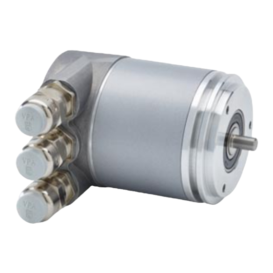
Hinweise gültig für folgende Typen:
Synchroflansch
6FX2001-5FP12
Auflösung: 13 Bit (Singleturn)
6FX2001-5FP24
Auflösung: 13 + 14 Bit (Multiturn)
Notes: 1.) Only CYJV2/8 cables shall be used for the connection to the connectors. 2.) Only cables recognized in AVLV2/8 shall be used for the
connection to the cable glands. The diameter of these cables shall be within the clamping range of the cable gland.
3.) All used cables shall have appropriate temperature, voltage and current ratings.
4.) The product shall be used in NFPA 79 Applications only.
5.) Adapters providing field wiring means are available from the manufacturer. Refer to the product manual or contact the customer support.
Hinweise zum mechanischen Einbau und elektrischen An-
schluss des Absolutwertgebers
Den Absolutwertgeber nicht fallen lassen oder größeren Erschütterungen aus-
setzen. Es handelt sich um ein Präzisionsmessgerät.
Das Absolutwertgebergehäuse nicht öffnen (bezieht sich nicht auf das Abneh-
men der Haube). Unsachgemäßes Öffnen bzw. Schließen des Gerätes kann
Schäden und Verschmutzungen verursachen.
Die Welle des Gebers muss über eine geeignete Kupplung mit der zu mes-
senden Welle verbunden werden. Diese Kupplung dient dazu, Schläge und
Unwuchten zu dämpfen und unzulässig hohe Kräfte auf die Welle des Codie-
rers zu vermeiden. Geeignete Kupplungen sind als Zubehör erhältlich (siehe
Katalog NC Z). Die zulässigen Axial- bzw. Radialbelastungen der Welle dürfen
nicht überschritten werden (siehe „Mechanische Daten")!
Die MC-ENCODER Absolutwertgeber sind robust, sollten aber in sehr rauem
Umfeld durch geeignete Schutzmaßnahmen vor Beschädigung geschützt
werden. Insbesondere sollten sie nicht so eingebaut werden, dass sie sich als
Haltegriffe oder Trittstufen eignen.
Inbetriebnahme und Betrieb dieses elektrischen Gerätes dürfen nur von qua-
lifiziertem Personal vorgenommen werden. Dies sind Personen mit der Be-
rechtigung Geräte, Systeme und Stromkreise gemäß dem Stand der Sicher-
heitstechnik in Betrieb zu nehmen, zu erden und zu kennzeichnen.
Am Absolutwertgeber dürfen keine elektrischen Veränderungen vorgenom-
men werden.
Anschlussleitung zum Winkelcodierer in großem Abstand, oder räumlich ab-
getrennt, von mit Störungen belasteten Energieleitungen verlegen. Zur siche-
ren Datenübertragung müssen komplett geschirmte Kabel benutzt und auf
eine gute Erdung geachtet werden.
Verdrahtungsarbeiten, Öffnen und Schließen von elektrischen Verbindungen
nur im spannungslosen Zustand durchführen. Kurzschlüsse, Spannungsspit-
zen u.ä. können zu Fehlfunktionen und zu unkontrollierten Zuständen bzw. zu
erheblichen Personen- und Sachschäden führen. Vor Einschalten der Anlage
alle elektrischen Verbindungen überprüfen. Nicht korrekt vorgenommene Ver-
bindungen können zur Fehlfunktion der Anlage, falsche Verbindungen zu er-
heblichen Personen- und Sachschäden führen.
Achtung:
Die Anschlusshaube darf nicht unter Spannung gesteckt oder gelöst werden!
MC-ENCODER
Stand 05/19
Klemmflansch
6FX2001-5QP12
6FX2001-5QP24
99998061
Instructions are valid for following types:
Synchro flange
6FX2001-5FP12
Resolution: 13 bits (singleturn)
6FX2001-5FP24
Resolution: 13 + 14 bits (multiturn)
Instructions to mechanically install and electrically connect
Do not drop the angular encoder or subject it to excessive vibration. The
encoder is a precision device. Do not open the angular encoder housing
(this does not mean that you cannot remove the connection cap). If the
device is opened and closed again, then it can be damaged and dirt may
enter the unit. The angular encoder shaft must be connected to the shaft
to be measured, through a suitable coupling. This coupling is used to
dampen vibrations and to correct imbalance on the encoder shaft and
also avoid unacceptably high forces (refer to „Mechanical Data"). Suita-
ble couplings are available as an accessory, refer to catalog NC Z.
Although MC-ENCODER absolute value encoders are rugged, when
used in tough ambient conditions, they should be protected against dam-
age using suitable protective measures. Care should be taken that they
are not installed so that they can be used as handles or even steps.
Only qualified personnel may commission and operate these devices.
These are personnel who are authorized to commission, ground and tag
devices, systems and circuits according to the current state of safety
technology.
It is not permissible to make any electrical changes to the encoder.
Route the connecting cable to the angular encoder at a considerable dis-
tance away or completely separated from power cables with their asso-
ciated noise. Completely screened cables must be used for reliable data
transfer and good grounding must be provided.
Cabling, establishing and interrupting electrical connections may only be
carried-out when the equipment is in a no-voltage condition. Short-cir-
cuits, voltage spikes etc. can result in erroneous functions and uncon-
trolled statuses which can even include severe personal injury and ma-
terial damage.
Before powering-up the system, check all of the electrical connections.
Connections, which are not correct, can cause the system to function in-
correctly and fault connections can result in severe personnel injury and
material damage.
Caution:
Do not remove or mount the connection cap while the encoder is under
power!
99998061
Seite / Page 1
Clamp flange
6FX2001-5QP12
6FX2001-5QP24
the angular encoder
Werbung

Verwandte Anleitungen für Siemens MC-ENCODER


Inhaltszusammenfassung für Siemens MC-ENCODER
- Seite 1 If the pertinent documentation is not in your hands, please send for it using the order number indicated in the respective product catalog or contact your local SIEMENS office. Only properly trained staff aware of local safety regulations are allowed to commission and operate, or to work on and around this product after procedures contained in the documentation.
- Seite 2 Beiblatt / Description Seite / Page 2 Stand 05/19 Diagnosemeldungen durch die LEDs der Anschlusshaube / Meaning of the LEDs in the connection cap Rote LED / Grüne LED / Bedeutung / Red LED Green LED Meaning aus / off aus / off Spannungsversorgung fehlt / No power supply...
- Seite 3 IP 67 Wellenseite / Shaft Side IP 64 Das Benutzerhandbuch ist separat erhältlich unter: The user manual is available separately under: https://support.industry.siemens.com/ https://support.industry.siemens.com/ Suchbegriff: Absolutwertgeber Profibus-DP Search criteria: "Measuring systems with Profibus DP" Maßzeichnungen / Mechanical Drawing Synchroflansch / Synchro flange...
- Seite 4 Beiblatt / Description Seite / Page 4 Stand 05/19 Klemmflansch / Clamp flange Montagevorschläge / Mounting suggestions Synchroflansch / Synchro flange Spannpratze / Clamp 6FX2001-7KP01 *M3 Md = 1.1 - 1.3 Nm, **M4 Md = 2.4 - 2.9 Nm Metrische Regelgewinde nach DIN 13, Festigkeitsklasse 8.8 / Metric standard thread according to DIN 13, strength class 8.8 Klemmflansch / Clamp flange = 2,4 –...