Inhaltsverzeichnis
Werbung
TH 02 / 02-Ex / 02-Ex N
TH 102 / 102-Ex / 102-Ex N
TH 202 / 202-Ex / 202-Ex N
Gebrauchsanweisung / Manual
TH 02
Diese Gebrauchsanweisung muß mit dem zu-
gehörigen Listenblatt und bei explosionsge-
schützten Geräten außerdem mit der zugehö-
rigen PTB-Bescheinigung ergänzt werden
(siehe Seite 2).
HART-programmierbare
Temperatur-Transmitter
HART programmable
temperature transmitters
42/11-49 XA
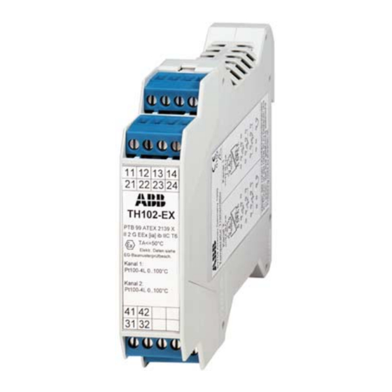
TH 102
This Manual may only be used with the Data
Sheet for the device (see page 3) or (for explo-
sion protected devices) with the data Sheet for
the device and with the EEC Certificate of
Conformity or Declaration of Conformity for the
device (see page 3).
TH 202
Rev. 1.0
Werbung
Inhaltsverzeichnis

Verwandte Anleitungen für ABB TH 02


Inhaltszusammenfassung für ABB TH 02
- Seite 1 TH 02 / 02-Ex / 02-Ex N HART-programmierbare TH 102 / 102-Ex / 102-Ex N Temperatur-Transmitter TH 202 / 202-Ex / 202-Ex N HART programmable temperature transmitters Gebrauchsanweisung / Manual 42/11-49 XA Rev. 1.0 TH 02 TH 102 TH 202 Diese Gebrauchsanweisung muß...
-
Seite 2: Allgemeine Sicherheitshinweise
TH 02-Ex N, TH 102-Ex N und TH 202-Ex N dürfen direkt in Zone 2 montiert werden. TH 02-Ex N, TH 102-Ex N und TH 202-Ex N so montieren, daß auch für die Anschlußteile ein Gehäuseschutzgrad von mindestens IP 54 gemäß... -
Seite 3: General Safety Regulations
TH 02-Ex N, TH 102-Ex N and TH 202-Ex N may be directly mounted in Zone 2. TH 02-Ex N, TH 102-Ex N and TH 202-Ex N should be mounted in such way that a degree of protection of at least IP 54 to IEC publication 529 (144) is also maintained for connected elements. - Seite 4 TH 02 / -Ex / -Ex N montieren Mounting TH 02 / -Ex / -Ex N Bild 1 TH 02 / -Ex / -Ex N montieren Fig. 1 Mounting TH 02 / -Ex / -Ex N links Maßbild (Maße in mm)
- Seite 5 Sensor and supply conduits are connected to the screw klemmen des TH 02 / -Ex / -Ex N für Leitungsquerschnitte bis terminals of TH 02 / -Ex / -Ex N for pipe cross-sections of up max. 1,5 mm² (mit Adernendhülsen) angeschlossen.
-
Seite 6: Montagemö Glichkeiten
Montagemö glichkeiten Standard-Ausfü hrung (h = 22,5 mm) Standard-Ausfü hrung (h = 22,5 mm) fü r Montage auf Meß einsätzen ohne angenietete Anschluß kopf BUZH Hü lsen und Federn (z.B. Anschluß kopf DIN-B) Anschlußdrähte des Meßeinsatzes ca. 50 mm lang und isoliert. Bild 3 Standard-Ausführung montieren Bild 5... -
Seite 7: Mounting Possibilities
Mounting possibilities Standard version (h = 22.5 mm) Standard version (h = 22.5 mm) for mounting on measuring modules withoout riveted Connection head BUZH sleeves and springs (e.g. connection head DIN-B) Connection wires of measuring modules approx. 50 mm long and insulated. - Seite 8 TH 102 / -Ex / -Ex N montieren Mounting TH 02 / -Ex / -Ex N Bild 11 TH 102 / -Ex / -Ex N montieren Fig. 11 Mounting TH 102 / -Ex / -Ex N links Maßbild (Maße in mm), Breite 22,5 mm...
- Seite 9 TH 102 / -Ex / -Ex N anschließ en Wiring TH 102 / -Ex / -Ex N Bild 12 Anschlußbild Fig. 5 Connection diagram Widerstandsthermometer 2-Leiter Resistance thermometer 2-wire Widerstandsthermometer 3-Leiter Resistance thermometer 3-wire Widerstandsthermometer 4-Leiter Resistance thermometer 4-wire Doppelwiderstandsmessung 2-Leiter Double resistance measurement 2-wire Differenztemp.
- Seite 10 TH 202 / -Ex / -Ex N montieren Mounting TH 02 / -Ex / -Ex N Bild 13 TH 202 / -Ex / -Ex N montieren Fig. 13 Mounting TH 202 / -Ex / -Ex N links Maßbild (Maße in mm) links Maßbild (Maße in mm)
- Seite 11 TH 202 / -Ex / -Ex N anschließ en Wiring TH 202 / -Ex / -Ex N Bild 14 Anschlußbild Fig. 5 Connection diagram Widerstandsthermometer 2-Leiter Resistance thermometer 2-wire Widerstandsthermometer 3-Leiter Resistance thermometer 3-wire Widerstandsthermometer 4-Leiter Resistance thermometer 4-wire Doppelwiderstandsmessung 2-Leiter Double resistance measurement 2-wire Differenztemp.
-
Seite 12: Mit Pc Programmieren
= 22 mA müssen mindestens 8,5 V an den Klemmen des Transmitters zur Verfügung stehen Busbetrieb Mit PC programmieren TH 02, TH 02-Ex, TH 102 und TH 102-Ex sind für Multitrop- und Software FSK-Bus-Betrieb geeignet. SMART VISISON (vom Hersteller zu beziehen) - Seite 13 8.5 V must be available at the transmitter terminals. Bus operation Programming with PC TH 02, TH 02-Ex, TH 102 and TH 102-Ex are suitable for multi- Software trop and FSK bus operation. SMART VISISON (to be ordered from manufacturer)
-
Seite 14: Gemeinsame Speisung Mehrerer Geräte
Form der Speicherung in Datenverarbeitungs- anlagen oder Datennetzen ohne Genehmigung des Rechteinha- bers sind untersagt und werden zivil- und strafrechtlich verfolgt. Bild 15 Gemeinsame Speisung: mehrere TH 02 / TH 102 (einka- nalig) / TH 202 Bild 16 Gemeinsame Speisung: mehrere TH 102 (zweikanalig) Imax = n ×...