Anmelden
Hochladen
Anleitungen
Marken
Ametek Anleitungen
Steuergeräte
dunkermotoren BGE 6060 A
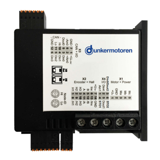
Ametek dunkermotoren BGE 6060 A Handbücher
Anleitungen und Benutzerhandbücher für Ametek dunkermotoren BGE 6060 A. Wir haben
2
Ametek dunkermotoren BGE 6060 A Anleitungen zum kostenlosen PDF-Download zur Verfügung: Betriebsanleitung
Ametek dunkermotoren BGE 6060 A Betriebsanleitung (65 Seiten)
Marke:
Ametek
| Kategorie:
Steuergeräte
| Dateigröße: 3.96 MB
Inhaltsverzeichnis
English
2
Inhaltsverzeichnis
2
About this Document
6
Über dieses Dokument
6
General Description
7
Series
7
Allgemeine Beschreibung
7
Baureihe
7
Explanation of Terms Used
8
Begriffserklärung
8
Proper Use
9
Bestimmungsgemäße Verwendung
9
Current Characteristics
13
Stromkennlinien
13
Starter Kit (Accessory)
14
Starter Kit (Zubehör)
14
Types of Operation
15
Slave in Canopen Networks
15
Betriebsarten
15
Slave in Canopen Netzwerken
15
Power Supply and Motor Connections
19
Versorgungsspannung und Motoranschluss
19
Hall Sensors/Encoders & Analog and Digital
20
Inputs and Outputs
20
Hallsensoren/Encoder & Analoge und Digi- Tale Ein- und Ausgänge
20
EMC-Compliant Installation
21
EMV-Gerechte Installation
21
Connection Brushless Motor
22
Connection Brushed Motor
22
Anschluss Bürstenloser Motor
22
Anschluss Bürstenbehafteter Motor
22
Connection Hall Sensors
23
Connection Encoder
23
Anschluss Hallsensoren
23
Anschluss Encoder
23
Connection Power Supply / Grounding
24
Connection Electronics / Controller Enabling (STO)
24
Anschluss Spannungsversorgung / Erdung
24
Anschluss Elektronik / Reglerfreigabe (STO)
24
Connection CAN Interface
25
Blockschaltbild
25
Digital Inputs
26
Digital Outputs
26
Digitale Eingänge
26
Hilfsspannungen
27
Status Leds
28
Maintenance & Service & Support
29
Maintenance, Taking out of Service and Dis- Posal
29
Service & Support
29
Declaration of Conformity
29
Wartung & Service & Support
29
Wartung, Außerbetriebsetzung und Entsor- Gung
29
Konformitätserklärung
29
Commissioning
30
Stand Alone Operation
30
Inbetriebnahme
30
System Requirements
30
Stand Alone Betrieb
30
Installation of Software Drive Assistant
30
Systemvoraussetzungen
30
Installation Software Drive Assistant
30
Description of Main Window
31
Projektfenster
31
Short Description of PI Modules
32
PI 100 Positioning Module „Standard
32
Kurzbeschreibung PI Module
32
PI 110 Positioning Module „Stepper
33
PI 120 Positioning Module „Left-Right
34
PI 130 Positioning Module „Modulo
35
PI 140 Positioning Module
36
Complete Positioning Command
36
PI 150 Positioning Module
37
Positioning by Event
37
PI 200 Velocity Module
38
Velocity Mode Standard
38
PI 201 Velocity Module
39
Velocity Mode Multi
39
PI 200 Velocity Module
39
PI 300 Current Module
40
Current Mode Standard
40
PI 301 Current Module
41
Current Mode Multi
41
Slave in Canopen
42
Hardware Controller
42
Mplc Introduction
43
Documentation
43
Mplc System Requirements
44
Installation of the Software Mplc
44
Installation CAN-USB Adapter
44
Mplc Control Center
45
Python Script
46
CAN Monitor
49
Configuration
51
Objects
53
Objects / SDO-Variable
53
Set up CAN Objects
55
Set up CAN Variables
56
Transmit / Receive
58
Recording
58
CAN Master of Other Manufacturers
60
Communication Settings
61
Standard Variant - LMT Services
61
Manufacturer Specific Variant
62
Test Programs and Other Assistance
63
German
9
Standards and Guidelines
9
Zertifikate/ Konformitäten
9
Safety Instructions
10
Sicherheitshinweise
10
Technical Data, Accessories
11
General Performance Data
11
Technische Daten, Zubehör
11
Allgemeine Leistungsdaten
11
General Features
12
Allgemeine Eigenschaften
12
Dimensions
14
Maßzeichnung
14
Stand-Alone Operation at Stored Running
16
Profile
16
Stand-Alone Betrieb mit Gespeichertem
16
Fahrprofil
16
Installation
17
Terminal Assignment
18
Anschlussbelegung
18
Block Diagram
25
Anschluss CAN Schnittstelle
25
Digitale Ausgänge
26
Analog Inputs
27
Inputs for Hall Sensors
27
Inputs for Encoders
27
Auxiliary Power Supply
27
Analoge Eingänge
27
Eingänge für Hallsensoren
27
Eingänge für Encoder
27
Project Window
31
Beschreibung des Hauptfensters
31
Hardware Regler
42
Mplc Einführung
43
Dokumentation
43
Mplc Systemvoraussetzungen
44
Installation der Software Mplc
44
Konfiguration
51
Objekte
53
Objekt- / SDO-Variable
53
Anlegen von CAN-Objekten
55
Anlegen von CAN-Variablen
56
Senden / Empfangen
58
Aufzeichnen
58
CAN-Master anderer Hersteller
60
Kommunikationseinstellungen
61
Standardvariante -LMT Dienste
61
Herstellerspezifische Variante
62
Testprogramme und Weitere Hilfsmittel
63
Werbung
Ametek dunkermotoren BGE 6060 A Betriebsanleitung (32 Seiten)
Marke:
Ametek
| Kategorie:
Steuergeräte
| Dateigröße: 2.31 MB
Inhaltsverzeichnis
English
2
Inhaltsverzeichnis
2
About this Document
5
Über dieses Dokument
5
General Description
6
Allgemeine Beschreibung
6
Series
6
Explanation of Terms Used
6
Baureihe
6
Begriffserklärung
6
Service Data Object (SDO)
7
Servicedatenobjekt (SDO)
7
Process Data Object (PDO)
8
Proper Use
8
Prozessdatenobjekt (PDO)
8
Bestimmungsgemäße Verwendung
8
Current Characteristics
12
Stromkennlinien
12
Starter Kit (Option)
13
Types of Operation
14
Betriebsarten
14
Dunkermotoren Specific Control „Quick-Start
14
Dunkermotoren Spezifische Ansteuerung „Quick-Start
14
Operation Modes According to Cia DS402 (en 61800-7-201:2008)
14
Betriebsmodi nach Cia DS402 (en 61800-7- 201:2008)
14
Twincat System
15
Power Supply and Motor Connections
18
Hall Sensors/Encoders & Analog and Digital Inputs and Outputs
18
Versorgungsspannung und Motoranschluss
18
Hallsensoren/Encoder & Analoge und Digi- Tale Ein- und Ausgänge
18
EMC-Compliant Installation
20
EMV-Gerechte Installation
20
Connection Brushless Motor
21
Anschluss Bürstenloser Motor
21
Connection Brushed Motor
21
Anschluss Bürstenbehafteter Motor
21
Connection Hall Sensors
22
Connection Encoder
22
Anschluss Hallsensoren
22
Anschluss Encoder
22
German
7
Ethercat Specific Explanations
7
Canopen over Ethercat (Coe)
7
Ethercat Spezifische Begriffe
7
Standards and Guidelines
8
Zertifikate/ Konformitäten
8
Safety Instructions
9
Sicherheitshinweise
9
Technical Data, Accessories
10
General Performance Data
10
Technische Daten, Zubehör
10
Allgemeine Leistungsdaten
10
General Features
11
Allgemeine Eigenschaften
11
Dimensions
13
Maßzeichnung
13
Non Supported Functions
15
Nicht Unterstützte Funktionen
15
Installation
16
Terminal Assignment
17
Anschlussbelegung
17
Connection Power Supply / Grounding
23
Connection Electronics / Controller Enabling
23
Anschluss Spannungsversorgung / Erdung
23
Anschluss Elektronik / Reglerfreigabe
23
Connection CAN Interface (Only for Service)
24
Block Diagram
24
Anschluss CAN Schnittstelle (nur für Service)
24
Blockschaltbild
24
Digital Inputs
25
Digital Outputs
25
Digitale Eingänge
25
Digitale Ausgänge
25
Analog Inputs
26
Inputs for Hall Sensors
26
Inputs for Encoders
26
Auxiliary Power Supply
26
Analoge Eingänge
26
Eingänge für Hallsensoren
26
Eingänge für Encoder
26
Hilfsspannungen
26
Status Leds
27
Commissioning
29
Inbetriebnahme
29
ESI File
29
Documentation
29
ESI-Datei
29
Dokumentationen
29
Maintenance & Service & Support
30
Maintenance, Taking out of Service and Dis- Posal
30
Service & Support
30
Declaration of Conformity
30
Wartung & Service & Support
30
Wartung, Außerbetriebsetzung und Entsor- Gung
30
Konformitätserklärung
30
Werbung
Verwandte Produkte
Ametek dunkermotoren BGE 6005 A
Ametek dunkermotoren BGE 6010 A
Ametek dunkermotoren BGE 6015 A
Ametek dunkermotoren BGE 3004A
Ametek dunkermotoren BGE 42
Ametek dunkermotoren BGE 5510 dPro IO/CO
Ametek dunkermotoren BG 32 dCore
Ametek dunkermotoren BG 65S dCore
Ametek dunkermotoren BG 66x75 dMove
Ametek dunkermotoren BG 65x50 dMove
Ametek Kategorien
Motoren
Messgeräte
Laborzubehör & Laborgeräte
Steuergeräte
Generatoren
Weitere Ametek Anleitungen
Anmelden
Anmelden
ODER
Mit Facebook anmelden
Mit Google anmelden
Anleitung hochladen
Von PC hochladen
Von URL hochladen