Herunterladen Inhalt Inhalt Diese Seite drucken
Inhaltsverzeichnis

Werbung

Verfügbare Sprachen

Verfügbare Sprachen

ASSEMBLY AND OPERATION MANUAL
BV-5-868 Boom Barrier
MONTAGE-UND BETRIEBSANLEITUNG
Schranke BV-5-868
MANUEL D'INSTALLATION ET D'UTILISATION
Barrière levante BV-5-868
ENGLISH
DEUTSCH
FRANÇAIS
05.2020
www.alutech-group.com

Werbung

Inhaltsverzeichnis
loading

Inhaltszusammenfassung für Alutech BV-5-868

  • Seite 1 ASSEMBLY AND OPERATION MANUAL ENGLISH BV-5-868 Boom Barrier MONTAGE-UND BETRIEBSANLEITUNG DEUTSCH Schranke BV-5-868 MANUEL D’INSTALLATION ET D’UTILISATION FRANÇAIS Barrière levante BV-5-868 05.2020 www.alutech-group.com...
  • Seite 3: Inhaltsverzeichnis

    Information on repairs during warranty period ....... BOOM BARRIER BV-5-868...
  • Seite 4: Warnings And Safety Rules

    Loading, unloading, assembly and disassembly of the barrier must be carried out in accord- ance with safety regulations taking into account the weight of the barrier. The barrier shall be assembled by two persons. BOOM BARRIER BV-5-868...
  • Seite 5 (EN 12453, EN 12604) must be ensured by installing safety devices, safeguards, and observing safe distances and clearances. When operating outside the barrier visibility area or when automatic barrier closing is activated in the settings, photocells (or equivalent safety device) must be installed. BOOM BARRIER BV-5-868...
  • Seite 6: When Operating The Device

    The barrier system and the barrier shall be subject to scheduled maintenance to ensure efficient and safe operation. Maintenance and repairs should be documented by the persons performing them, and the owner should keep these records. Do not use the barrier if it needs repair! BOOM BARRIER BV-5-868...
  • Seite 7: Product Description

    PRODUCT DESCRIPTION PRODUCT DESCRIPTION BV-5-868 electromechanical barrier is designed to automatically restrict entry / exit of vehicles to / from a certain territory. When equipped with a RBN8 boom profile, the roadway width is limited to 5 m. When equipped with a RBN6-K (optional) boom profile, the roadway width is limited to 6 m.
  • Seite 8 (section ‘7.2. Setting operation parameters’ P6–F1 and P6–F2) Unstable power line voltage; voltage surges Ambient temperature above +40 °С and below 0 °С Presence of sand and dust (sand or dust storms), salt mist, etc. High wind load (> 20 m / s) BOOM BARRIER BV-5-868...
  • Seite 9: Preparation For Assembly

    (Fig. 9). Installing the barrier cabinet. Use the key to open the door lock, remove the barrier door (Fig. 10) and carefully put it aside. Install the cabinet and secure it with the nuts and washers. (Fig. 11). BOOM BARRIER BV-5-868...
  • Seite 10: Installing The Spring

    Turn the lever 90° and install it back. (Fig. 17). Find the correct opening on the spring lever (see Table 3) and secure the spring to the lever (Fig. 18). Connect the spring to the barrier cabinet at the bottom (Fig. 19). BOOM BARRIER BV-5-868...
  • Seite 11: Installing A Rbn8 Boom

    • Move the boom to 45° position and rotate the spring (Fig. 27) until the boom remains still in this position. • Make sure the balancing is complete by moving the boom from its end positions to the middle position several times. Tighten the spring nut (Fig. 26). BOOM BARRIER BV-5-868...
  • Seite 12: Adjusting The Boom Position

    If the direction of motion is wrong, switch off the mains supply and swap the motor connection wires at the M1 and M2 terminals of the control unit (Fig. 37, terminal block 13). Then check again the direction of motion of the boom (Fig. 35, Fig. 36). BOOM BARRIER BV-5-868...
  • Seite 13: Electrical Connections

    Incorrect connection may result in product failure. Use additional devices (accessories) offered by ALUTECH and with the required characteristics. ALUTECH is not responsible for the unstable operation of the boom barrier system when using accessory devices manufactured by other manufacturers.
  • Seite 14 Supply voltage output –U of LED boom is selected in the settings (section backlighting (green light) ‘7.2. Setting operation parameters’ P8–F5 and P8–F6). Green light turns Supply voltage output –U of LED boom on when fully open backlighting (red light) BOOM BARRIER BV-5-868...
  • Seite 15 End position switch CLOSED input with normally closed contact (NC) ~24 * ~12 * Inputs for secondary coil leads of control unit transformer ~0 * M2 * Outputs for connection of the barrier motor leads M1 * * Connections are performed by manufacturer on delivery. BOOM BARRIER BV-5-868...
  • Seite 16: Setup

    The displayed value will appear with a dot, indicating that the setting has changed To exit the setup menu, press button (2–3 times) until the dot × 2–3 appears on the display. In standby mode, the setup menu will be automatically exited after 10 minutes BOOM BARRIER BV-5-868...
  • Seite 17: Radio Control Setup

    OPEN (ENTRY) terminal blocks 5–8 (Table 4) to oper- OPEN ate two-way regulation (P3–F4…F7 OPEN (EXIT) settings, Table 15), ENTRY or EXIT direction is MASTER barrier control during determined synchronized operation mode / P9 setting, Table 15 CLOSE CLOSE Closing operation BOOM BARRIER BV-5-868...
  • Seite 18 № 1 or № 2 (settings P3–F4…F7, Table 15). LOAD Automatic disabling (operation LOAD № 2 (ON) time) of the load is set by P8–F7 (LOAD № 1) and P8–F8 (LOAD № 2) settings LOAD № 2 (OFF) LOAD № 2 (ON / OFF) BOOM BARRIER BV-5-868...
  • Seite 19 ×3 In ~2 s the system will automatically switch to recording the next remote control (repeat steps 3 to 5). To exit setup menu, press button 3 times BOOM BARRIER BV-5-868...
  • Seite 20 (e.g., number 01.). In ~2 s the system will automatically switch to recording the next remote control ×3 with a preset combination of b1–b4 buttons (repeat steps 7 to 9). To exit setup menu, press button 3 times BOOM BARRIER BV-5-868...
  • Seite 21: Editing The Commands Recorded In A Remote Control

    Repeat steps 5 and 6 for control buttons b2, b3, b4 ×2 Once the command selected for b4 button is confirmed by pressing button, the display will show F4. To exit setup menu, press button twice BOOM BARRIER BV-5-868...
  • Seite 22 After ~2 s, the system will automatically switch to waiting for the remote ×3 control signal. If necessary, edit the button command on this or another recorded remote control (repeat steps 3 to 6). To exit setup menu, press button 3 times BOOM BARRIER BV-5-868...
  • Seite 23 In 2 s, the system will automatically switch to waiting for a signal from the remote control. The display will show rc. You may now proceed to deleting the next remote control (repeat steps 3 to 5) ×3 To exit setup menu, press button 3 times BOOM BARRIER BV-5-868...
  • Seite 24 After dL appears on display, press button and hold for ~5 s until a dot appears on display, meaning that all remotes have been deleted from memory ×2 After F0 appears on display, press button twice to exit setup menu BOOM BARRIER BV-5-868...
  • Seite 25: Setting Operation Parameters

    (values 05 and 06, Table 16), the SBS input can be used for the ENTRY direction, the OP input OP OPEN for the EXIT direction. STEP-BY-STEP or OPEN 03 — SBS step-by-step commands correspond to those of the remote OP OPEN control. (Table 6) BOOM BARRIER BV-5-868...
  • Seite 26 (Fig. 37, terminal block 4). inputs Fig. 40 — Connection of photocells to PH1 input: diagram example PHOTOTEST feature cannot be disabled (no) if automatic closing is enabled (pause time set in P4–F1 and / or P4–F2 settings) BOOM BARRIER BV-5-868...
  • Seite 27 Barrier LED signal operation. Select the op- no — disabled eration mode of the built-in LED barrier lamp 01 — enabled red light and boom backlight (Fig. 37, terminal block 9) 02 — enabled red and green light BOOM BARRIER BV-5-868...
  • Seite 28 (P3–F4…F7), the terminal outputs (relay contacts of the control unit) will operate in accordance with preset logic. The following figure shows the normal state of the outputs (relay contacts of the control unit). 5–8 NO — normally open contact NC — normally closed contact BOOM BARRIER BV-5-868...
  • Seite 29 Operation starts at the beginning of the set movement delay time (P7–F6 setting, Table 15) and continues operating until closed end position switch is off (or during 2 s). Fig. 49 — еxample of an electromechanical lock connection BOOM BARRIER BV-5-868...
  • Seite 30: Actory Reset

    (maximum 999 999 cycles). Example: — counter showing 123 456 cycles. Table 18 Press and hold button for ~5 s to enter setup menu When P1 appears, press button When P0 appears, press button BOOM BARRIER BV-5-868...
  • Seite 31: Two-Way Traffic Signalization

    When the traffic light is green driving through the open gate is permitted. The barrier will close automatically after a preset delay time is out. Recording the OPEN command into the remote controls provides only opening of the gate while operating a remote control. BOOM BARRIER BV-5-868...
  • Seite 32: Indication

    (OP.L input, terminal block 12) Terminal block 7 outputs status enabled in settings ( subsection ‘7.2. Setting operation parameters’ P3–F6). LLK1 LED light is off when the terminals are in normal condition and is ON when the terminals are activated. BOOM BARRIER BV-5-868...
  • Seite 33 Safety edge activated (SE input, terminal block 4) Error occurred during PHOTOTEST (sub-section ‘7.2. Setting operation parameters’ P7–F3) STOP security device activated (S input, terminal block 4) Synchronized operation error (sub-section ‘7.2. Setting operation parameters’ P9–F1) Movement interruption at work time end BOOM BARRIER BV-5-868...
  • Seite 34: Functional Check And Start-Up Operations

    Do not allow partial or temporary start-up. • Prepare and store the technical documentation for the automatic performance package. The documentation must contain: assembly and operating manual, maintenance schedule, diagram of the boom barrier system and electrical cabling. BOOM BARRIER BV-5-868...
  • Seite 35: Service And Maintenance

    After the end of the service lifetime or expected life of the product, a specialist should assess the possibility of further operation and the need for repair (replacement of the most critical parts, such as the counterbalance spring, gearbox, electric motor, control unit, etc.). BOOM BARRIER BV-5-868...
  • Seite 36: Troubleshooting Guide

    The barrier does not react to The photocells are out Check the photocells and replace an obstacle on the photocells of order if necessary optical axis when closing BOOM BARRIER BV-5-868...
  • Seite 37: Storage, Transportation, And Disposal

    − failure to provide a completed manual. You can find service information at the following link: http://www.alutech-group.com / feedback / service/ Product conformity documents (certificates / declarations) are available at the following link: https://alutech-group.com / product / shlagbaumy / avtomaticheskie-shlagbaumy / DOCUMENTS/ BOOM BARRIER BV-5-868...
  • Seite 38: Commisioning Certificate

    The user was instructed on the existing hazards and risks, and informed about operation rules. Information about the client (customer) name, address and telephone number Customer's signature (owner) signature full name BOOM BARRIER BV-5-868...
  • Seite 39: Information On The Work Performed

    The table below is used to record the operations carried out during installation and operation of the product: data of the barrier boom, connected optional devices, safety devices, adjustments performed (other than factory values), inspections, maintenance, modifications, etc. SPECIALIST'S OWNER'S DATE OPERATION PERFORMED SIGNATURE SIGNATURE BOOM BARRIER BV-5-868...
  • Seite 40: Information On Repairs During Warranty Period

    Made in China Importer to the Republic of Belarus/ Authorized representative of the manufacturer: ALUTECH Systems s.r.o., 348 02, Czech Republic, Bor u Tachova, CTPark Bor, Nova Hospoda 19, D5-EXIT 128 Phone/ fax: +420 374 6340 01 e-mail: info@cz.alutech-group.com BOOM BARRIER BV-5-868...
  • Seite 41 ..........Reparaturen im Rahmen der Garantieverpflichtungen ......SCHRANKE BV-5-868...
  • Seite 42: Sicherheits-Und Warnhinweise

    Toleranzgrenzen liegen (Kapitel "2,2. Technische Daten"). Der Installationsort muss dem angegebenen Temperaturbetriebsbereich entsprechen, der auf der Kennzeichnung der Schranke angegeben ist. Es ist erforderlich, die Auswirkungen von den im Einsatzort (Region) vorherrschenden Windlasten auf den Betrieb der Schranke zu bewerten. Der Schrankenbaum-Satz muss richtig ausgewählt sein. SCHRANKE BV-5-868...
  • Seite 43 Die Kabel sind gegen den Kontakt mit rauen und scharfen Ober- flächen zu schützen. Verwenden Sie beim Verlegen von Kabeln Wellschläuche, Rohre und Ka- beleinführungen. Verwenden Sie eine doppelt isolierte Kupferleitung für den Anschluß der Schrankenanlage-Komponenten. SCHRANKE BV-5-868...
  • Seite 44: Im Betrieb

    Das Produkt ist nicht zur Verwendung in sauren, salzigen oder explosionsgefährdeten Bereichen vorgesehen. In der Schranke, Steuereinheit und in anderen elektrischen Geräten der Schrankenanlage dürfen sich keine Fremdkörper und Materialien von Bauarbeiten befinden. Dort darf kein Wasser oder andere Flüssigkeit vorhanden sein. Der Anlagenbetrieb ist in diesem Zustand verboten. SCHRANKE BV-5-868...
  • Seite 45 Die Schrankenanlage und die Schranke sind routinemäßig zu warten, um einen effizienten und sicheren Betrieb zu gewährleisten. Wartung und Reparaturen müssen von den ausführenden Personen dokumentiert werden und der Betreiber muss diese Dokumente aufbewahren. Verwenden Sie die reparaturbedürftige Schranke nicht! SCHRANKE BV-5-868...
  • Seite 46: Produktbeschreibung

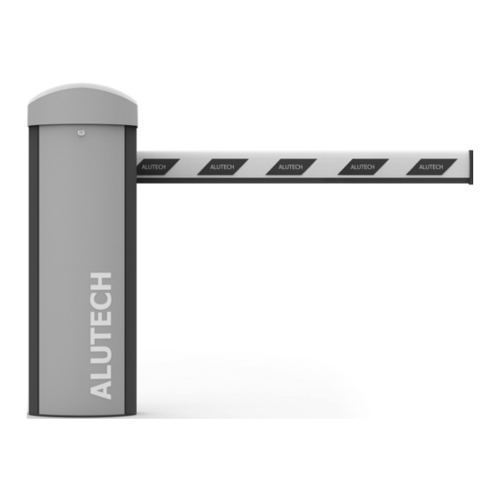
    PRODUKTBESCHREIBUNG PRODUKTBESCHREIBUNG Die elektromechanische Schranke BV-5-868 dient der automatischen Durchfahrtbeschränkung (Ein- / Ausfahrt) von Fahrzeugen. Bei Ausstattung der Schranke mit dem Schrankenbaum RBN8 ist die Fahrbahnbreite auf 5 m begrenzt. Bei Ausstattung der Schranke mit dem Schrankenbaum RBN6-К (optional) ist die Fahrbahnbreite auf 6 m begrenzt.
  • Seite 47 (Kapitel „7,2. Betriebswerte einstellen“) Wert der Bewegungsgeschwindigkeit in Einstellungen ist höher als 7 (Kapitel „7,2. Betriebswerte einstellen“ P6–F1 und P6–F2) Unregelmäßige Netzspannung, Netzspannungssprünge Umgebungstemperatur +40 °С und unter 0 °С Sand-und Staubbelastung (Sand-und Staubstürme), Salznebel etc. Erhöhte Windbelastung (> 20 m / s) SCHRANKE BV-5-868...
  • Seite 48: Montagevorbereitung

    Stellen Sie vor der Fundamenterhärtung sicher, dass die Grundplatte gerade und eben ist! Entfernen Sie von der Oberfläche der Grundplatte die Spuren von Beton und anderen Baumaterialien. Warten Sie, bis das Fundament erhärtet ist, und entfernen Sie dann die oberen Muttern und Unterlegscheiben (Abb. 9). SCHRANKE BV-5-868...
  • Seite 49: Feder Montieren

    Ausgangswelle (2) befestigt ist. Schrauben Sie die Federbefestigungsschraube (3) in den Hebel. Entfernen Sie den Hebel, indem Sie die Schraube langsam einschrauben (Abb. 16). Drehen Sie den Hebel um 90 ° und setzen Sie ihn wieder ein (Abb. 17). SCHRANKE BV-5-868...
  • Seite 50: Schrankenbaum Rbn8 Montieren

    Position zu heben, und die Kraft, die erforderlich ist, um den Schrankenbaum aus einer vertikalen Position zu senken, ungefähr gleich. Für die Ausgleichung sind zwei Mechaniker nötig. Der erste bewegt den Schrankenbaum und überwacht dessen Bewegung, der zweite stellt die Feder ein. SCHRANKE BV-5-868...
  • Seite 51: Schrankenbaum Einstellen

    Position. Die LED der Steuereinheit soll LCL.L anzeigen (Abb. 34). Sollten die LEDs verkehrt anzeigen, schalten Sie die Stromversorgung frei und wech- seln Sie an den Kontakten OP.L und CL.L der Steuereinheit (Abb. 37, Anschluß 12) die SCHRANKE BV-5-868...
  • Seite 52: Elektrische Anschlüsse

    Geräten gelieferten Anweisungen zu beachten. Ein falscher Anschluß kann zu Fehl- funktionen des Produkts führen. Setzen Sie zusätzliche Geräte (Zubehör) von ALUTECH mit den erforderlichen Eigenschaften ein. ALUTECH haften für den instabilen Betrieb der Schrankenanlage nicht, wenn zusätzliche Geräte von Dritten verwendet werden.
  • Seite 53 ANSCHLUSS KONTAKT BESCHREIBUNG +BAT Kontakte zum Anschluss einer speziellen ALUTECH-Einheit mit einem Lade- modul und einer 24-V-DC / 2,4-Ah-Batterie (Abb. 38). Die Batterieeinheit −BAT ermöglicht das Öffnen der Schranke im Notfallmodus (beim Stromausfall). Ladezeit des Akkus ~48 Stunden bei kontinuierlichem Betrieb der Schranke im Standby-Modus Eingang der Steuergeräte ÖFFNEN (Abb.
  • Seite 54 Erdanschluss der Endschalter CL.L * Endschalter-Eingang GESCHLOSSEN mit einem Öffnungskontakt (NC) ~24 * ~12 * Eingänge für Sekundärwicklung vom Transformator der Steuergerätes ~0 * M2 * Ausgänge des Schrankenbaum-Motors M1 * * Bei Auslieferung werden die Anschlüsse im Herstellerwerk hergestellt. SCHRANKE BV-5-868...
  • Seite 55: Einstellungen

    Es erscheint die Anzeige mit einem Punkt und das bedeutet die Abänderung des Einstellwertes Um das Einstellungsmenü zu verlassen, betätigen sie die Taste × 2–3 (2 bis 3-mal), bis die Anzeige mit einem Punkt erscheint. Im Standby-Modus wird das Einstellungsmenü selbsttätig in 10 Min. verlassen SCHRANKE BV-5-868...
  • Seite 56: Funksteuerung Einstellungen

    Anschlüssen 5–8 (Tabelle 4) wird für den Doppelverkehr (Einstel- ÖFFNEN ÖFFNEN lungen P3–F4…F7, Tabelle 15) die (AUSFAHRT) Richtung EINFAHRT bzw. AUSFAHRT festgelegt MASTER-Schrankenbaum- steuerung im Gleichlaufbe- trieb / Einstellung /Einstellung P9, Tabelle 15 SCHLIEßEN Ausführen der Schließbewegung SCHLIEßEN STOP STOP STOPP-Schritt ausführen SCHRANKE BV-5-868...
  • Seite 57: Beleuchtung

    № 1 bzw. № 2 (Einstellungen BELASTUNG P3–F4…F7, Tabelle 15). Die automa- BELASTUNG № 2 tische Abschaltung (Betriebszeit) der (EINSCHALTEN) Belastung wird durch Einstellungen P8–F7 (Belastung № 1) und P8–F8 BELASTUNG № 2 (Belastung № 2) eingestell (AUSSCHALTEN) BELASTUNG № 2 (EINSCHALTEN / AUSSCHALTEN) SCHRANKE BV-5-868...
  • Seite 58: Funksteuerung-Eintragung

    Eintragung zu bestätigen; nach Betätigung wird auf dem Display eine Ziffer mit Punkt angezeigt In ~2 s wechselt die Anzeige automatisch zur Eintragung der nächsten ×3 Fernbedienung (Schritte 3–5 wiederholen). Betätigen Sie dreimal die Taste , um das Einstellungsmenü zu verlassen SCHRANKE BV-5-868...
  • Seite 59 Display die Zahl mit Punkt angezeigt. (z.B., Zahl 01.) In ~2 s wechselt die Anzeige automatisch zur Eintragung der nächsten Fernbedienung mit vorgegebener Kombination von Tastenbefehlen ×3 (Schritte 7–9 wiederholen). Betätigen Sie die Taste dreimal, um das Einstellungsmenü zu verlassen SCHRANKE BV-5-868...
  • Seite 60: Befehlsänderung Der Eingetragenen Fernbedienung

    Display die Ziffer mit Punkt angezeigt Erkennung von Hindernissen durch integriertes Sicherheitssystem. Nachdem der ausgewählte Tastenbefehl b4 mit der Taste bestätigt ×2 worden ist, wird auf dem Display F4 angezeigt. Betätigen Sie die Taste zweimal, um das Einstellungsmenü zu verlassen SCHRANKE BV-5-868...
  • Seite 61 In ~2 s wechselt die Anzeige automatisch zum Warten auf das Fernbedienung-Signal. Nehmen Sie bei Bedarf die Befehlsänderung ×3 der Taste von dieser bzw. weiteren eingetragenen Fernbedienung vor (Schritte 3–6 wiederholen). Betätigen Sie die Taste dreimal, um das Einstellungsmenü zu verlassen SCHRANKE BV-5-868...
  • Seite 62: Anzahl Der Eingetragenen Fernbedienungen Feststellen

    Punkt und dies bedeutet Fernbedienung löschen. In ~2 s wechselt die Anzeige automatisch zum Warten auf das Fernbedienung-Signal. Auf dem Display wird rc angezeigt. Sie können eine andere Fernbedienung löschen (Schritte 3–5 wiederholen). ×3 Betätigen Sie die Taste dreimal, um das Einstellungsmenü zu verlassen SCHRANKE BV-5-868...
  • Seite 63: Alle Fernbedienungen Löschen

    Sie die Taste ~ 5 s lang gedrückt, bis ein Punkt auf dem Display angezeigt wird. Dies bedeutet, dass alle Fernbedienungen gelöscht werden ×2 Nachdem auf dem Display F0 angezeigt wird, betätigen Sie zweimal die Taste um das Einstellungsmenü zu verlassen SCHRANKE BV-5-868...
  • Seite 64: Betriebsparameter Einstellen

    Nicht aktiv: bei Befehlen kommt es zum Bedienablauf ÖFFNEN – STOP – SCHLIE- ßEN – STOP – ÖFFNEN… Ausgangsfunktion des Anschlusses 5 (Fig. 37) no – nicht aktiv Ausgangsfunktion des Anschlusses 6 (Fig. 37) 01…16 – siehe Tabelle 16 Ausgangsfunktion des Anschlusses 7 (Fig. 37) Ausgangsfunktion des Anschlusses 8 (Fig. 37) SCHRANKE BV-5-868...
  • Seite 65 ACHTUNG! Die Entscheidung über EINSTELLUNG-Notwendigkeit und Vornahme der Einstellun- gen P5 und P6 wird durch qualifizierte Fachkräfte (EN 12635) des zuständigen Unternehmens getroffen. Die Einstellung muss den sicheren und korrekten Betrieb der Schrankenanlage gemäß den geltenden Vorschriften (EN 12453) gewährleisten, der Verletzungen, Beschädigungen und Fehlauslösungen ausschließt SCHRANKE BV-5-868...
  • Seite 66 Anschlüsse 5–8 (WERT 02, 01 – 10 s, Tabelle 16) 99 – 990 s (16,5 min) Bei Bewegung und während der Anfahr-Zeitverzögerung (Einstellung P8–F2) kann die Be- leuchtungslampe durch den Befehl der Fernbedienung nicht ausgeschaltet werden (Befehl BELEUCHTUNG AUSSCHALTEN, siehe Seite 16) SCHRANKE BV-5-868...
  • Seite 67 Vor der Inbetriebnahme des Gleichlaufbetriebs ist der Betrieb von Schranken separat zu konfigurieren (Kapitel „5. Anschluss an Stromversorgung und Einstellung Öffnen und Schließen“). Verwenden Sie die gleichen (ähnliche) Schrankenbaum-Längen und stellen Sie Sie die gleiche Zykluszeit der Schranken SCHRANKE BV-5-868...
  • Seite 68 Signal nach Steuerbefehl. Betätigung 1 s nach beliebigem Steuerbefehl (ÖFFNEN, SCHLIEßEN, STOP, BELEUCHTUNG etc.) BELASTUNG № 1: Sie wird innerhalb der eingestellten Auslösezeit durch den Befehl der Fernbedienung (Steuerbefehle BELASTUNG № 1, Tabelle 6) ausgelöst (Einstellung P8–F7, Tabelle 15) SCHRANKE BV-5-868...
  • Seite 69: Rücksetzen Zu Werkseinstellungen

    Nachdem das Display - - anzeigt, betätigen Sie die Taste halten Sie diese ~5 s lang gedrückt, bis das Display einen Punkt anzeigt, was Rücksetzen aller Einstellungen bedeuten soll ×2 Nachdem das Display F0 anzeigt, betätigen Sie zweimal die Taste um Einstellungsmenü zu verlassen SCHRANKE BV-5-868...
  • Seite 70: Schleifenzählerdaten

    Die Abb. 48 zeigt ein Beispiel der Doppelverkehr-Lichtsignalregelschaltung: • Anschlüsse für zwei Ampel gemäß Abb. 46 ausführen; • Anschlüsse für Lichtschranken gemäß Abb. 40 ausführen; • Ausgänge (Kapitel „7.2. Betriebswerte einstellen“) für die Ampel EINFAHRT (P3–F4–06) und Ampel AUSFAHRT (P3–F5–05) einstellen; SCHRANKE BV-5-868...
  • Seite 71: Anzeige

    Der Status der Ausgänge von Anschluss 7 ist in den Ein- stellungen enthalten (Kapitel „7.2. Betriebsparameter einstellen“ P3–F6). LLK1 aktiviert nicht aktiviert Die LED leuchtet nicht, wenn sich die Kontakte im Nor- malzustand befinden, und leuchtet, wenn die Kontakte ausgelöst werden SCHRANKE BV-5-868...
  • Seite 72 Sicherheitsschaltung / Lichtschranken angesprochen (Eingang PH1 und / bzw. Eingang PH2, Anschluß 4) Sicherheitskante betätigt (Eingang SE, Anschluß 4) LICHTSCHRANKENTEST-Fehler (Kapitel „7.2. Betriebswerte einstellen“ P7–F3). Sicherheitsfahrschaltung STOP angesprochen (Eingang S, Anschluß 4) Fehler im Schranken-Gleichlaufbetrieb (Kapitel „7.2. Betriebswerte einstellen“ P9–F1). Verkehrsstopp beim Betriebsschluß SCHRANKE BV-5-868...
  • Seite 73: Funktionsprüfung Und Inbetriebnahme

    • Die Schranke-Einstellungen müssen die Einhaltung der Sicherheitsnorm EN 12453 ge- währleisten, um die Stoßbelastung einzuschränken. Stellen Sie sicher, dass bei Anfahrt des Schrankenbaums auf ein Hindernis bei Bewegung der Schranke in Richtung Schließen das Stoppen der Bewegung und anschließendes Öffnen zu Folge hat. SCHRANKE BV-5-868...
  • Seite 74: Wartung

    Anzahl der abgeschlossenen Zyklen an (Kapitel „7.4. Schleifenzählerdaten“). Nach Ablauf der Lebensdauer bzw. Nutzdauer haben die sachkundigen Fachleute zu bewerten, ob der weitere Betrieb der Schrankenanlage möglich oder Reparatur (Austausch von bedenk- lichen Komponenten und Teilen, z.B., Ausgleichsfeder, Getriebe, Elektromotor, Steuergerät etc.) notwendig wäre. SCHRANKE BV-5-868...
  • Seite 75: Fehler Und Fehlerbehebung

    P1–F1). Stellen Sie sicher, daß im Wege des Schrankenbaums keine Hindernisse stehen und die Schranke fehlerfrei funktioniert Die Schranke reagiert auf Lichtschranke ist defekt Lichtschranken-Funktionssicherheit die Hindernisse in der prüfen und ggf. die Lichtschranken Lichtschranken-Achse beim austauschen Schließen SCHRANKE BV-5-868...
  • Seite 76: Lagerung, Transport Und Entsorgung

    − die ausgefüllte Anleitung wurde nicht vorgelegt. Kundendienst finden Sie unter: http://www.alutech-group.com / feedback / service/ Dokumente, die die Konformität des Produkts bestätigen (Zertifikate / Erklärungen), finden Sie unter: https://alutech-group.com / product / shlagbaumy / avtomaticheskie-shlagbaumy / DOCUMENTS/ SCHRANKE BV-5-868...
  • Seite 77: Inbetriebnahmeschein

    Produkt wurde gemäß den festgelegten Anforderungen montiert, installiert, konfiguriert und als betriebsfähig anerkannt. Der Betreiber wurde über die bestehenden Gefahren und Risiken sowie über die Betriebsanweisung eingewiesen. Betreiber (Kunde) Name, Anschrift und Telefon Betreiber / Besitzer- Unterschrift Unterschrift, L.S. Name des / der Unterzeichneten SCHRANKE BV-5-868...
  • Seite 78: Durchgeführte Arbeiten

    DURCHGEFÜHRTE ARBEITEN 15. DURCHGEFÜHRTE ARBEITEN Die Tabelle enthält die Arbeiten, die während der Produktmontage-und Betrieb ausgeführt wur- den: Schrankenbaum-Daten, angeschlossene Zusatzgeräte, Sicherheitsvorrichtungen, vorgenom- mene Einstellungen (abweichend von den Werkswerten), Prüfungen, Wartung, Änderungen usw. FACHRSON- BETREIBER- DATUM ARBEITSART UNTERSCHRIFT UNTERSCHRIFT SCHRANKE BV-5-868...
  • Seite 79: Reparaturen Im Rahmen Der Garantieverpflichtungen

    Name des / der Unterzeichneten Made in China Impbzw.ter to the Republic of Belarus/ Authbzw.ized representative of the manufacturer: ALUTECH Systems s.r.o., 348 02, Czech Republic, Bbzw. u Tachova, CTPark Bbzw., Nova Hospoda 19, D5-EXIT 128 Phone/ fax: +420 374 6340 01 e-mail: info@cz.alutech-group.com...
  • Seite 81 ........Renseignements sur les réparations effectuées pendant la période de garantie ..BARRIÈRE LEVANTE BV-5-868...
  • Seite 82: Mises En Garde Et Consignes De Sécurité

    être conforme à la plage de températures de fonctionnement indiquée sur l’étiquette de la barrière levante. Il est nécessaire d’évaluer l’impact des charges de vent inhérentes au site d’installation ( région ) sur le fonctionnement de la barrière levante. Le kit de lisse pour la barrière levante doit être choisi correctement. BARRIÈRE LEVANTE BV-5-868...
  • Seite 83 Les câbles doivent être protégés contre tout contact avec des surfaces coupantes ou rugueuses : il est donc recommandé d’utiliser des gaines, des tuyaux et des presse-étoupes lors des câblages. Pour le raccordement électrique des composants du sys- BARRIÈRE LEVANTE BV-5-868...
  • Seite 84: Lors De L'utilisation

    Lors de l’utilisation d’une courbe ( type de filtre ) A, le niveau de pression acoustique de la barrière levante doit être ≤70 dB ( A ) à une distance de 3 m. Le produit n’est pas destiné pour une utilisation en milieu corrosif, salin ou dans des endroits à risques d’explosion. BARRIÈRE LEVANTE BV-5-868...
  • Seite 85 La maintenance et les réparations doivent être documentées par les personnes qui les effectuent, et le propriétaire doit conserver ces documents. N’utilisez pas la barrière levante si des réparations sont nécessaires ! BARRIÈRE LEVANTE BV-5-868...
  • Seite 86: Description Du Produit

    DESCRIPTION DU PRODUIT DESCRIPTION DU PRODUIT La barrière levante électromécanique BV-5-868 est conçue pour automatiser la restriction d’accès ( entrée / sortie ) des véhicules à un territoire. Le kit de barrière levante contient le profilé de la lisse RBN8, pour lequel la largeur de la route est limitée à 5 m. Pour le kit de barrière levante contenant le profilé...
  • Seite 87 Tension secteur instable, sauts de tension secteur Température ambiante supérieure à +40 °С et inférieure à 0 °С Présence de sable et de poussière ( tempêtes de sable et de poussière ), brouillard salin, etc. Charge de vent élevée ( > 20 m / s ) BARRIÈRE LEVANTE BV-5-868...
  • Seite 88: Préparation À L'installation

    Avant le durcissement de la fondation, rassurez-vous que la base de montage est installée correctement sans inclinaison ! Nettoyez la surface de la base de montage des traces de béton et d’autres matériaux de construction. Attendez que la fondation se solidifie, puis retirez les écrous supérieurs et les rondelles ( fig. 9 ). BARRIÈRE LEVANTE BV-5-868...
  • Seite 89: Installation Du Ressort

    Retournez le levier de 90° et réinstallez-le ( fig. 17 ). Déterminez le trou correct sur le levier pour ressort ( Tableau 3 ) et fixez le ressort au levier ( fig. 18 ). Réinstallez le ressort sur le fût de la barrière levante ( fig. 19 ). BARRIÈRE LEVANTE BV-5-868...
  • Seite 90: Installation De La Lisse Rbn8

    • Déplacez la lisse en position diagonale à un angle de 45° et tournez le ressort ( fig. 27 ) jusqu’à l’immobilisation de la lisse dans cette position. • En déplaçant manuellement plusieurs fois la lisse des positions extrêmes vers la position centrale, rassurez-vous que l’équilibrage est correct. Resserrez l’écrou du ressort ( fig. 26 ). BARRIÈRE LEVANTE BV-5-868...
  • Seite 91: Réglage De La Position De La Lisse

    Appuyez et maintenez le bouton sur l’unité de commande, la barrière levante doit s’ouvrir ( fig. 35 ). Relâchez le bouton . Appuyez et maintenez le bouton l’unité de commande, la barrière levante doit se fermer ( fig. 36 ). Relâchez le bouton BARRIÈRE LEVANTE BV-5-868...
  • Seite 92: Raccordements Électriques

    ( accessoires ), vous devez respecter les instructions des manuels fournis avec ces dispositifs. Un raccordement incorrect peut entraîner un dysfonctionnement du produit. Utilisez des dispositifs supplémentaires ( accessoires ) proposés par la société ALUTECH et ceux possédant les caractéristiques requises. La société ALUTECH décline toute responsabilité pour le fonctionnement instable du système de barrière levante lors de l’utilisation d’appareils sup-...
  • Seite 93 Connexion de photocellules avec mise hors tension de l’émetteur de photocellule — fig. 40A. Connexion des photocellules alimentées par batteries — fig. 40B. Dans les réglages ( section « 7.2. Réglage des paramètres de fonctionnement » P7–F3 ) s’effectue l’activation de PHOTOTEST BARRIÈRE LEVANTE BV-5-868...
  • Seite 94 Entrées pour les fils de l’enroulement secondaire du transformateur de l’unité ~12 * de contrôle ~0 * M2 * Sorties pour connexion des câbles du moteur de la barrière levante M1 * * À la livraison, les connexions sont effectuées par le fabricant. BARRIÈRE LEVANTE BV-5-868...
  • Seite 95: Réglages

    Pour quitter le menu de réglages, appuyez sur le bouton × 2–3 ( 2 à 3 fois ) jusqu’à ce que le point apparaisse sur l’affichage. En mode veille, la sortie automatique du menu de réglages s’ effectue après 10 minutes BARRIÈRE LEVANTE BV-5-868...
  • Seite 96: Réglage De La Radiocommande

    Lors du réglage des sorties des connec- teurs 5–8 ( Tableau 4 ) pour effectuer la OUVRIR OUVRIR ( SORTIE ) régulation bidirectionnelle ( réglages P3–F4…F7, Tableau 15 ), vous déterminez commande de la barrière le sens ENTRÉE ou SORTIE MASTER en fonctionne- ment synchronisé / réglage P9, Tableau 15 BARRIÈRE LEVANTE BV-5-868...
  • Seite 97 № 1 ou № 2 CHARGE ( réglages P3–F4…F7, Tableau 15 ). CHARGE № 2 La désactivation automatique ( durée de ( ACTIVER ) fonctionnement ) de la charge est définie par les réglages P8–F7 ( charge № 1 ) et P8–F8 ( charge № 2 ) CHARGE № 2 ( DÉSACTIVER ) CHARGE № 2 ( ACTIVER / DÉSACTIVER ) BARRIÈRE LEVANTE BV-5-868...
  • Seite 98 ×3 Après environ 2 s, le passage automatique à la mémorisation de la télécommande suivante a lieu ( répétez les étapes 3–5 ). Pour quitter le menu de réglages, appuyez 3 fois sur le bouton BARRIÈRE LEVANTE BV-5-868...
  • Seite 99 Après environ 2 s, le passage automatique à la mémorisation de la télécommande suivante a lieu avec la combinaison d’instructions de commande ×3 choisie pour les boutons b1–b4 ( répétez les étapes 7–9 ). Pour quitter le menu de réglages, appuyez 3 fois sur le bouton BARRIÈRE LEVANTE BV-5-868...
  • Seite 100 Répétez successivement les étapes 5 et 6 pour les boutons de commande b2, b3, b4 ×2 Après avoir confirmé à l’aide du bouton l’instruction de commande sélectionnée pour le bouton b4, l’indication F4 s’affiche à l’écran. Pour quitter le menu de réglages, appuyez 2 fois sur le bouton BARRIÈRE LEVANTE BV-5-868...
  • Seite 101 Après ~ 2 s, le passage automatique à l’attente du signal de la ×3 télécommande se produit. Si nécessaire, modifiez l’instruction du bouton pour cette télécommande ou toute autre télécommande enregistrée ( répétez les étapes 3– 6 ). Pour quitter le menu de réglages, appuyez 3 fois sur le bouton BARRIÈRE LEVANTE BV-5-868...
  • Seite 102 été supprimée. Après ~ 2 s, le passage automatique à l’attente du signal de la télécom- mande se produit. L’écran affiche l’indication rc. Vous pouvez supprimer une autre télécommande ( répétez les étapes 3–5 ) BARRIÈRE LEVANTE BV-5-868...
  • Seite 103 5 s jusqu’à ce que le point apparaisse à l’écran, toutes les télécommandes ont alors été supprimées ×2 Dès que l’indication F0 apparaît, appuyez 2 fois sur le bouton pour quitter le menu de réglages BARRIÈRE LEVANTE BV-5-868...
  • Seite 104: Réglage Des Paramètres De Fonctionnement

    Ouvrir — Stop — Fermer — Stop — Ouvrir… Fonctionnement des sorties du connecteur 5 ( fig. 37 ) Fonctionnement des sorties no — désactivé du connecteur 6 ( fig. 37 ) 01…16 — décrits dans Fonctionnement des sorties le tableau 16 du connecteur 7 ( fig. 37 ) Fonctionnement des sorties du connecteur 8 ( fig. 37 ) BARRIÈRE LEVANTE BV-5-868...
  • Seite 105 P6 sont effectuées par des spécialistes qualifiés ( EN 12635 ) de l’organisme compétent. Les réglages doivent garantir le fonctionnement sécurisé et correct du système de barrière levante conformément aux documents réglementaires en vigueur ( EN 12453 ), excluant des dommages et préjudices et des fausses alarmes BARRIÈRE LEVANTE BV-5-868...
  • Seite 106 Pendant le mouvement et pendant l’écoulement du délai de début de mouvement ( ré- glage P8–F2 ), la lampe d’éclairage ne peut pas être éteinte avec l’instruction de la télécom- mande radio ( valeur de l’instruction de commande ÉCLAIRAGE ÉTEINDRE, voir page 16 ) BARRIÈRE LEVANTE BV-5-868...
  • Seite 107 CHARGE №2 ACTIVER. Le temps de 01 — 1 min, fonctionnement des sorties des connecteurs 99 — 99 min 5–8 est configuré ( valeur 14, Tableau 16 ) en cas d’enregistrement de télécommande pour le contrôle de la charge ( instruction CHARGE №2, Tableau 6 ) BARRIÈRE LEVANTE BV-5-868...
  • Seite 108 ( réglage P8–F4, Tableau 15 ). La fig. 43 est un exemple de connexion d’une lampe d’éclairage Feu de signalisation à sens unique ( indique l’ouverture complète ). Le déclenchement se fera après l’ouverture complète. La fig. 44 est un exemple de connexion d’un feu de signalisation BARRIÈRE LEVANTE BV-5-868...
  • Seite 109 ( réglage P7 – F6, Tableau 15 ) nécessaire pour le délai du mouvement et reste enclenché jusqu’à ce que l’interrupteur de fin de course de fermeture soit actionné ( ou pendant 2 s ). La fig. 49 est un exemple de connexion de la serrure électromécanique BARRIÈRE LEVANTE BV-5-868...
  • Seite 110: Réinitialisation Aux Réglages D'usine

     — la valeur du compteur : 123 456 cycles. Tableau 18 Appuyez et maintenez le bouton pendant environ 5 s pour accéder au menu de réglages Dès l’affichage de l’indication P1, appuyez le bouton Dès l’affichage de l’indication P0, appuyez le bouton BARRIÈRE LEVANTE BV-5-868...
  • Seite 111: Régulation Bidirectionnelle Par Feux De Signalisation

    ( par exemple, SORTIE ) devient rouge. Lorsque le voyant vert est allumé, la circulation est autorisée à travers la barrière levante ouverte. La barrière levante se ferme automatiquement après le temps d’attente défini. Une télécommande programmée BARRIÈRE LEVANTE BV-5-868...
  • Seite 112: Affichage

    Interrupteur de fin de course OUVERT LOP.L ( entrée OP.L, connecteur 12 ) L’état des sorties du connecteur 7 inclus dans les réglages ( section « 7.2. Réglage des paramètres de fonctionnement » P3–F6 ). LLK1 La LED ne s’allume pas lorsque les contacts du connecteur BARRIÈRE LEVANTE BV-5-868...
  • Seite 113 ( section « 7.2. Réglage des paramètres de fonctionnement » P7–F3 ) Dispositif de sécurité STOP déclenché ( entrée S, connecteur 4 ) Erreur lors du fonctionnement synchronisé des barrières levantes ( section « 7.2. Réglage des paramètres de fonctionnement » P9–F1 ) Arrêt de mouvement à la fin du temps de marche BARRIÈRE LEVANTE BV-5-868...
  • Seite 114: Vérifications Et Mise En Service

    • Vérifiez que l’arrêt de l’ouverture à l’aide d’une main posée au centre de la lisse entraine l’interruption du mouvement. • Les réglages de la barrière levantes doivent garantir le respect des exigences de la norme de sécurité EN 12453 relatives à la force d’impact autorisée. Vérifiez qu’en cas de contact de BARRIÈRE LEVANTE BV-5-868...
  • Seite 115: Maintenance

    Au terme de la durée de vie ou d’exploitation du produit, le spécialiste doit évaluer la possibilité d’une exploitation ultérieure et la nécessité de réparations ( remplacement des composants et pièces les plus critiques, par exemple le ressort d’équilibrage, le réducteur, le moteur électrique, l’unité de commande et autres ). BARRIÈRE LEVANTE BV-5-868...
  • Seite 116: Anomalies De Fonctionnement Et Recommandations De Leur Réparation

    La barrière levante ne réagit Photocellules Vérifiez que les photocellules fonc- pas à un obstacle situé sur l’axe défectueuses tionnent correctement et remplacez-les optique des photocellules lors si nécessaire de la fermeture BARRIÈRE LEVANTE BV-5-868...
  • Seite 117: Stockage, Transport, Recyclage

    Les informations sur les services sont disponibles à l’adresse suivante : http://www.alutech-group.com / feedback / service/ Les copies des certificats / déclarations de conformité sont disponibles à l’adresse suivante : https://alutech-group.com / product / shlagbaumy / avtomaticheskie-shlagbaumy / DOCUMENTS/ BARRIÈRE LEVANTE BV-5-868...
  • Seite 118: Certificat De Mise En Service

    à l’utilisation. Le consom- mateur est informé des dangers et risques existants, ainsi que des règles de fonctionnement. Informations sur le Client ( consommateur ) Nom, adresse et téléphone Signature du Client ( le propriétaire ) signature déchiffrement de signature BARRIÈRE LEVANTE BV-5-868...
  • Seite 119: Renseignements Des Travaux Accomplis

    ( différents des réglages d’usine ), les vérifications, la maintenance, la modification, etc. SIGNATURE DU SIGNATURE DU DATE NATURE DES TRAVAUX SPÉCIALISTE PROPRIÉTAIRE BARRIÈRE LEVANTE BV-5-868...
  • Seite 120: Renseignements Sur Les Réparations Effectuées Pendant La Période De Garantie

    Fabriqué en Chine Importateur en République du Bélarus / Représentant autorisé du fabricant : ALUTECH Systems s.r.o., 34802, Czech République, Bor u Tachova, CTPark Bor, Nova Hospoda 19, D5-EXIT 128 Phone / fax: +420 374 6340 01 e-mail : info@cz.alutech-group.com BARRIÈRE LEVANTE BV-5-868...
  • Seite 121 Clé ( 2 pièces ) Assembly and operation Montage-und Manuel d’installation manual Betriebsanleitung et d’utilisation Boom kit (to be agreed when Schrankenbaum-Satz Kit de la lisse making an order) (bei der Bestellung vereinbart) ( convenu sur commande ) BOOM BARRIER | SCHRANKE | BARRIÈRE LEVANTE BV-5-868...
  • Seite 122 ACHTUNG! Die Abmessungen in den Anleitungsabbildungen sind in Millimeter angegeben. ATTENTION ! Les dimensions dans les figures du Manuel sont indiquées en millimètres. Effective boom length Schrankenbaumnutzlänge Longueur effective de la lisse Boom profile length Schrankenbaumlänge Longueur du profilé de la lisse BOOM BARRIER | SCHRANKE | BARRIÈRE LEVANTE BV-5-868...
  • Seite 123 – 350 – X BOOM BARRIER | SCHRANKE | BARRIÈRE LEVANTE BV-5-868...
  • Seite 124 Lichtschranke à photocellules TX Key switch cable Schlüsselschalter-Kabel Câble de l’interrupteur à clé Lamp cable Lampenkabel Câble de lampe Antenna cable Antennenkabel Câble de l’antenne Mains cable Stromversorgungskabel Câble réseau BOOM BARRIER | SCHRANKE | BARRIÈRE LEVANTE BV-5-868...
  • Seite 125 BOOM BARRIER | SCHRANKE | BARRIÈRE LEVANTE BV-5-868...
  • Seite 126 × 2 × 4 M12 × 150 × 4 × 4 BOOM BARRIER | SCHRANKE | BARRIÈRE LEVANTE BV-5-868...
  • Seite 127 1 2 3 BOOM BARRIER | SCHRANKE | BARRIÈRE LEVANTE BV-5-868...
  • Seite 128 90° 1 2 3 90° BOOM BARRIER | SCHRANKE | BARRIÈRE LEVANTE BV-5-868...
  • Seite 129 BOOM BARRIER | SCHRANKE | BARRIÈRE LEVANTE BV-5-868...
  • Seite 130 BOOM BARRIER | SCHRANKE | BARRIÈRE LEVANTE BV-5-868...
  • Seite 131 BOOM BARRIER | SCHRANKE | BARRIÈRE LEVANTE BV-5-868...
  • Seite 132 ALUTECH BOOM BARRIER | SCHRANKE | BARRIÈRE LEVANTE BV-5-868...
  • Seite 133 – + – + – + – + – + – + BOOM BARRIER | SCHRANKE | BARRIÈRE LEVANTE BV-5-868...
  • Seite 134 Source d’alimentation Grüne Schrankenbaum- Voyant vert de la bande GREEN Green boom light Hintergrundbeleuchtung de rétroéclairage de la lisse Rote Schrankenbaum- Voyant rouge de la bande Red boom light Hintergrundbeleuchtung de rétroéclairage de la lisse BOOM BARRIER | SCHRANKE | BARRIÈRE LEVANTE BV-5-868...
  • Seite 135 MENU: P3-F5-02 P3-F4-01 230 V Signal lamp Warnlampe Lampe de signalisation Lighting lamp Beleuchtungslampe lampe d’éclairage TRAFFIC MENU: LIGHT P3-F4-03 GREEN TRAFFIC MENU: LIGHT P3-F4-03 GREEN MENU: P3-F7-04 230 V 230 V BOOM BARRIER | SCHRANKE | BARRIÈRE LEVANTE BV-5-868...
  • Seite 136: Menu: Light

    GREEN MENU: P3-F7-07 230 V TRAFFIC LIGHT Traffic light Ampel Feu de signalisation GREEN Green traffic light Grünes Ampellicht Voyant de signalisation vert Red traffic light Rotes Ampellicht Voyant de signalisation rouge BOOM BARRIER | SCHRANKE | BARRIÈRE LEVANTE BV-5-868...
  • Seite 137 ENTRY traffic light Ampel EINFAHRT Signalisation ENTRÉE TRAFFIC LIGHT 2 EXIT traffic light Ampel AUSFAHRT Signalisation SORTIE TX, RX Photocells Lichtschranken Photocellules Remote control Boutons de b1, b2 Fernbedienungstasten buttons la télécommande radio BOOM BARRIER | SCHRANKE | BARRIÈRE LEVANTE BV-5-868...
  • Seite 138 Power supply Stromversorgung Source d'alimentation Lock Electric lock Elektrisches Schloss Serrure électrique MENU: P3-F6-15 Lock 230 V Electromagnetic Lock Kit Power supply Stromversorgung Source d’alimentation Lock Electric lock Elektrisches Schloss Serrure électrique BOOM BARRIER | SCHRANKE | BARRIÈRE LEVANTE BV-5-868...
  • Seite 139 To the boom profile lateral Bis zur Schrankenbaum- Écart avec la surface latérale surface Seitenfläche du profilé de la lisse BOOM BARRIER | SCHRANKE | BARRIÈRE LEVANTE BV-5-868...
  • Seite 140 10, Selitskiy Street, Minsk Republic of Belarus, 220075 Tel.: +375 (17) 330 11 00 Fax: +375 (17) 330 11 01 www.alutech-group.com Selizkogo Straße 10, 220075 Minsk, Belarus Tel.: +375 (17) 330 11 00 Fax: +375 (17) 330 11 01 www.alutech-group.com rue 10 rue Selitskogo, République du Bélarus,...

Inhaltsverzeichnis