
Verwandte Anleitungen für OBID ID ISC.ANT.U170/170


Inhaltszusammenfassung für OBID ID ISC.ANT.U170/170
- Seite 1 MONTAGE ® OBID i-scan INSTALLATION ID ISC.ANT.U170/170 Type EU Small UHF Antenna (deutsch / english) final public (B) 2009-05-11 M81201-1de-ID-B.doc...
- Seite 2 ® OBID i-scan Montage ID ISC.ANT.U170/170 deutsche Version ab Seite 3 english version from page 14 FEIG ELECTRONIC GmbH Seite 2 von 24 M81201-1de-ID-B.doc...
- Seite 3 ® OBID i-scan Montage ID ISC.ANT.U170/170 Hinweis © Copyright 2008/2009 by FEIG ELECTRONIC GmbH Lange Straße 4 D-35781 Weilburg Tel.: +49 6471 3109-0 http://www.feig.de Alle früheren Ausgaben verlieren mit dieser Ausgabe ihre Gültigkeit. Die Angaben in diesem Dokument können ohne vorherige Ankündigung geändert werden.
-
Seite 4: Inhaltsverzeichnis
® OBID i-scan Montage ID ISC.ANT.U170/170 Inhalt Sichereits- und Warnhinweise - vor Inbetriebnahme unbedingt lesen Leistungsmerkmale der Antenne ID ISC.ANT.U170/170 Montage Montage der Antenne mit Halterung (Mounting Set) ..........8 Antennenanschluss ......................9 VSWR Antennendiagramme Technische Daten FEIG ELECTRONIC GmbH Seite 4 von 24... -
Seite 5: Sichereits- Und Warnhinweise - Vor Inbetriebnahme Unbedingt Lesen
® OBID i-scan Montage ID ISC.ANT.U170/170 Sicherheits- und Warnhinweise - vor Inbetriebnahme unbedingt lesen • Das Gerät darf nur für den vom Hersteller vorgesehenen Zweck verwendet werden. • Die Bedienungsanleitung ist zugriffsfähig aufzubewahren und jedem Benutzer auszuhändigen. • Unzulässige Veränderungen und die Verwendung von Ersatzteilen und Zusatzeinrichtungen, die nicht vom Hersteller des Gerätes verkauft oder empfohlen werden, können Brände, elektri-... -
Seite 6: Leistungsmerkmale Der Antenne Id Isc.ant.u170/170
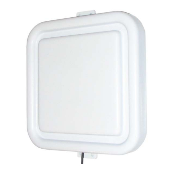
ID ISC.ANT.U170/170 Leistungsmerkmale der Antenne ID ISC.ANT.U170/170 Die zirkular polarisierte Antenne ID ISC.ANT.U170/170 Typ –EU ist eine Antenne, die für die Be- triebsfrequenzen im UHF-Bereich von 865 MHz – 868 MHz geeignet ist. Durch die zirkulare Polarisation ist ein Lesen von Transpondern in zwei Ausrichtungen möglich. -
Seite 7: Montage
® OBID i-scan Montage ID ISC.ANT.U170/170 Montage Die Antenne ist für die Montage auf Wänden oder an Halterungen innerhalb von Gebäuden konzi- piert. Zur Montage dürfen nur die am Gehäuse vorgesehenen Löcher benutzt werden. Eine spe- zielle Halterung zur Montage an Masten oder Stangen kann bei der Firma FEIG ELECTRONIC GmbH bestellt werden. -
Seite 8: Montage Der Antenne Mit Halterung (Mounting Set)
Masten oder Stangen möglich. Mit dieser Halterung ist die Antenne in drei Richtungen ver- änderbar. Abbildung 2: Montage der Halterung an der Antenne Bezeichnung Bestell-Nummer ID ISC.ANT.U170/170-MS Mounting Set Antenna UHF 3310.000.00.00 FEIG ELECTRONIC GmbH Seite 8 von 24 M81201-1de-ID-B.doc... -
Seite 9: Antennenanschluss
® OBID i-scan Montage ID ISC.ANT.U170/170 3.2 Antennenanschluss Zur Verbindung der Antenne mit dem Leser stehen Ihnen 2 fertig konfektionierte Antennenkabel zur Verfügung. Diese können in den Längen 2m und 6m bei der Firma FEIG ELECTRONIC GmbH bezogen werden. Länge... -
Seite 10: Vswr
® OBID i-scan Montage ID ISC.ANT.U170/170 VSWR Abbildung 3: Typisches VSWR der Antenne ID ISC.ANT.U170/170-EU FEIG ELECTRONIC GmbH Seite 10 von 24 M81201-1de-ID-B.doc... -
Seite 11: Antennendiagramme
® OBID i-scan Montage ID ISC.ANT.U170/170 Antennendiagramme Abbildung 4: Typisches Antennendiagramm der Antenne ID ISC.ANT.U170/170-EU horizontal Abbildung 5: Typisches Antennendiagramm der Antenne ID ISC.ANT.U170/170-EU vertikal FEIG ELECTRONIC GmbH Seite 11 von 24 M81201-1de-ID-B.doc... -
Seite 12: Technische Daten
® OBID i-scan Montage ID ISC.ANT.U170/170 Technische Daten Mechanische Daten • Kunststoff ASA/ABS Gehäuse • Abmessungen ( B x H x T ) 170 x 170 x 25 mm±2 mm • Gewicht ca. 270 g • Farbe Weiß • Schutzart... - Seite 13 ® OBID i-scan Montage ID ISC.ANT.U170/170 Mechanische Daten Halterung (Mounting Set) • Material Edelstahl, Stahl verzinkt • Klemmbereich – für Rundprofile ca. 30 mm - 60 mm • ca. 480 g Gewicht • Ausrichtung der Antenne In 3 Achsen veränderbar...
- Seite 14 ® OBID i-scan Installation ID ISC.ANT.U170/170 Note © Copyright 2008/2009 by FEIG ELECTRONIC GmbH Lange Strasse 4 D-35781 Weilburg Tel.: +49 6471 3109-0 http://www.feig.de With the edition of this document, all previous editions become void. Indications made in this manual may be changed without previous notice.
- Seite 15 ® OBID i-scan Installation ID ISC.ANT.U170/170 Contents Safety Instructions / Warning - Read before start-up ! Performance Features of the antenna ID ISC.ANT.U170/170 Installation Installation with Mounting Set..................19 Antenna cable ......................20 VSWR Antenna pattern Technical Data FEIG ELECTRONIC GmbH Page 15 of 24...
-
Seite 16: Safety Instructions / Warning - Read Before Start-Up
® OBID i-scan Installation ID ISC.ANT.U170/170 Safety Instructions / Warning - Read before start-up ! • The device may only be used for the intended purpose designed by for the manufacturer. • The operation manual should be conveniently kept available at all times for each user. -
Seite 17: Performance Features Of The Antenna Id Isc.ant.u170/170
ID ISC.ANT.U170/170 Performance Features of the antenna ID ISC.ANT.U170/170 The antenna ID ISC.ANT.U170/170 Type –EU is a circular polarized antenna and can be used at operating frequencies in the UHF range from 865 MHz – 868 MHz. Due to the circular polarization a reading of Transponder in two orientations is possible. -
Seite 18: Installation
® OBID i-scan Installation ID ISC.ANT.U170/170 Installation The antenna is designed for wall or fixture mounting. Mounting holes are provided in the housing. Please note that only these holes should be used when mounting the antenna. An optional mounting set is available to simplify the attachment of the antenna to portal structures or poles and can be ordered from FEIG ELECTRONIC GmbH. -
Seite 19: Installation With Mounting Set
A special mounting set provides an easy method of mounting of the antenna at a portal, mast, pole or bar. After mounting, the antenna can be changed and positioned at three orientations. Figure 7: Mounting Set with antenna Description Order number ID ISC.ANT.U170/170-MS Mounting Set Antenna UHF 3310.000.00.00 FEIG ELECTRONIC GmbH Page 19 of 24 M81201-1de-ID-B.doc... -
Seite 20: Antenna Cable
® OBID i-scan Installation ID ISC.ANT.U170/170 3.2 Antenna cable There are two antenna cable assemblies available for the extension of the antenna cable. These cable assembly can be ordered by FEIG ELECTRONIC GmbH in a two meter (2 m) or six meter (6 m) version. -
Seite 21: Vswr
® OBID i-scan Installation ID ISC.ANT.U170/170 VSWR Figure 8: Typical VSWR of the antenna ID ISC.ANT.U170/170-EU FEIG ELECTRONIC GmbH Page 21 of 24 M81201-1de-ID-B.doc... -
Seite 22: Antenna Pattern
® OBID i-scan Installation ID ISC.ANT.U170/170 Antenna pattern Figure 9: Typical antenna pattern of the Antenna ID ISC.ANT.U170/170-EU horizontal Figure 10: Typical antenna pattern of the Antenna ID ISC.ANT.U170/170-EU vertical FEIG ELECTRONIC GmbH Page 22 of 24 M81201-1de-ID-B.doc... -
Seite 23: Technical Data
® OBID i-scan Installation ID ISC.ANT.U170/170 Technical Data Mechanical Data • Housing plastic ASA-ABS • Dimensions ( W x H x D ) 170 x 170 x 25 mm±2 mm • Weight approx. 270 g • Color white • Protection class... - Seite 24 ® OBID i-scan Installation ID ISC.ANT.U170/170 Mechanical Data Mounting Set • Material stainless steel, steel zinc-plate • clamping zone - circular profile 30 mm - 60 mm • Weight approx. 480 g • alignment of the antenna Adjustable at three orientation...